MaTouch ESP32-S3 7” Parallel TFT with Touch
1. Introduction
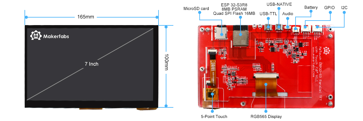
The 7-inch screen uses the esp32-s3 chip as the controller and also includes the audio function. The TF card solves the problem of audio and picture storage, and it also has an expandable io port, and there is also a 16G SD card in the display, so customers do not need to bother purchasing the SD cards. Therefore, such a product is very suitable as a Screen display solution for IoT. At the same time, we have configured two different resolution versions for selection to meet the screen display requirements under different needs.
Model:MTESPS37
2. Features
- ESP32-S3-WROOM Controller
- Working voltage 4.75-5.25V
- Resolution: 800x480(HD), 1024x600(UHD)
- FPS: >15
- LCD interface: RGB 565
- Touch Panel Driver: GT911
- Touch Panel: 5 Points Touch, Capacitive
- USB: Dual USB Type-C(one for USB-to-UART and one for native USB)
- Mabee interface: 1I2C;1GPIO
- Button: Flash button and reset button
- MicroSD: Yes
- Onboard SD card socket
- Type-C Power Delivery: Not Supported
- Extended IO for applications' usage
- I2S Audio output (MAX98357A/MAX98357B)
- Screen outline:164.90x100.00 mm
- Operation temperature: -40℃ to +85℃
- Working current: > 600mA
3. Usage in Arduino IED
Due to the 7" screen working current needs to be greater than 600mA, if users found that the screen continues to restart after the program upload is finished, it may be the current is not enough to drive the board. Please check whether the input current meets the requirements.
3.1 Software setup
To ensure the running environment, the same version is recommended.
Note: When users use the MaTouch ESP32-S3 Parallel 7-inch TFT with Touch, It has two versions with different resolutions, and the demos used need to modify the corresponding macro definition to run well,please attention to the version of the resolution.
#define SCREEN_HD    //1024*600
// #define SCREEN_NORMAL     //800*480
All the projects are based on ESP32-S3 development board. If you didn't install the ESP32 Board SDK, you can follow this guide to learn how to do it.
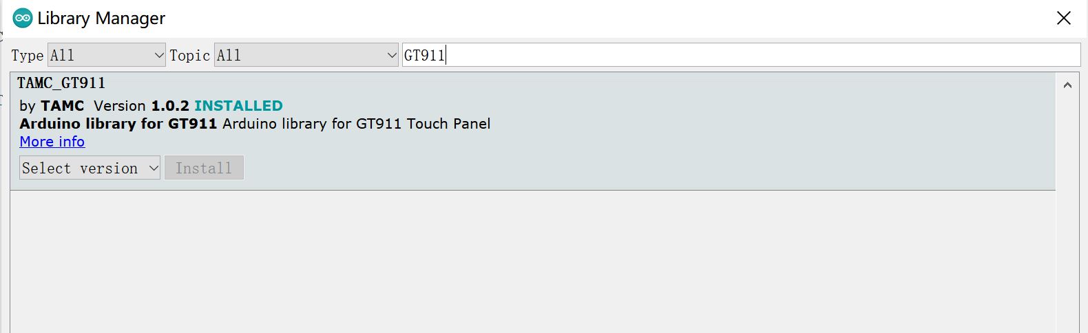
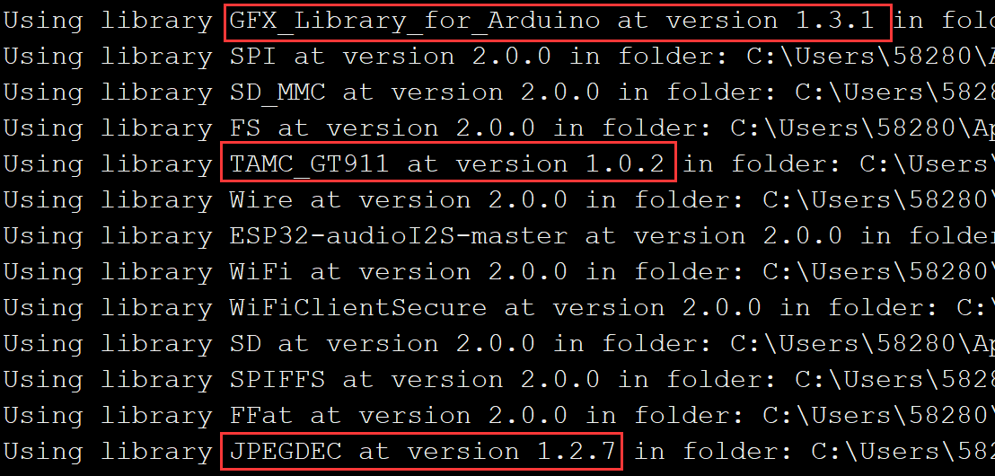
1.Installed the "TAMC_GT911" in the Arduino IDE.
- Click “Tools --> Manager Libraries” to search for and install the 1.0.2 version of TAMC_GT911 library.
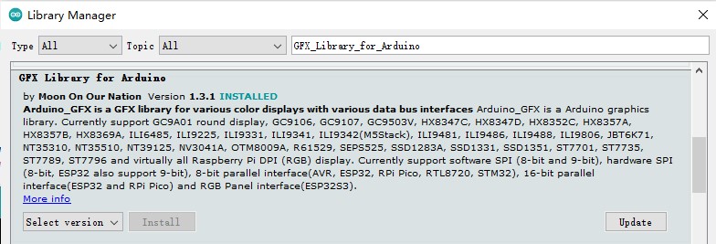
2.Installed the "GFX_Library_for_Arduino" v1.3.1 in the Arduino IDE.
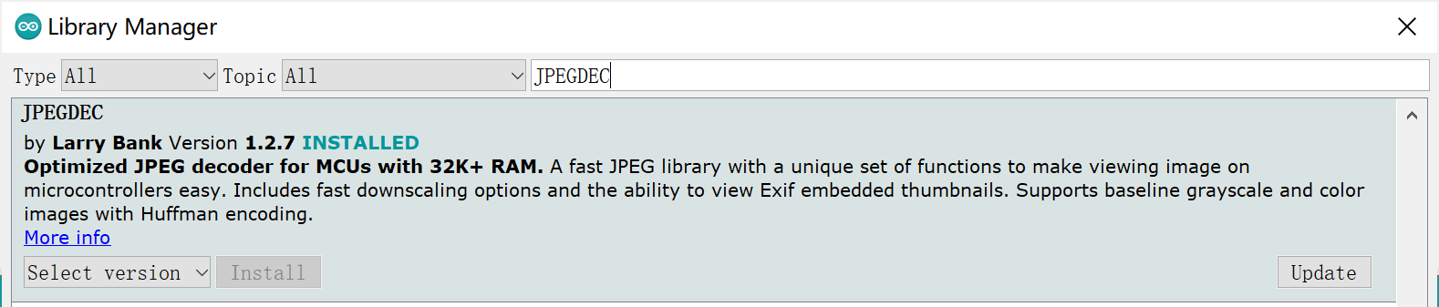
3.Installed the "JPEGDEC" v1.2.7 in the Arduino IDE.
4.Installed the ESP32audioI2S.zip in the Arduino IDE.
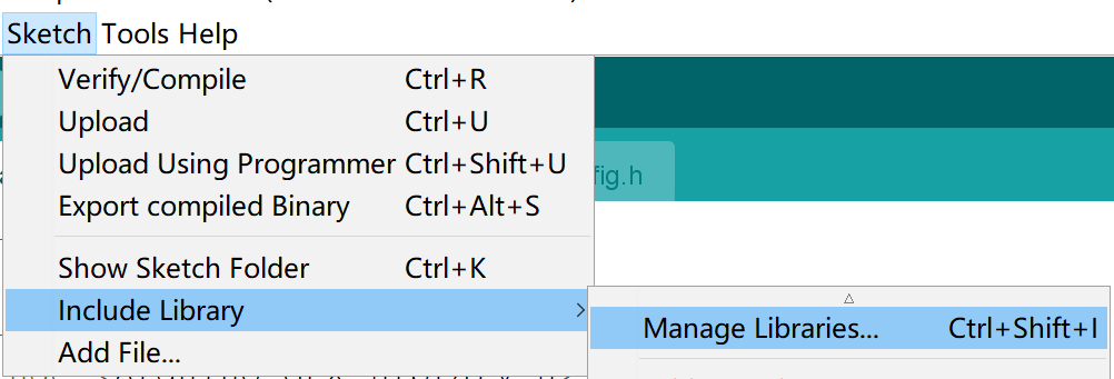
- Click "Code --> Download ZIP", wait for the download to complete.
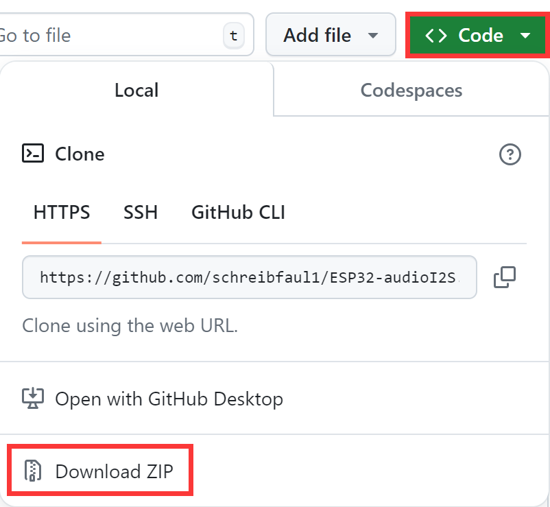
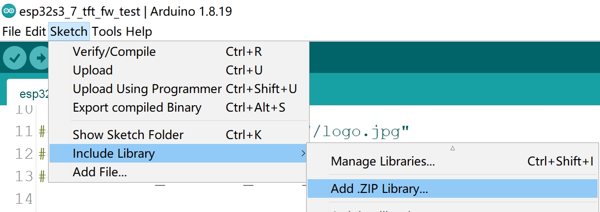
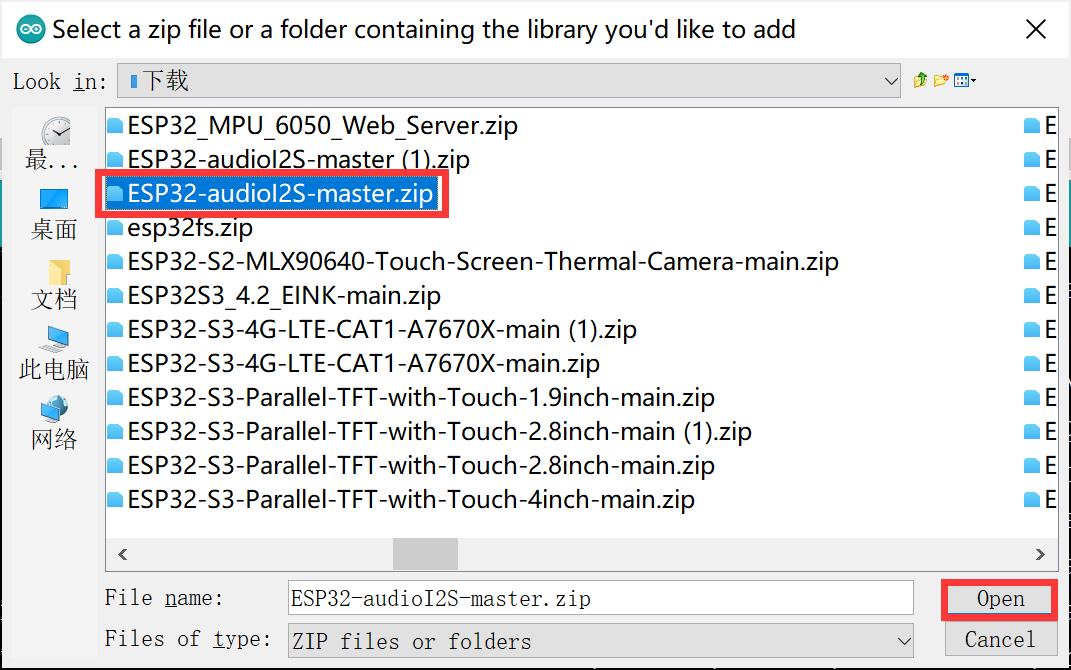
- Click "Sketch --> Include Library --> ADD ZIP Library", add the zip you download and click "Open".
Before uploading the sketch, select and set the parameter in the Tools menu, as picture:
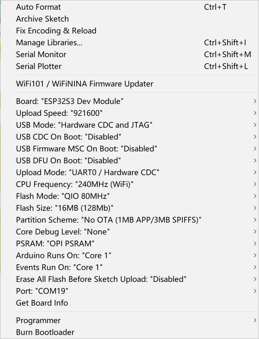
Note: Different computers may have different port numbers when connecting to a development board. Please select the correct port number based on the development board you are connecting to.
If you need compile some project with UI, please choose the "ESP32-S3 Dev module", flash size is 16MB, PSRAM is OPI PSRAM, Partition Scheme is 16M Flash (3MB APP/9.9MB FATFS), Erase ALL Flash Before Sketch Upload is Enabled, and choose the com. verify and upload the code.
If you still think the flash is too small, you can refer to this wiki for larger flash and memory options for ESP32S3 in Arduino IDE.
3.2 FW_Test Demo
This is the factory firmware program, used to check whether the screen works normally.
-
Get the code esp32s3_7_tft_fw_test
-
Open the esp32s3_7_tft_fw_test.ino, check whether the macro definitions in the file correspond.
-
You can check if the version of the download library is correct.
-
Unzip the sd_1024.zip / sd_800.zip and you will get some images and an MP3 file, the files need to be downloaded into the SD card, and the SD card will be used in the demo.
-
Plug the SD card into the SD card slot.
-
Choose the “ESP32-S3 Dev module”, and choose the com.
-
Verify and upload the sketch.
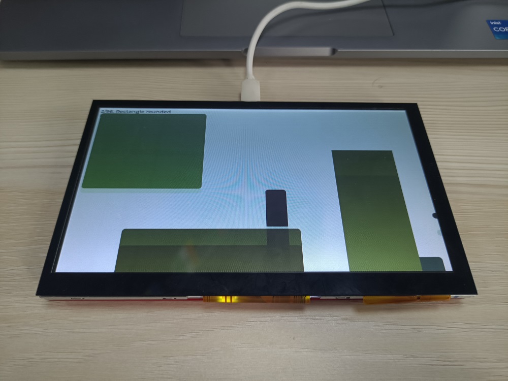
3.3 LvglBenchmark Demo
The lvglbenchmark demo tests the performance in various cases. For example rectangle, border, shadow, text, image blending, image transformation, blending modes, etc.
- Get the code in lvglBenchmark demo
- Open the LvglBenchmark.ino, check whether the macro definitions in the file correspond.
- Verify and upload the sketch.
- When the program is uploaded successfully, the screen will display the demo.
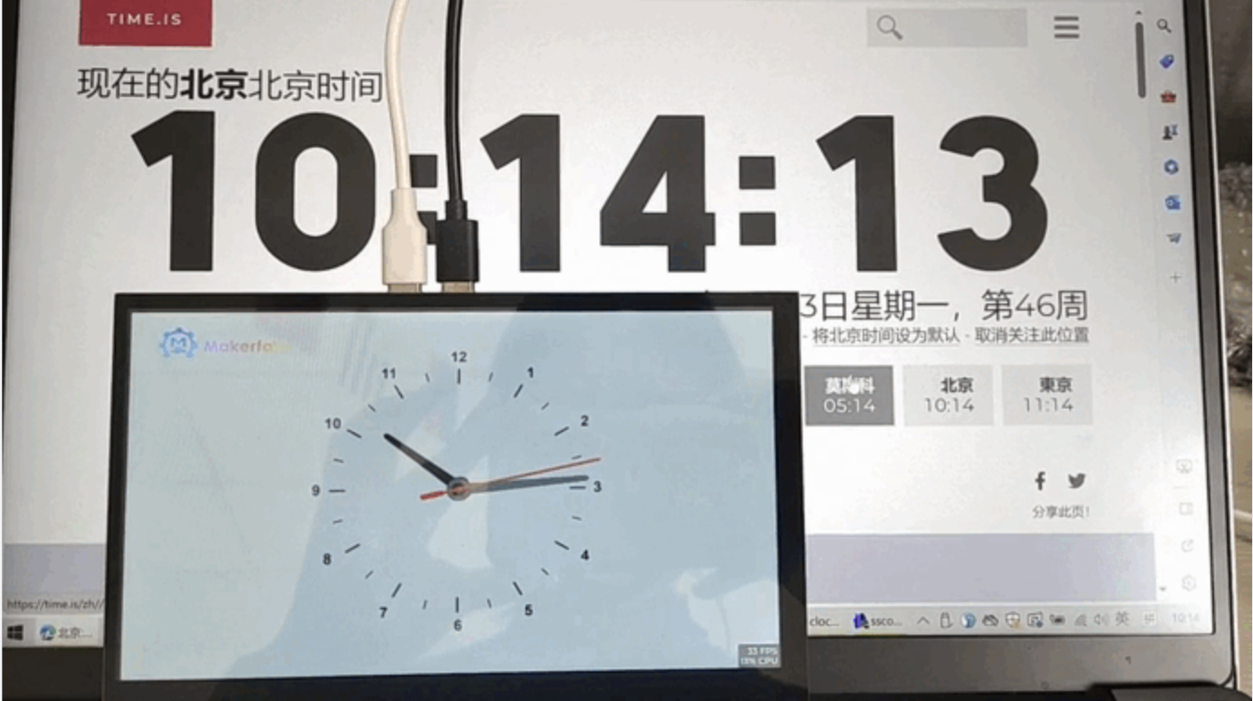
3.4 LvglClock Demo
This project is to display a real-time clock.
- Get the code in LvglClock demo
- Open the clock.ino, check whether the macro definitions in the file correspond.
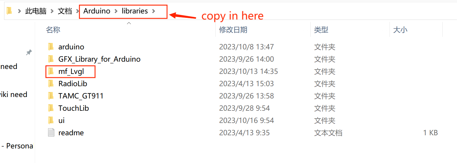
- Install "mf_Lvgl" library
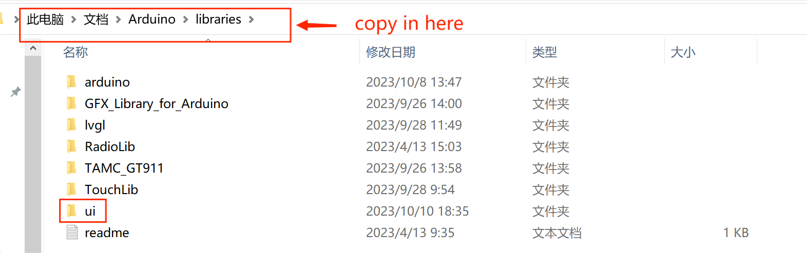
unzip the "mf_Lvgl.zip", and copy it to the library file of Arduino, General Arduino library folder path for: C:/Users/Document/Arduino/libraries.
And it is also OK to open the sketch>include library> ADD.ZIP library,choose the download path of mf_Lvgl to add the library to the Arduino library file.
The lv_conf.h file is included in the library
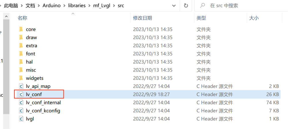
The lvgl_conf.h file is a setup file used to configure the lvgl library. It gets created when Squareline exports the project file. It contains options for turning on/off features, choosing colors, and setting up fonts.
/* clang-format off */
#if 1 /*Set it to "1" to enable content*/

/*Color depth: 1 (1 byte per pixel), 8 (RGB332), 16 (RGB565), 32 (ARGB8888)*/
#define LV_COLOR_DEPTH 16

/*Use a custom tick source that tells the elapsed time in milliseconds.
 *It removes the need to manually update the tick with `lv_tick_inc()`)*/
#define LV_TICK_CUSTOM 1
#if LV_TICK_CUSTOM
    #define LV_TICK_CUSTOM_INCLUDE "Arduino.h"         /*Header for the system time function*/
    #define LV_TICK_CUSTOM_SYS_TIME_EXPR (millis())    /*Expression evaluating to current system time in ms*/
#endif   /*LV_TICK_CUSTOM*/

/*Montserrat fonts with ASCII range and some symbols using bpp = 4
 *https://fonts.google.com/specimen/Montserrat*/
#define LV_FONT_MONTSERRAT_8  1
#define LV_FONT_MONTSERRAT_10 1
#define LV_FONT_MONTSERRAT_12 1
#define LV_FONT_MONTSERRAT_14 1
#define LV_FONT_MONTSERRAT_16 1
#define LV_FONT_MONTSERRAT_18 1
#define LV_FONT_MONTSERRAT_20 1
#define LV_FONT_MONTSERRAT_22 1
#define LV_FONT_MONTSERRAT_24 1
#define LV_FONT_MONTSERRAT_26 1
#define LV_FONT_MONTSERRAT_28 1
#define LV_FONT_MONTSERRAT_30 1
#define LV_FONT_MONTSERRAT_32 1
#define LV_FONT_MONTSERRAT_34 1
#define LV_FONT_MONTSERRAT_36 1
#define LV_FONT_MONTSERRAT_38 1
#define LV_FONT_MONTSERRAT_40 1
#define LV_FONT_MONTSERRAT_42 1
#define LV_FONT_MONTSERRAT_44 1
#define LV_FONT_MONTSERRAT_46 1
#define LV_FONT_MONTSERRAT_48 1
- Unzip the ui.zip in the library to Arduino library directory, it often located in C:\Users\Administrator\Documents\Arduino\libraries:
Note: If there is already an ui library in the library file of Arduino, delete it first and then add the new ui library, when you compile different project with different ui by Arduino, you need to delete the original ui file and add the this project's ui file.
- Verify and upload the sketch.
- When the program is uploaded successfully, the screen will display the demo.
4. Usage in VS Code & PlatformIO
Downloaded and installed PlatformIO IDE for VSCode.
Note: When users use the MaTouch ESP32-S3 Parallel 7-inch TFT with Touch, It has two versions with different resolutions, and the demos used need to modify the corresponding macro definition to run well,please attention to the version of the resolution.
#define SCREEN_HD    //1024*600
// #define SCREEN_NORMAL     //800*480
4.1 FW_Test Demo
This is the factory firmware program, used to check whether the screen works normally.
-
Unzip the sd_1024.zip / sd_800.zip and you will get some images and an MP3 file, the files need to be downloaded into the SD card, and the SD card will be used in the demo.
-
Plug the SD card into the SD card slot.
Download and unzip the Esp32s3_7_tft_fw_test, open this project by VS Code.
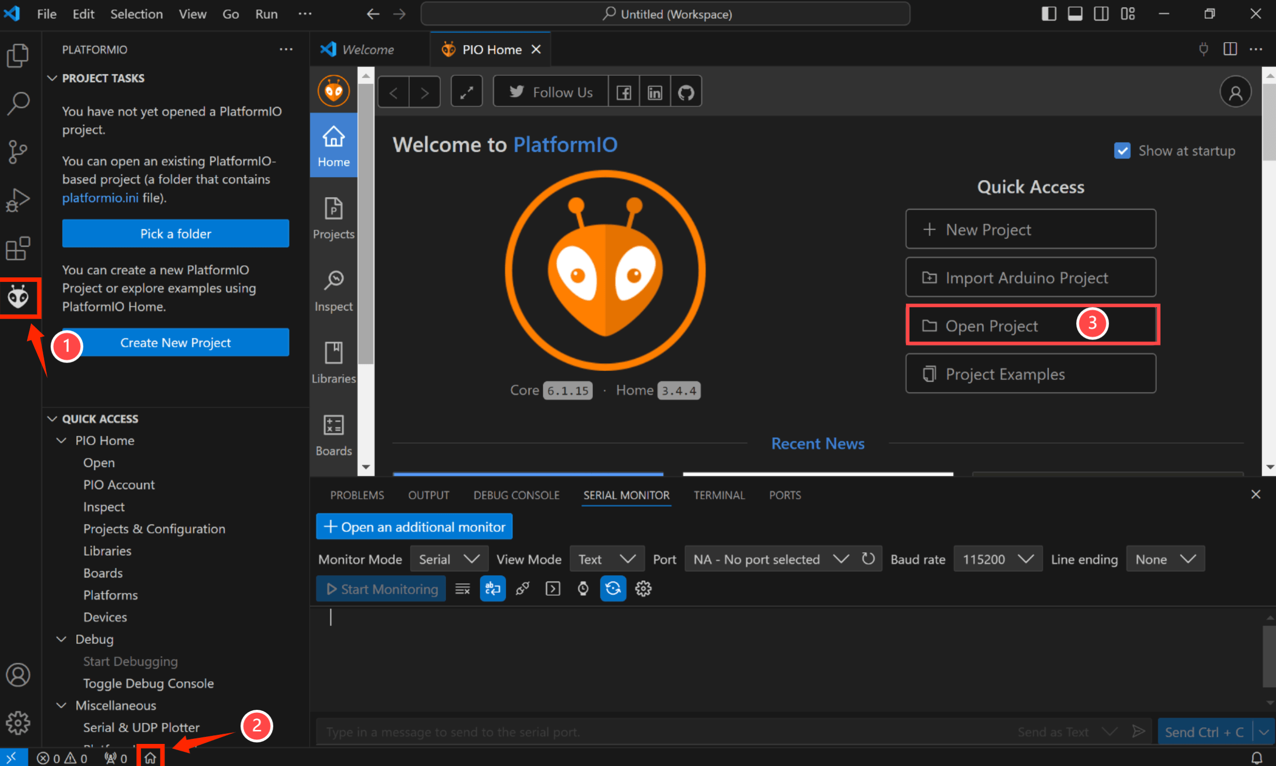
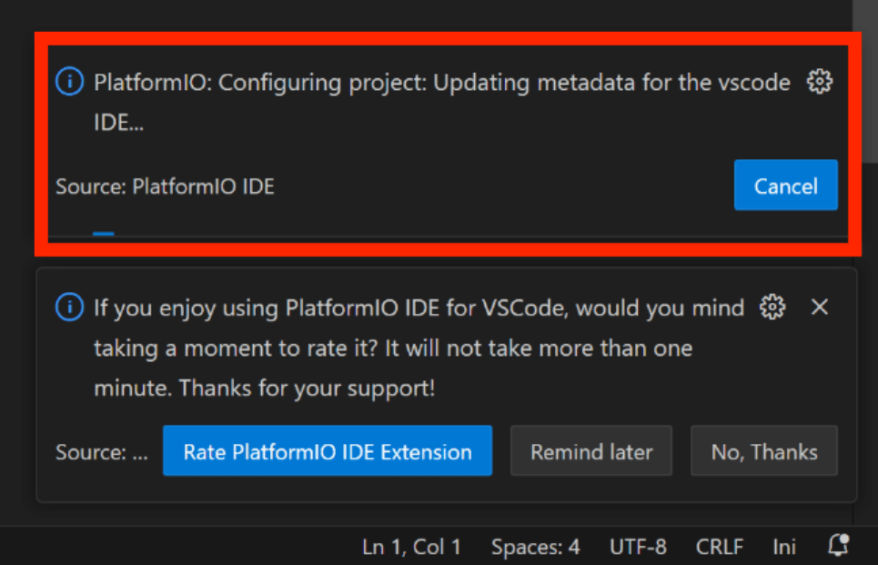
Waiting for configuration project.
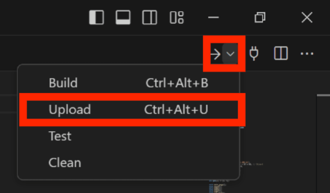
- Click "src-->main.cpp".
Verify it and upload.
4.2 LvglBenchmark Demo
The lvglbenchmark demo tests the performance in various cases. For example rectangle, border, shadow, text, image blending, image transformation, blending modes, etc.
Download and unzip the LvglBenchmark, open this project by VS Code.
Waiting for configuration project.
- Click "src-->main.cpp".
Verify it and upload.
4.3 LvglClock Demo
This project is to display a real-time clock.
Download and unzip the LvglClock, open this project by VS Code.
Waiting for configuration project.
- Click "src-->main.cpp".
Verify it and upload.
5. Usage in SquareLine Studio
If you have not installed SquareLine Studio, please follow this guide to install.
Squareline currently only supports 4", 1.9", 2.1" screens, if you want to use other screens, you need to follow this guide to add the relevant simplified packages.
5.1 LVGL design with SquareLine Studio
1.Click on Squareline to log in to your account, or click on "Sign up" if you don't have one.
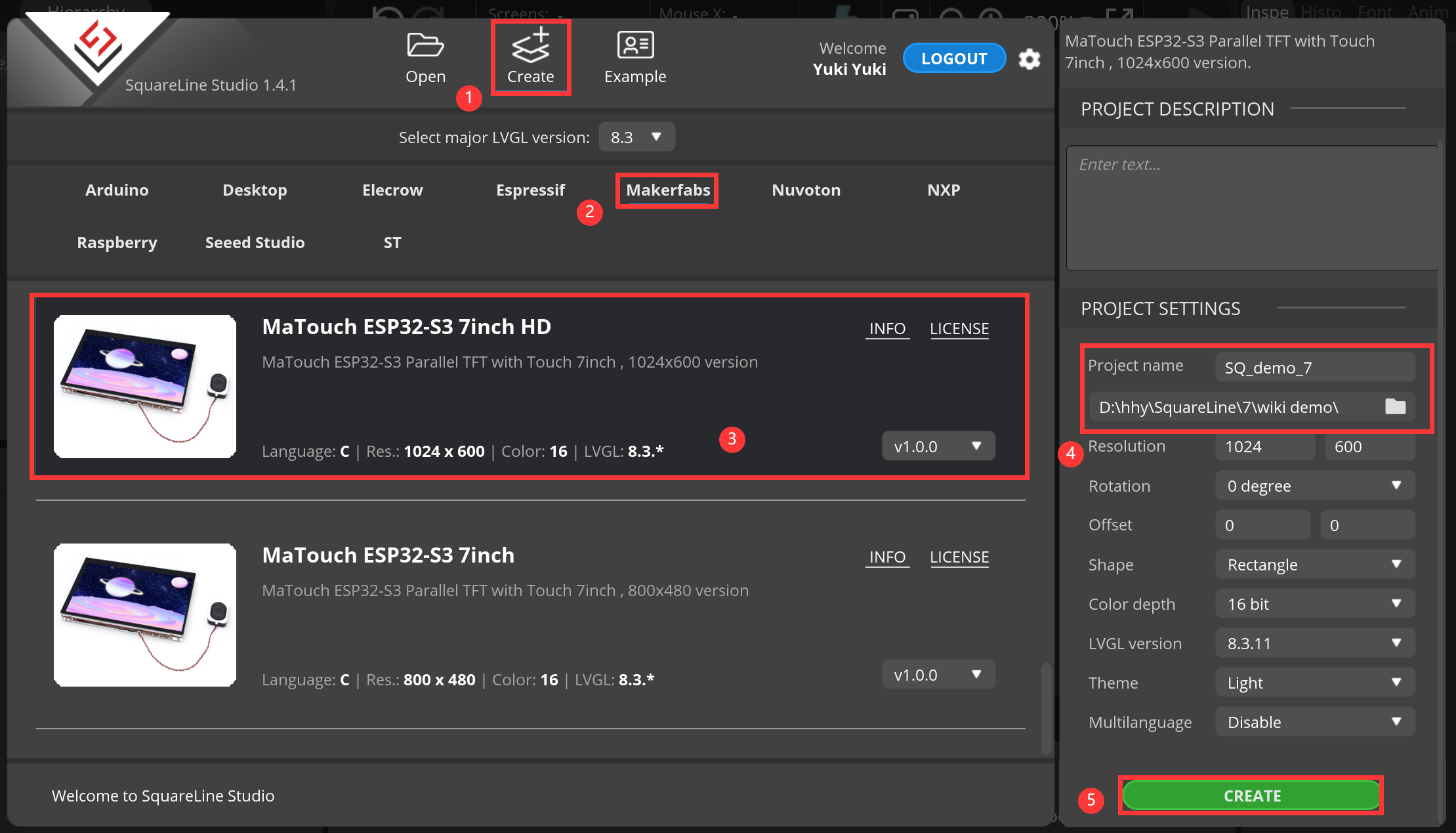
2.Create a project.
-
Click “Crearte-->Makerfabs”.
-
Select “MaTouch ESP32-S3 7inch HD” or “MaTouch ESP32-S3 7inch”
(Note:7inchHD-->1024x600; 7inch-->800x480)
- modify the desired project name and location information.
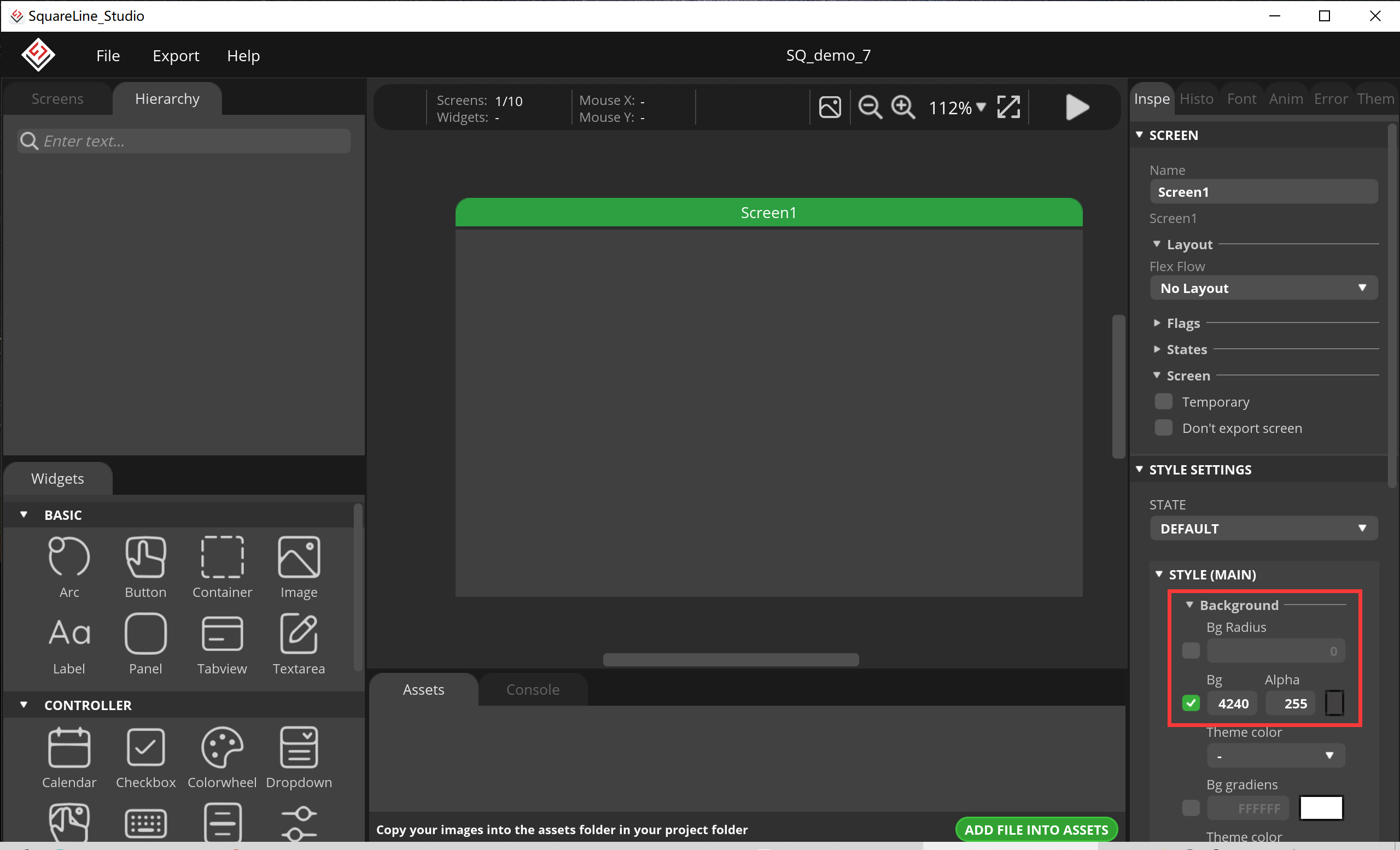
3.Change your favorite background color.
4.Add a Slider.
- Click “Slider”, and set its size, position and value.
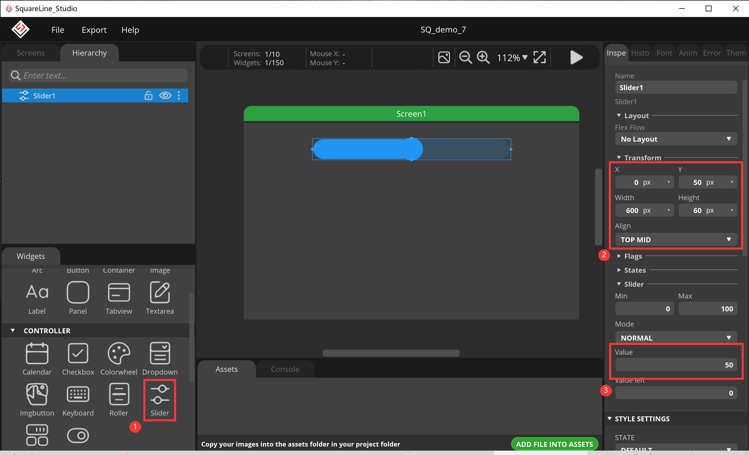
- Set it style.

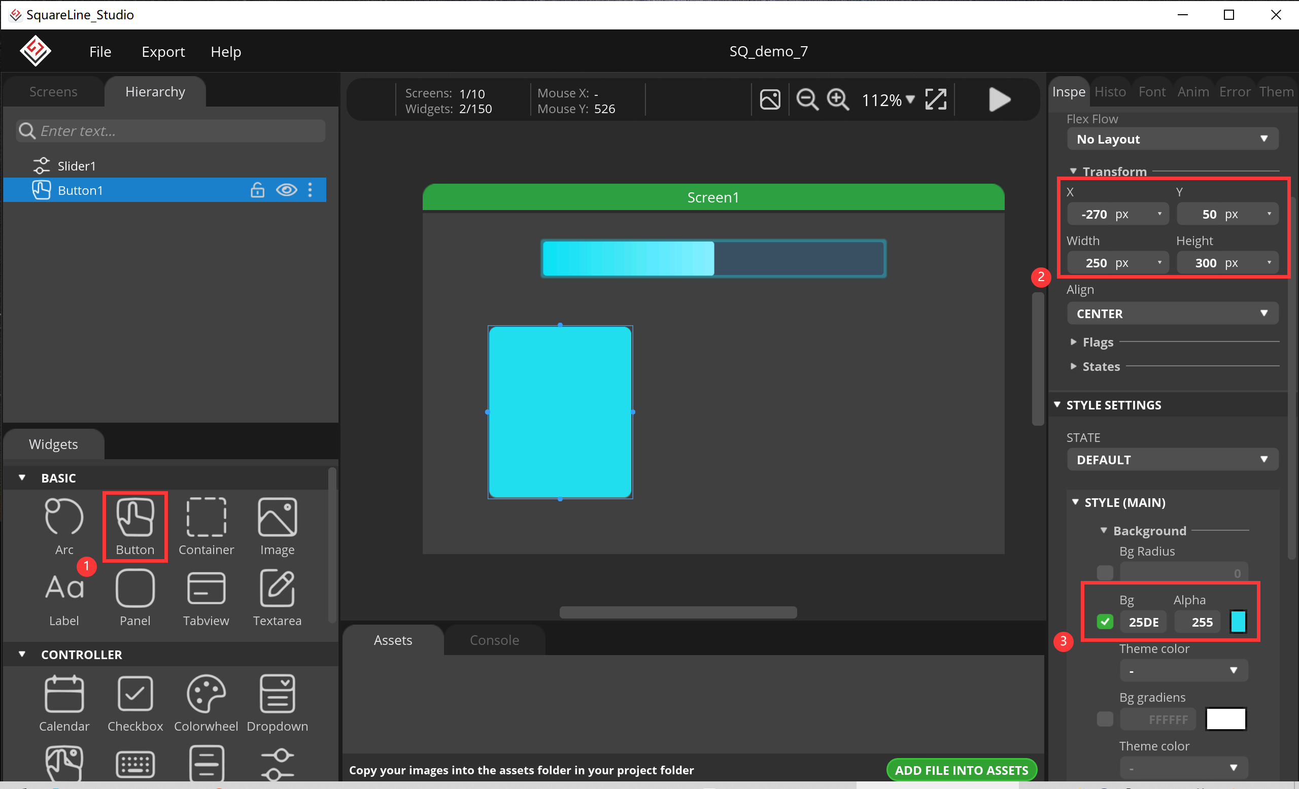
5.Add a button to increase the value of Slider.
- Click “Button”, set its size and position, change its background.
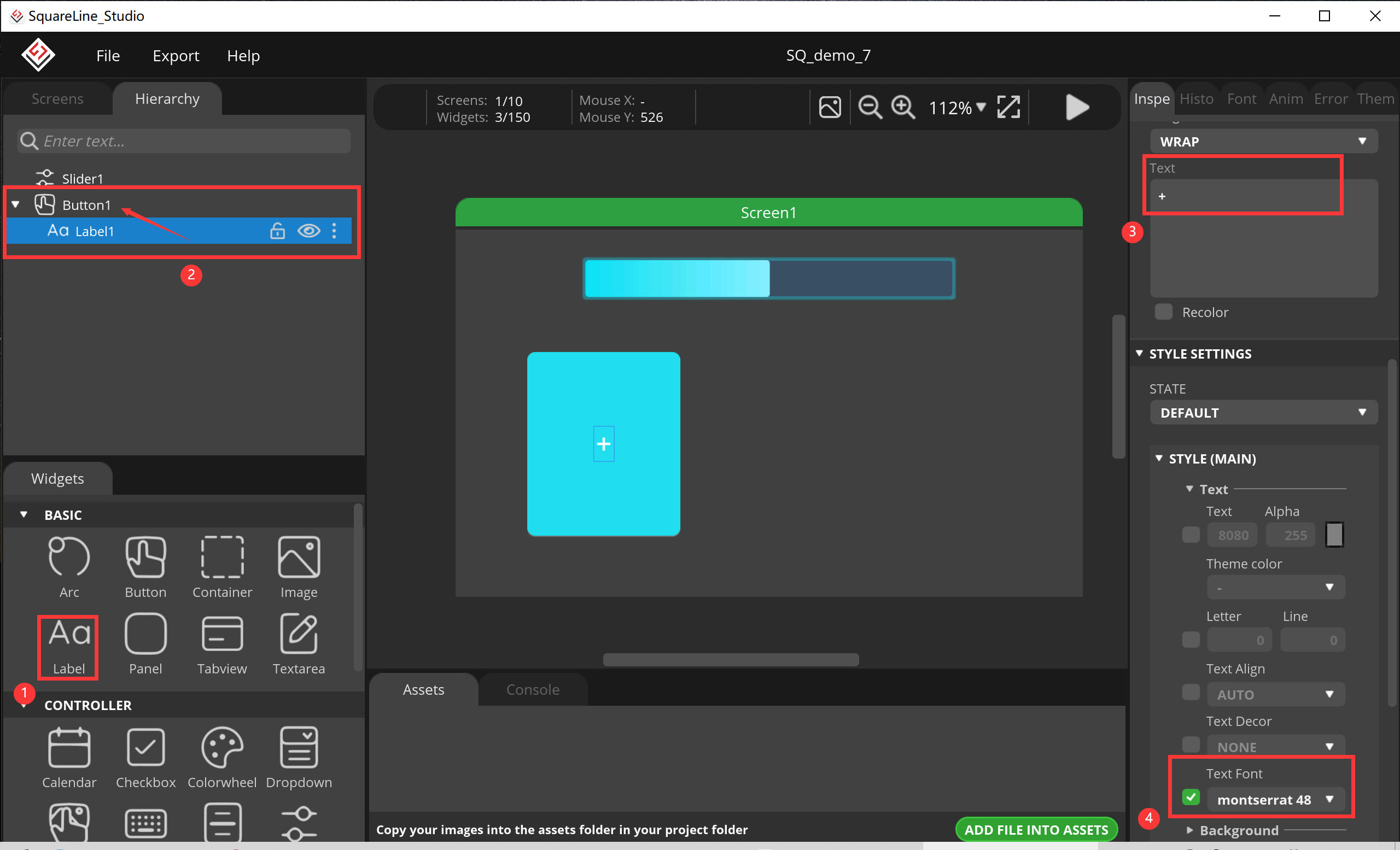
6.Add a Label
-
Pull him into the subclass of button.
-
set its value and size.
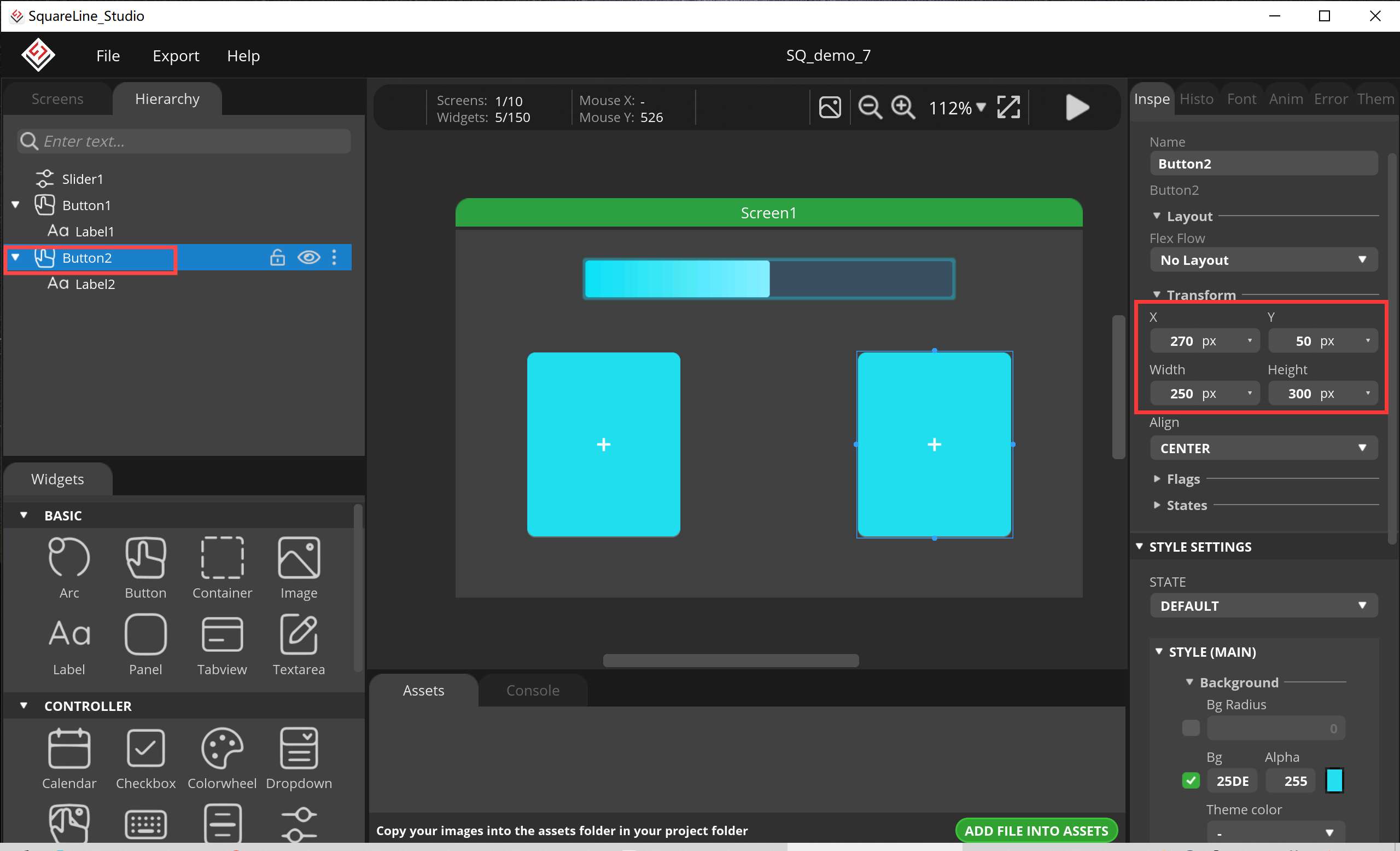
7.In the same way, duplicate a Button.
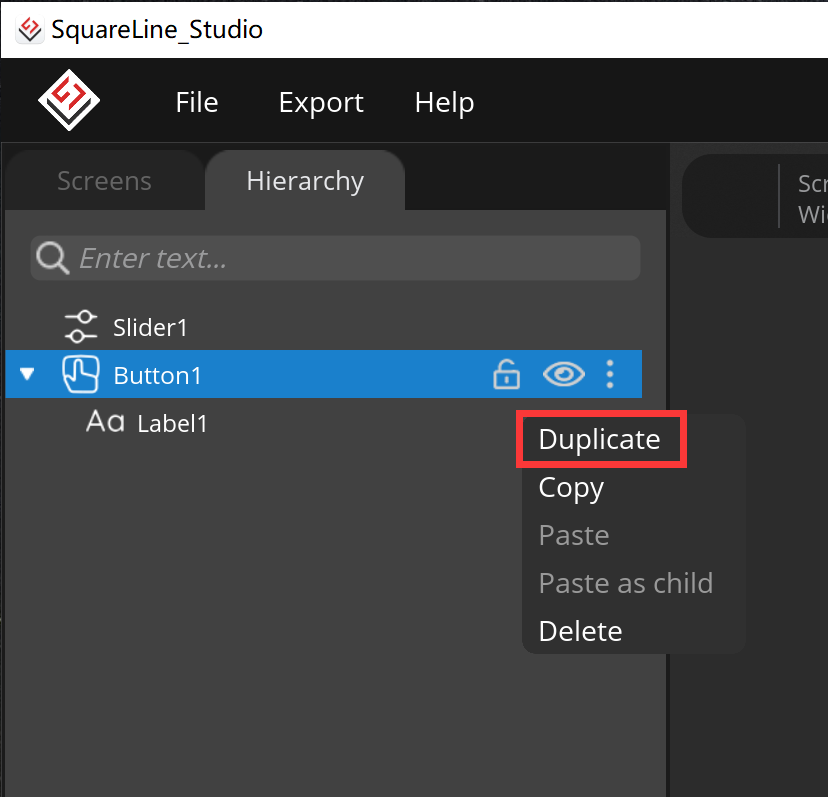
- Set its position.
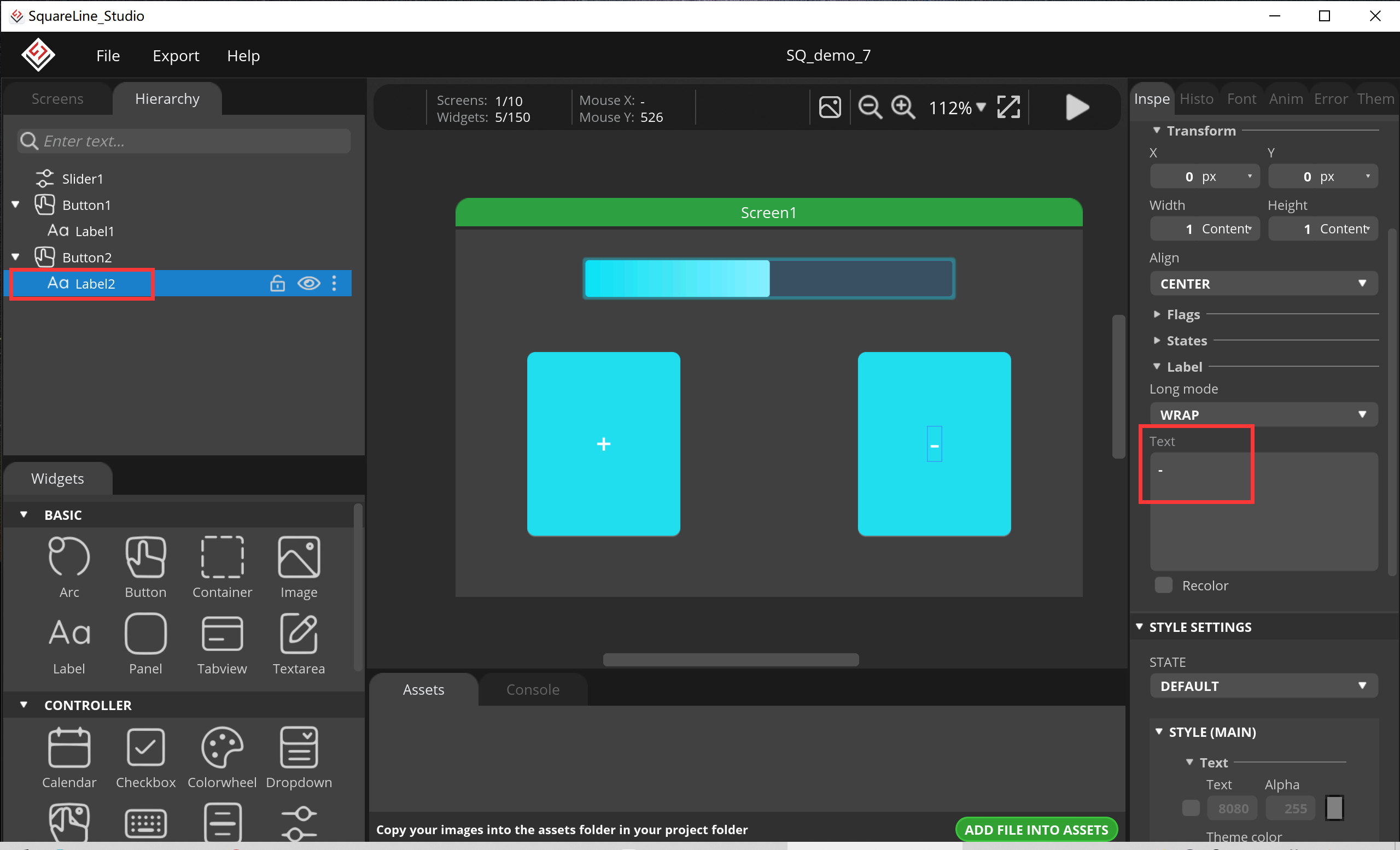
- Change the Label2 value.
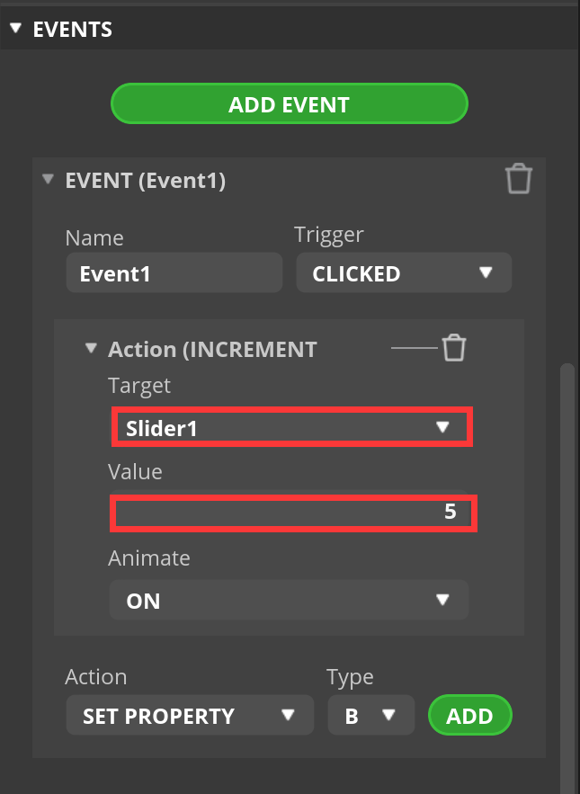
8.Add event, increase the value of Slider when the button is pressed.
- Click “Button1”, select “INCREMENT SLIDER” and click “ADD”.
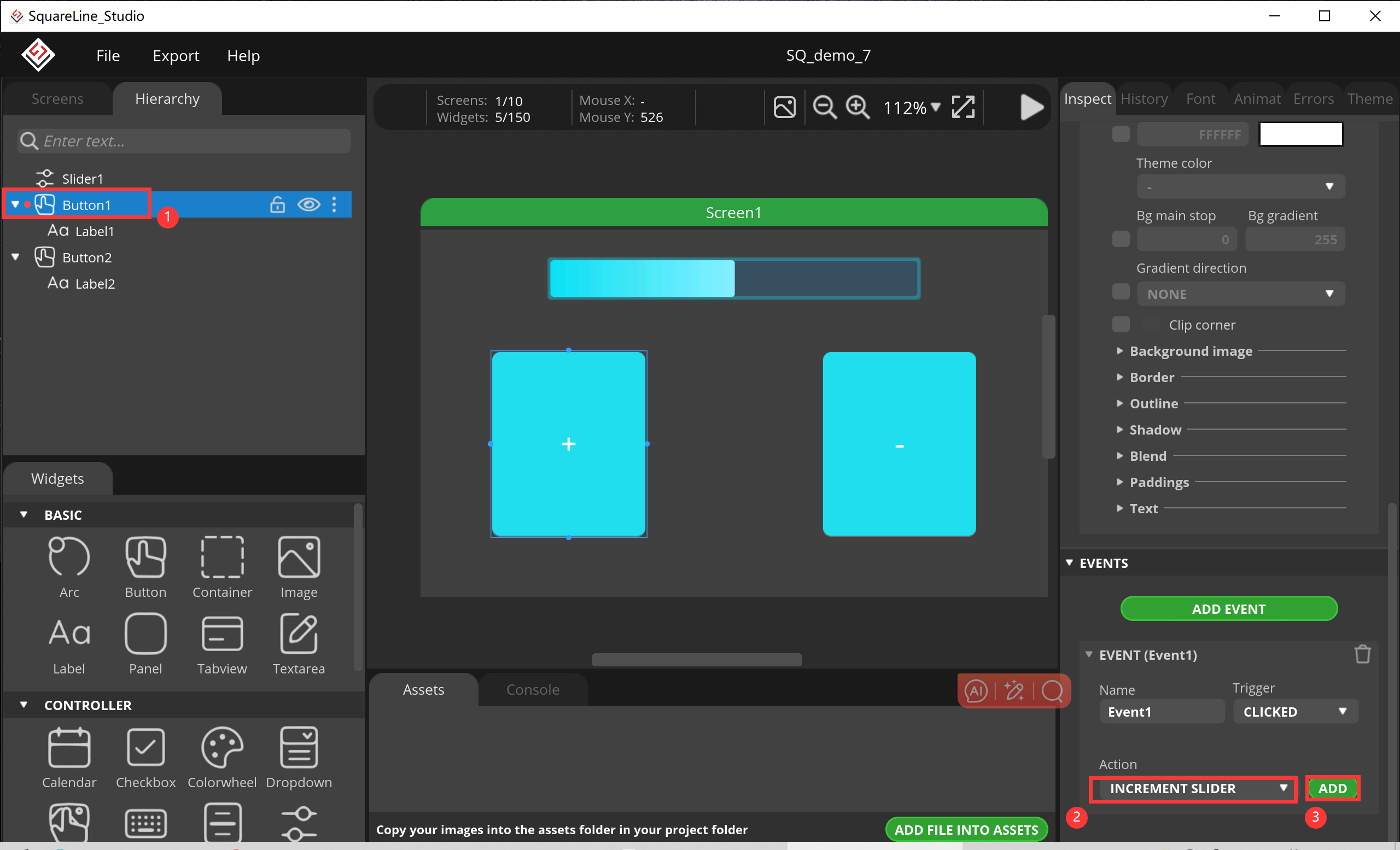
- Select “Slider1”, and set the value to 5.(Pressing once increases the value of Slider by 5)
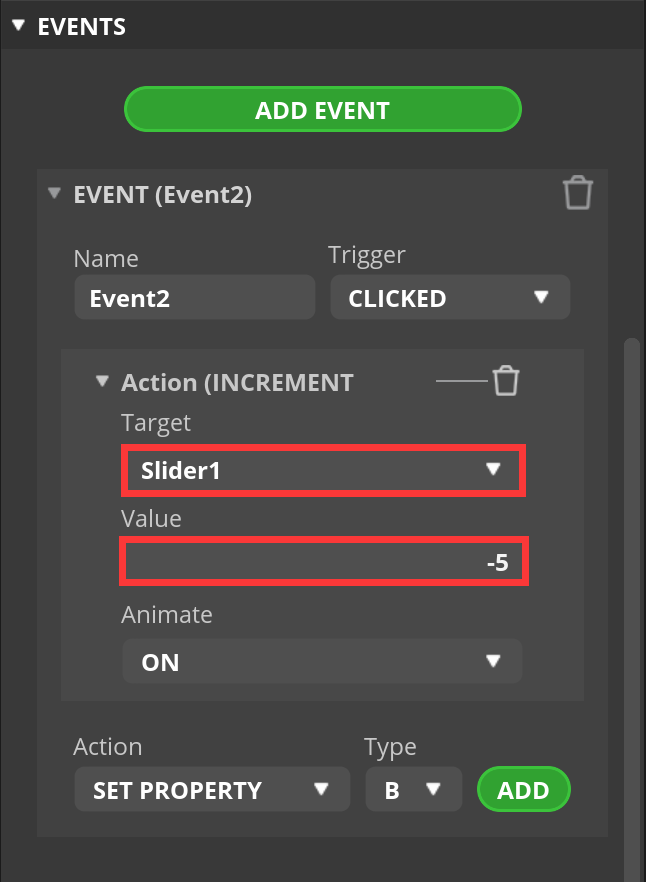
Setting up Button2 in the same way.
-
Click “Button2”, select “INCREMENT SLIDER” and click “ADD”.
-
Select “Slider1”, and set the value to -5.(Pressing once decreases the value of Slider by 5)
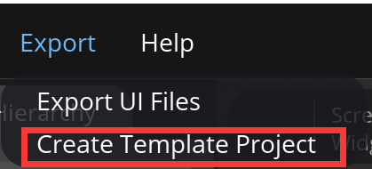
9.Export project.
- Click “Export-->Create Template Project”.
- Export the project file to the location you want.
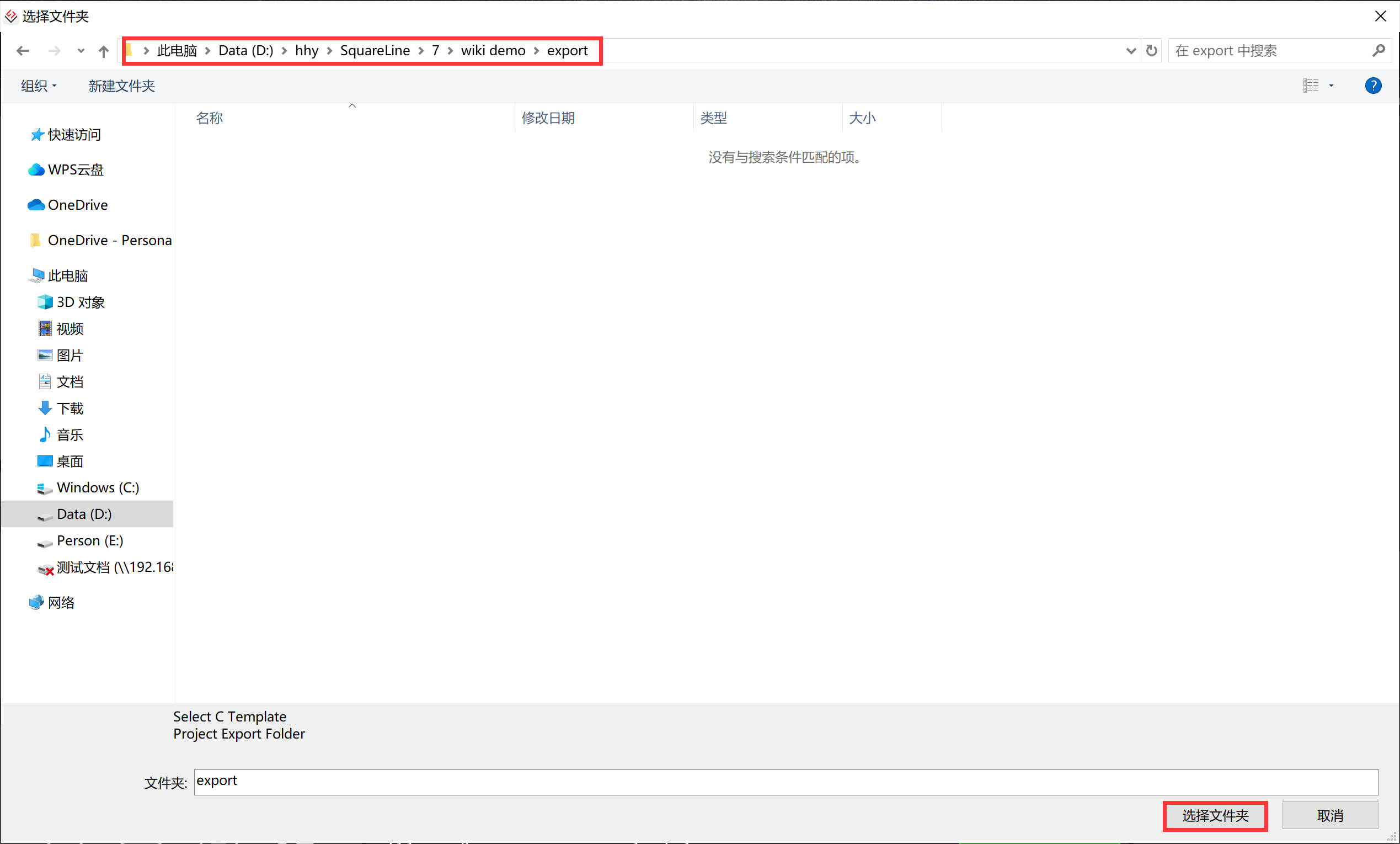
- Wait for export succeed.
5.2 Code Upload with Arduino IDE
This projects are based on ESP32-S3 development board. If you didn't install the ESP32 Board SDK, you can follow this guide to learn how to do it.
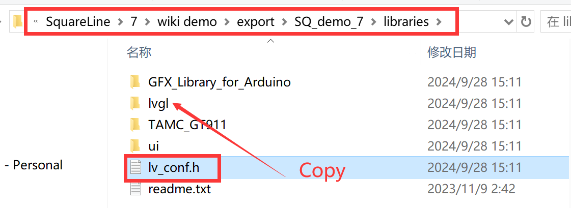
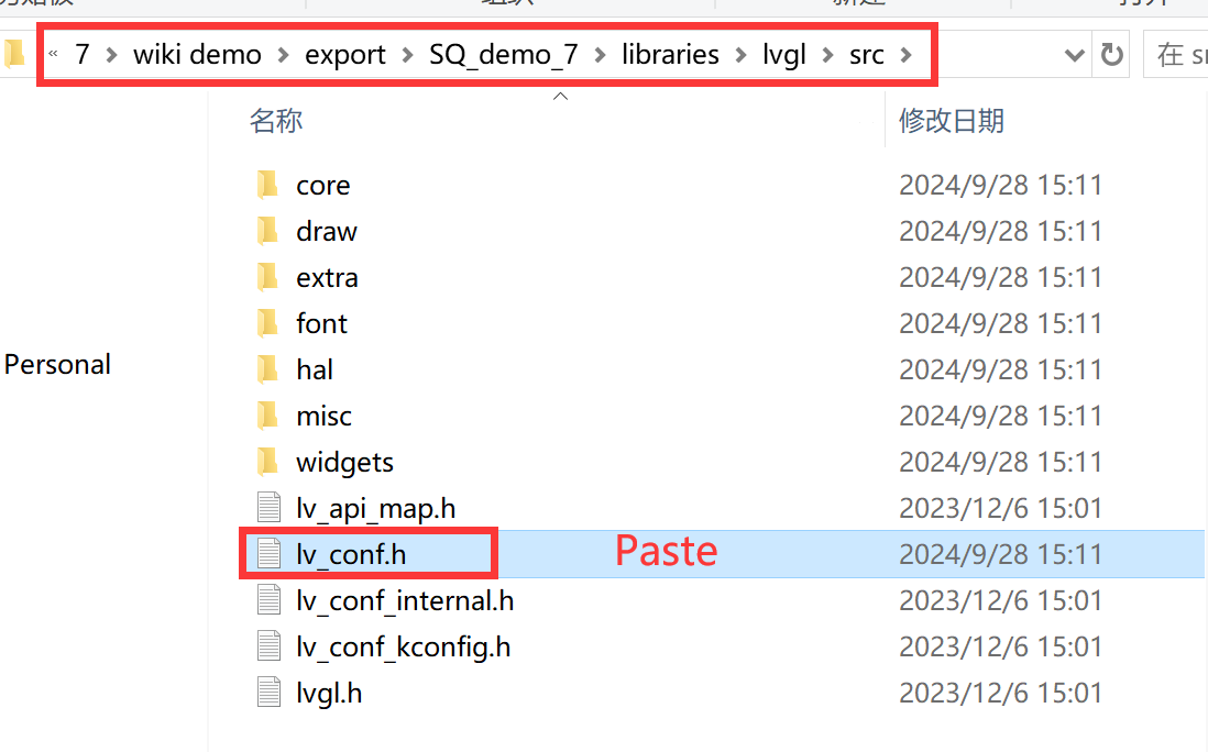
1.Click on the code project document you just export.
- Copy the “lv_conf.h” into the “src” in the lvgl in libraries.
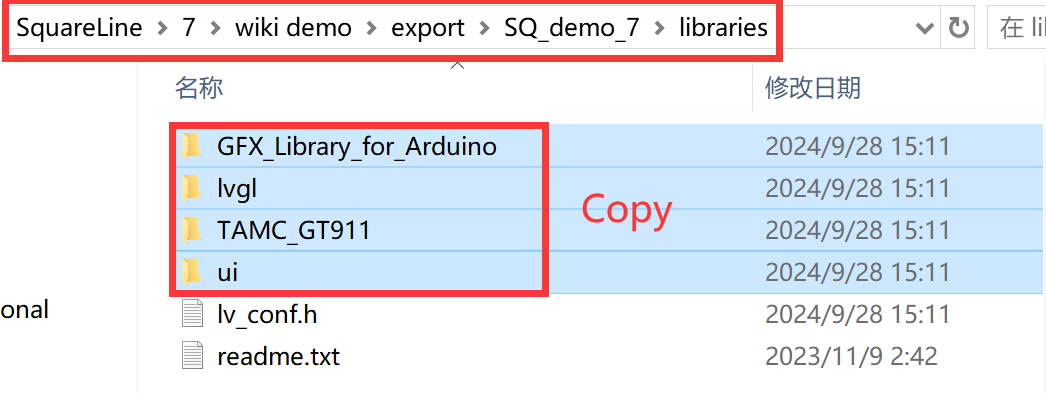
- Copy these files into the Arduino library.
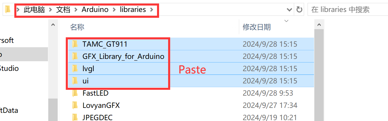
- Open the ui.ino.
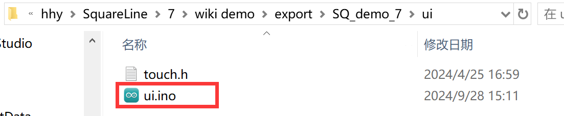
- Before uploading the sketch, select and set the parameter in the Tools menu, as picture:
5.3 Result
6. FAQ
You can list your question here or contact techsupport@makerfabs.com for technology support. Detailed descriptions of your question will be helped to solve your question.
Q1: Why the display fails to respond sometimes I touch?
A1: The touching interface is loose, please reconnect it.
Q2: I get the error "no matching function for call to 'Arduino_ESP32RGBPanel::Arduino_ESP32RGBPanel(int, int, int, int, int, int, int, int, int, int, int, int, int, int, int, int, int, int, int, int, int, int, int)'); ^" when I compile the code, how to solve it?

A2: Mabe you use the newest ArduinoGFX v1.4.9 not the tested v1.3.1. The oringinal code need to make some changes to support v1.4.9 as below:
#if 0  //for Arduino_GFX_Library v1.3.1
Arduino_ESP32RGBPanel *bus = new Arduino_ESP32RGBPanel(
    GFX_NOT_DEFINED /* CS */, GFX_NOT_DEFINED /* SCK */, GFX_NOT_DEFINED /* SDA */,
    40 /* DE */, 41 /* VSYNC */, 39 /* HSYNC */, 42 /* PCLK */,
    45 /* R0 */, 48 /* R1 */, 47 /* R2 */, 21 /* R3 */, 14 /* R4 */,
    5 /* G0 */, 6 /* G1 */, 7 /* G2 */, 15 /* G3 */, 16 /* G4 */, 4 /* G5 */,
    8 /* B0 */, 3 /* B1 */, 46 /* B2 */, 9 /* B3 */, 1 /* B4 */
);

Arduino_RPi_DPI_RGBPanel *gfx = new Arduino_RPi_DPI_RGBPanel(
    bus,
    SCREEN_W /* width */, 1 /* hsync_polarity */, 40 /* hsync_front_porch */, 48 /* hsync_pulse_width */, 128 /* hsync_back_porch */,
    SCREEN_H /* height */, 1 /* vsync_polarity */, 13 /* vsync_front_porch */, 3 /* vsync_pulse_width */, 45 /* vsync_back_porch */,
    1 /* pclk_active_neg */, 16000000 /* prefer_speed */, true /* auto_flush */);
#endif  //end of  for Arduino_GFX_Library v1.3.1

#if 1 //for Arduino_GFX_Library v1.4.7, v1.4.9
Arduino_ESP32RGBPanel *rgbpanel = new Arduino_ESP32RGBPanel(
    40 /* DE */, 41 /* VSYNC */, 39 /* HSYNC */, 42 /* PCLK */,
    45 /* R0 */, 48 /* R1 */, 47 /* R2 */, 21 /* R3 */, 14 /* R4 */,
    5 /* G0 */, 6 /* G1 */, 7 /* G2 */, 15 /* G3 */, 16 /* G4 */, 4 /* G5 */,
    8 /* B0 */, 3 /* B1 */, 46 /* B2 */, 9 /* B3 */, 1 /* B4 */,
    1 /* hsync_polarity */, 40 /* hsync_front_porch */, 48 /* hsync_pulse_width */, 128 /* hsync_back_porch */,
    1 /* vsync_polarity */, 13 /* vsync_front_porch */, 3 /* vsync_pulse_width */, 45 /* vsync_back_porch */);

Arduino_RGB_Display *gfx = new Arduino_RGB_Display(
    SCREEN_W /* width */, SCREEN_H /* height */, rgbpanel, 0 /* rotation */, true /* auto_flush */);
#endif   //End of for Arduino_GFX_Library v1.4.7, v1.4.9