Basic usage of Squareline with MaTouch 2.1
Introduction
In the earlier Squareline wiki titled "Basic usage of Squareline with MaTouch 4.0", it was mentioned that certain display chips may be not compatible with the TFT_eSPI library, and now the MaTouch ESP32 S3 2.1 Rotary TFT with Touch has the same features. So, in the updated "Basic usage of Squareline with MaTouch 2.1" wiki, We also use the GFX_Library_of_Arduino library instead of the driver. This will enable users to use the exported UI examples on the Arduino, and after successfully uploading the code, users will see the Squareline UI displayed on the screen.In this tutorial, you’ll learn how to make a Digital combination lock using SquareLine_Studio.
Basic usage of SquareLine
In the output files of different SquareLine_Studio versions, you might see changes between “ lv_obj_t *xxx ” and “ lv_obj_t * xxx ” in the pointer variable of the “ui_helpers.h” file. Since the Arduino IDE thinks they are two different data types, we suggest using SquareLine_Studio V1.3.0 to make it work better with our lvgl library.
What is SquareLine
SquareLine Studio is a software that allows you to design images on the interface and export them into code which can be added into Arduino IDE to compile.
Create a project
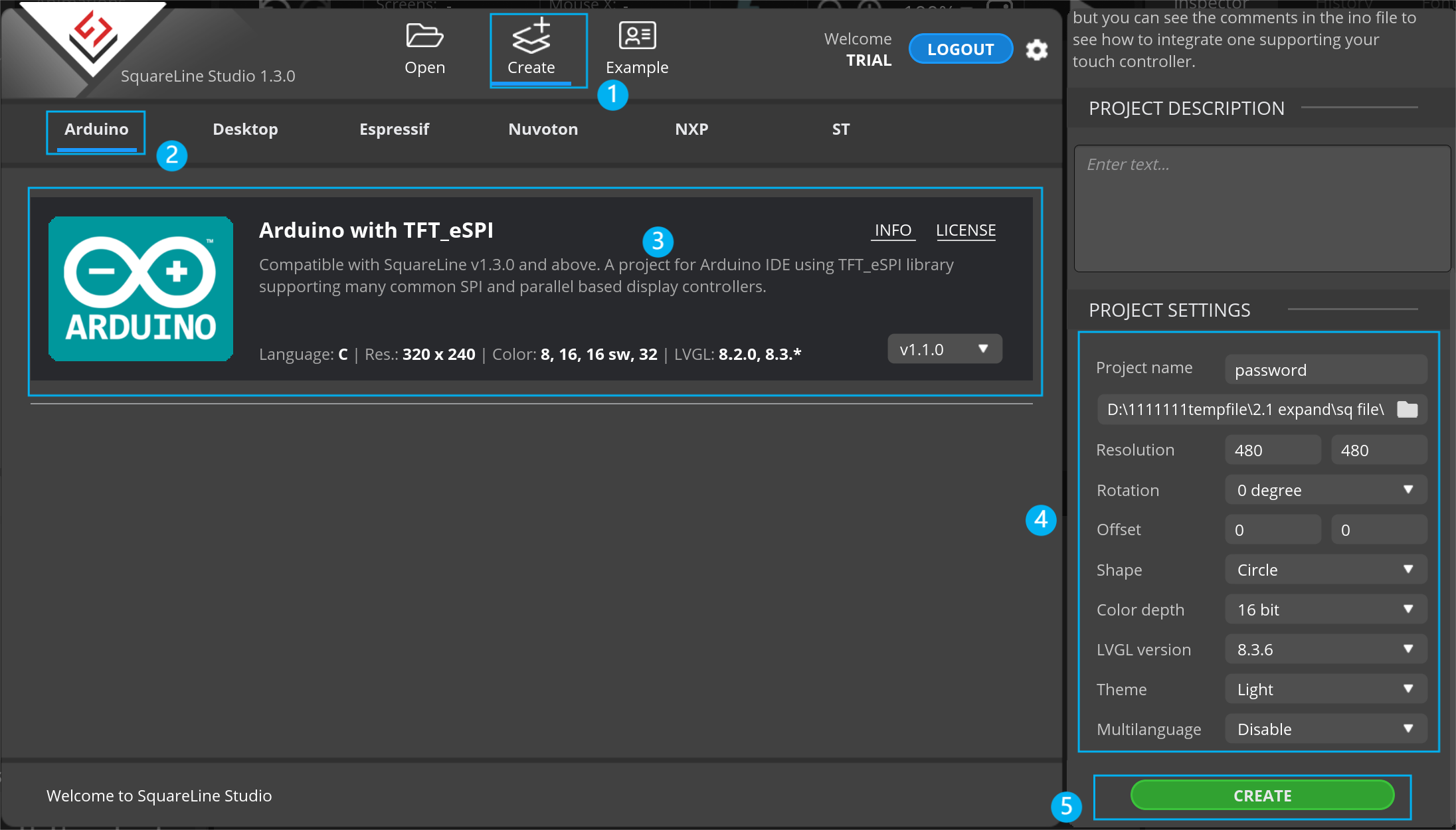
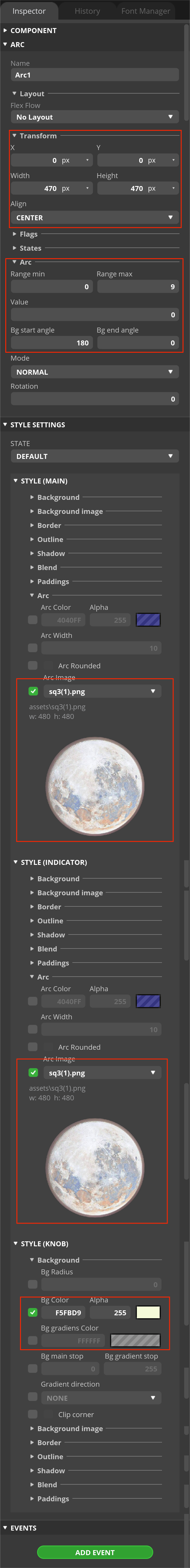
In the Create menu, you can create a new project. Choose a platform to use from the list. Enter the name, the path, and the resolution of your project. Having added all the required parameters, you can create your project. According to the features of MaTouch ESP32 S3 2.1 Rotary TFT with Touch, the resolution is 480*480, the shape is a circle, and the color depth is 16-bit.
Introduction of panels
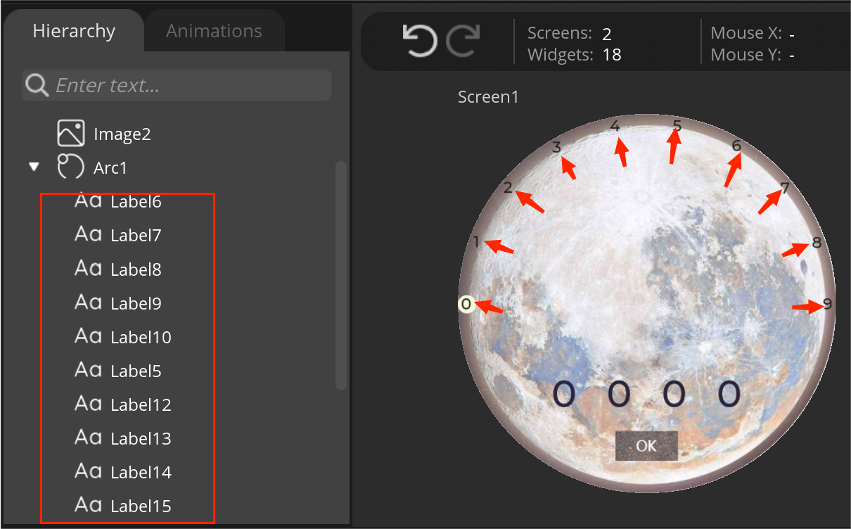
 Hierarchy
In the Hierarchy Panel, you can find the scenes and the list of the widgets appearing on the scenes in hierarchical order. You can modify the widget order, of course.
Animations
You can create and manage custom animations in the Animation Panel. You can add several animation properties to each animation so as to make complex animations.
Widget
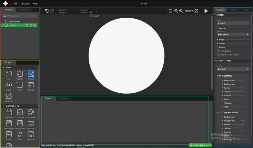
You can find widgets, the basic UI elements, on the Widget Panel. Every widget has its own preference. You can add custom styles to widget components and you are allowed to configure them in different states.
Assets
Images and fonts, added to the project, appear in the Asset Panel. Having created a project, an Asset folder has also been created. If you copy the images needed for your project there, the program will load them automatically listing them in the Asset Panel. Images are allowed in PNG and JPG format. If you double-click on the image in the Asset Panel, it will be opened in the default image browser.
Console
You can find program logos and error messages in the Console Panel.
Inspector
In the Inspector Panel, there are the parameters of the selected widgets. You can add styles and events to them.
History
There is a list of your actions in the History Panel. The program can record up to 200 actions into the list. Selecting any action on the list, the project sets back into that previous state. If you modify any element of your project after setting it back, actions after the selected one disappear.
Font Maker- Create custom fonts.
Use your operation system fonts in your embedded GUI, as well. LVGL applies UTF-8 encoding to display Unicode characters in any language. Here, you can generate a new font for your GUI project. With the font converter tool, you can create C array from any TTF or WOFF font. You can select ranges of Unicode characters and specify the bpp (bit-per-pixel).
Simple UI design
Now, using SquareLine_studio, you can begin your UI design.
First, add the images and fonts you like to assets, and then it allows you to select them and widget components to design the scenes.
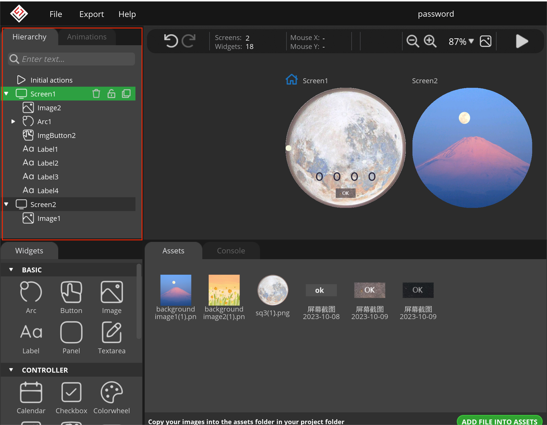
Create 10 labels and place them in the positions corresponding to arc_value from 0 to 9
After, clicking the widget of the list on the Hierarchy panel, you can modify the parameters of the select widget on the Inspector panel, all is determined by your preference.
-
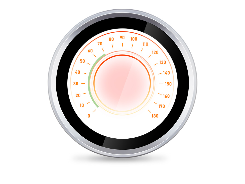
Click Arc1 and modify the parameter as shown in parameter of Arc1
-
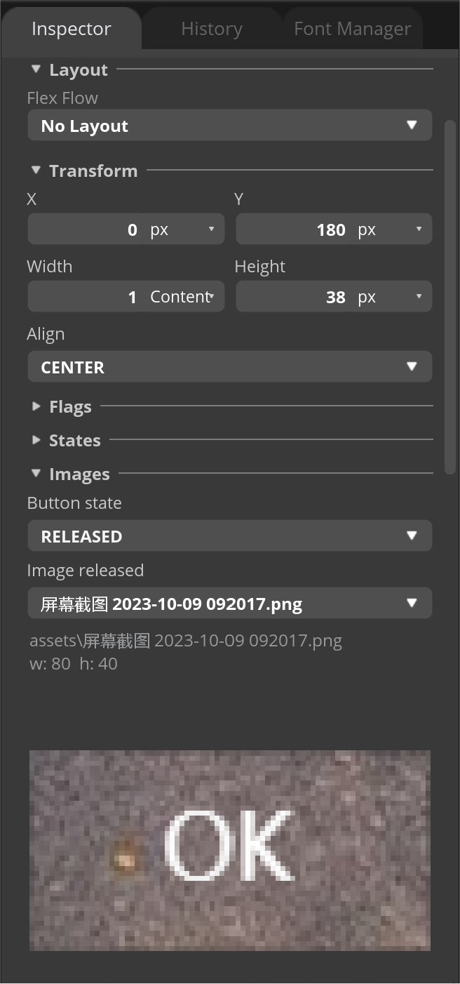
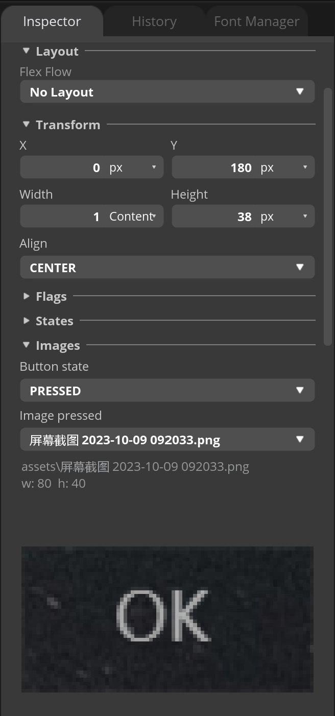
Click ImgButton2 and modify the parameter as shown in the following image:
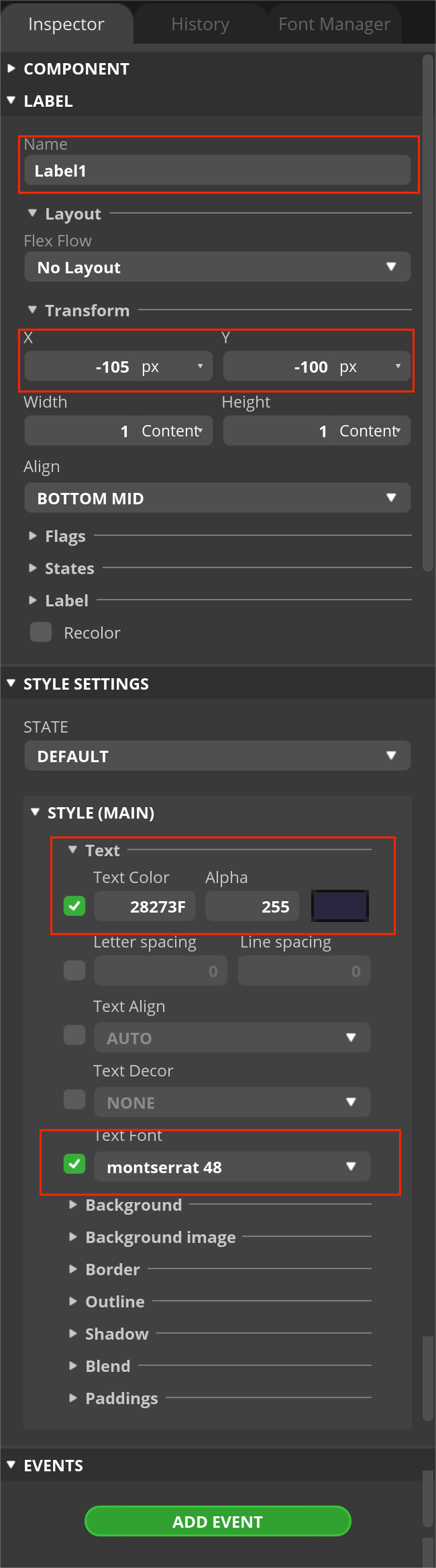
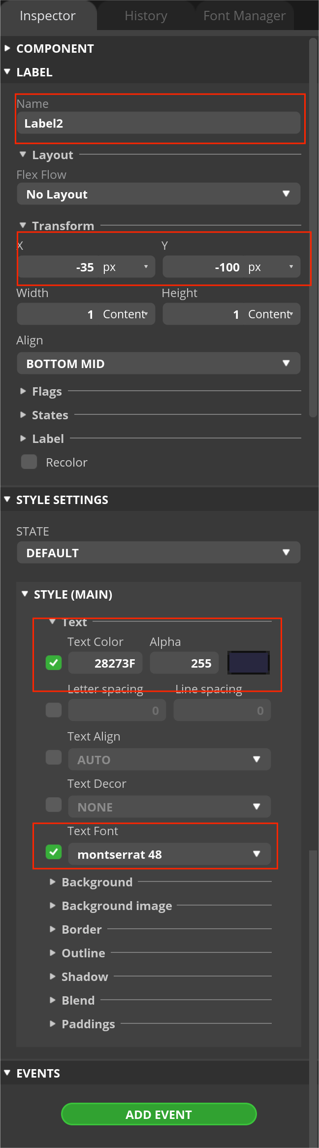
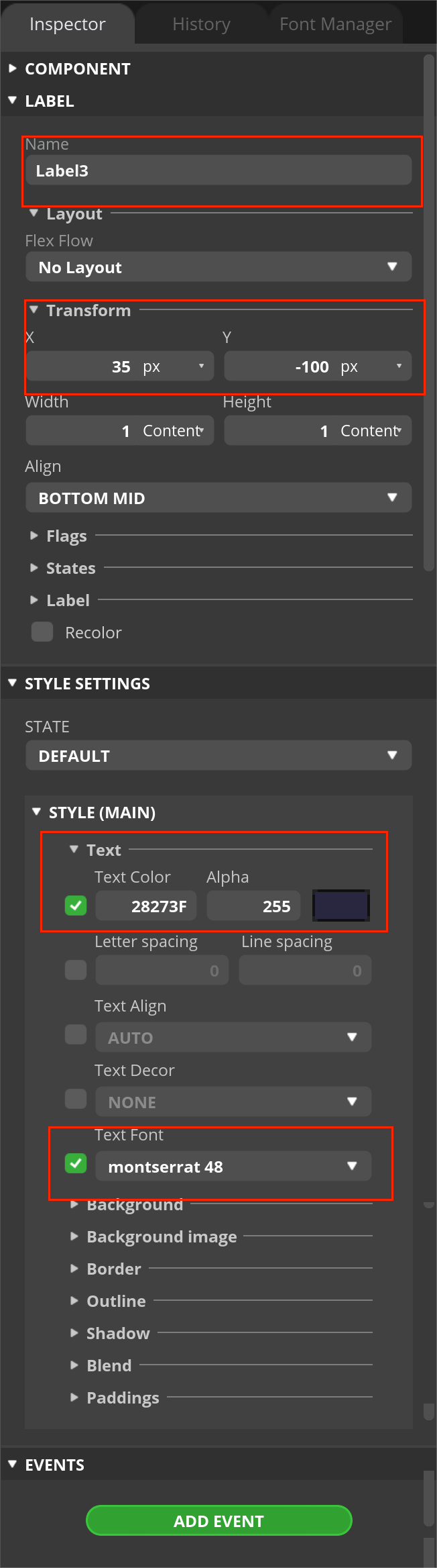
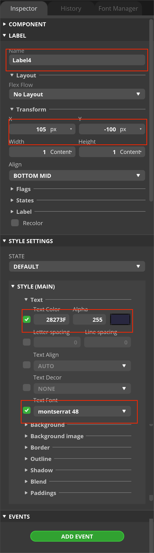
- Click Label1/Label2/Label3/Label4 and modify the parameter as shown in the following image:
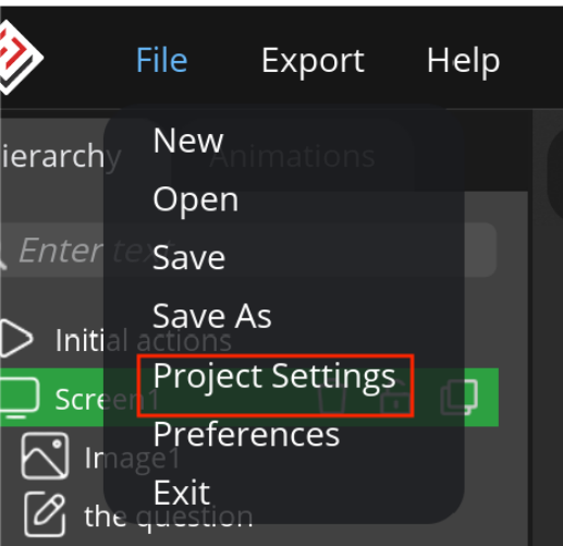
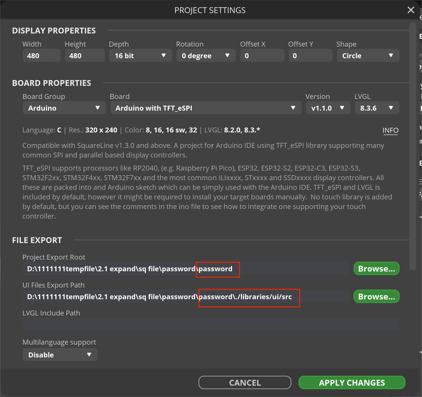
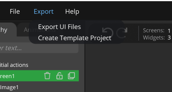
Finally, go to File>Projiect Settings, verify settings and save path, and click Create Template Project and Export UI File successively.
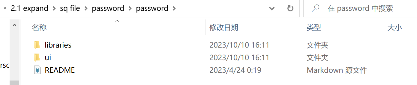
In the program export path, you will find two folders as in the following image. The "UI" folder has a single file named "UI.ino", which can be compiled in the Arduino IDE as a main program, when it is burned into the board after modifying code, the screen can display the UI image designed in the Squareline_Studio. Meanwhile, the "libraries" folder contains the library resources called in the program.
Hardware
To complete this tutorial you need the following parts:
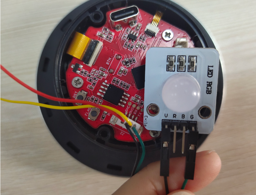
- MaTouch ESP32 S3 2.1 Rotary TFT with Touch
- LED_RGB
- connect J2 to LED: 3V3 to V and TX to G.
Firmware
The Arduino IDE supports ESP32 development board programming, before uploading the code, it is crucial to prepare the compilation environment for ESP32. If you haven't installed the ESP32 Board SDK yet, follow the steps to start quickly.
Install the ESP32 board in Arduino IDE
1.Install the Arduino IDE V1.8.10/V1.8.19.
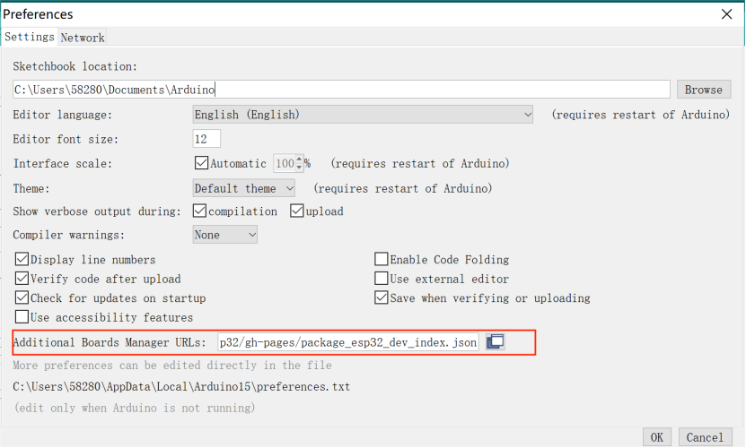
2.Additional Board Manager URLs:
Select "File>Preferences>settings>Additional Boards Manager URLs" to fill in the link:
https://dl.espressif.com/dl/package_esp32_index.json
https://raw.githubusercontent.com/espressif/arduino-esp32/gh-pages/package_esp32_dev_index.json
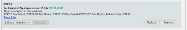
3.Boards Manager.
For the ESP32-S3 Development board version, we recommend using versions that have been verified, such as 2.0.6, which is more stable, and less prone to errors.
4.Choose the ESP32 Arduino
select and set the parameter in the Tools menu, as shown in the image:
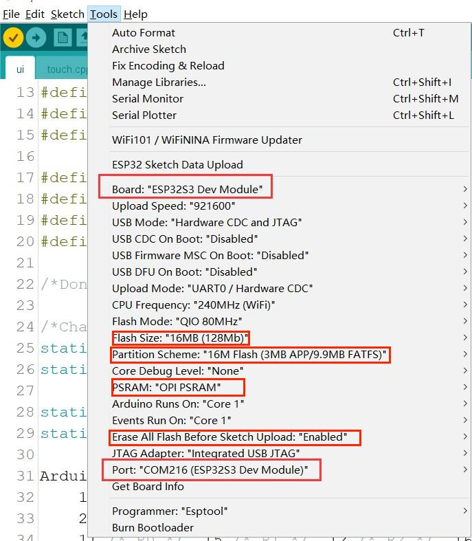 Choose the “ESP32-S3 Dev module”, flash size is 16MB, PSRAM is OPI PSRAM, Partition Scheme is 16M Flash (3MB APP/9.9MB FATFS), Erase ALL Flash Before Sketch Upload is Enabled, and choose the com.
Note: Different computers may have different port numbers when connecting to a development board. Please select the correct port number based on the development board you are connecting to.
Install the libraries and files necessary in Arduino IDE
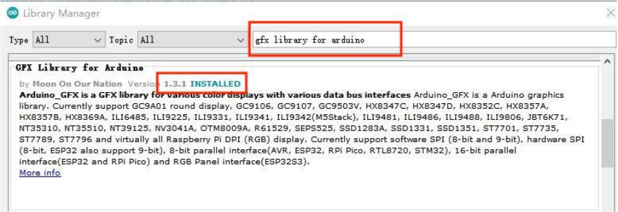
1. Install "GFX Library For Arduino" library(version 1.3.1)
Because The "TFT_eSPI" library doesn't support the ST7701 driver IC, we must use another library which is "GFX Library For Arduino" library to drive the theMaTouch ESP32 S3 2.1 Rotary TFT with Touch
Open the Arduino IDE, choose the >>tools>> Manage libraries> Search the "gfx library for Arduino" lib in the search box and install the library version 1.3.1.
2. Install "mf_Lvgl" library
unzip the "mf_Lvgl.zip", add it to the library file of Arduino, General Arduino library folder path for: C:/Users/Document/Arduino/libraries.
The lv_conf.h file is included in the library
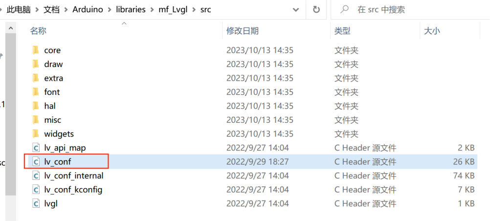
The lvgl_conf.h file is a setup file used to configure the lvgl library. It gets created when Squareline exports the project file. It contains options for turning on/off features, choosing colors, and setting up fonts.
/* clang-format off */
#if 1 /*Set it to "1" to enable content*/

/*Color depth: 1 (1 byte per pixel), 8 (RGB332), 16 (RGB565), 32 (ARGB8888)*/
#define LV_COLOR_DEPTH 16

/*Use a custom tick source that tells the elapsed time in milliseconds.
 *It removes the need to manually update the tick with `lv_tick_inc()`)*/
#define LV_TICK_CUSTOM 1
#if LV_TICK_CUSTOM
    #define LV_TICK_CUSTOM_INCLUDE "Arduino.h"         /*Header for the system time function*/
    #define LV_TICK_CUSTOM_SYS_TIME_EXPR (millis())    /*Expression evaluating to current system time in ms*/
#endif   /*LV_TICK_CUSTOM*/

/*Montserrat fonts with ASCII range and some symbols using bpp = 4
 *https://fonts.google.com/specimen/Montserrat*/
#define LV_FONT_MONTSERRAT_8  1
#define LV_FONT_MONTSERRAT_10 1
#define LV_FONT_MONTSERRAT_12 1
#define LV_FONT_MONTSERRAT_14 1
#define LV_FONT_MONTSERRAT_16 1
#define LV_FONT_MONTSERRAT_18 1
#define LV_FONT_MONTSERRAT_20 1
#define LV_FONT_MONTSERRAT_22 1
#define LV_FONT_MONTSERRAT_24 1
#define LV_FONT_MONTSERRAT_26 1
#define LV_FONT_MONTSERRAT_28 1
#define LV_FONT_MONTSERRAT_30 1
#define LV_FONT_MONTSERRAT_32 1
#define LV_FONT_MONTSERRAT_34 1
#define LV_FONT_MONTSERRAT_36 1
#define LV_FONT_MONTSERRAT_38 1
#define LV_FONT_MONTSERRAT_40 1
#define LV_FONT_MONTSERRAT_42 1
#define LV_FONT_MONTSERRAT_44 1
#define LV_FONT_MONTSERRAT_46 1
#define LV_FONT_MONTSERRAT_48 1
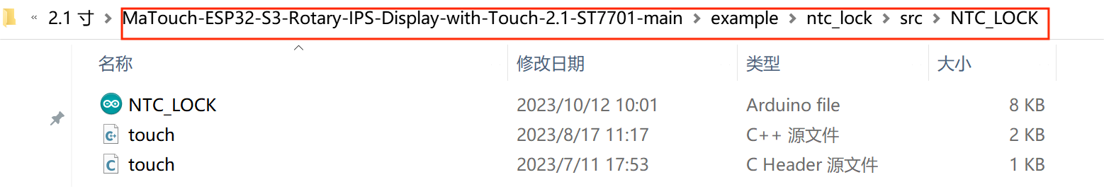
3. Install the scr.zip , unzip the file.Copy the “ui” folders to the library file of Arduino
Copy the “ui” library to the library file of Arduino, General Arduino library folder path for:
C:/Users/Document/Arduino/libraries.
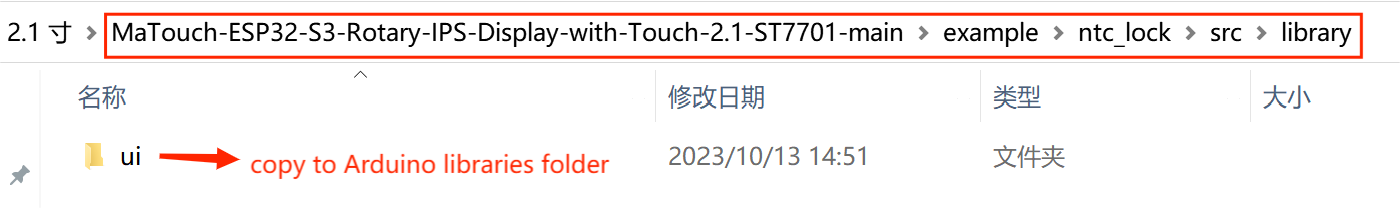 Note: If there is already an ui library in the library file of Arduino, delete it first and then add the new ui library.
Upload the code
choose the "ESP32-S3 Dev module", flash size is 16MB, PSRAM is OPI PSRAM, and choose the com. verify and upload the code.
If you want to use your own ui library, it is necessary to modify the code of ui.ino based on all the widget names you use in SquareLine, which is created when Squareline exports the project file.
How code works
- “touch.h” and “touch.cpp”
LVGL is a user interface library primarily focused on display functionality, but it lacks user interaction capabilities. So, we need something to help us touch or interact with the screen. “touch.h” and “touch.cpp” files can help figure out if the screen is touched, and where is touched, so we can do things like tapping on icons or buttons on the screen.
- Since we did not use the TFT_eSPI library, we need to delete or comment all the codes related to the TFT_eSPI library.
#include <TFT_eSPI.h>

TFT_eSPI tft = TFT_eSPI(screenWidth, screenHeight); /* TFT instance */

    tft.startWrite();
    tft.setAddrWindow( area->x1, area->y1, w, h );
    tft.pushColors( ( uint16_t * )&color_p->full, w * h, true );
    tft.endWrite();

    tft.begin();          /* TFT init */
    tft.setRotation( 3 ); /* Landscape orientation, flipped */
- Define the Header file of the libraries that have been used
#include <lvgl.h>
#include <Arduino_GFX_Library.h>
#include <Wire.h>
#include <ui.h>
#include "touch.h"
#include <HTTPClient.h>
Note: Please do not call "touch.h" at the top of the program, it can only be compiled after the gfx pin definition.
- Define screen touch-related pins, screen backlight pins, bottom detection pins, rotary encoder pins, and LED control pins
#define I2C_SDA_PIN 17
#define I2C_SCL_PIN 18
#define TOUCH_RST -1 // 38
#define TOUCH_IRQ -1 // 0

#define TFT_BL 38
#define BUTTON_PIN 14
#define ENCODER_CLK 13 // CLK
#define ENCODER_DT 10  // DT

#define RX_PIN 44
#define TX_PIN 43
- When we use the GFX library, we need to define the GFX Library For the Arduino Interface pin.
Arduino_ESP32RGBPanel *bus = new Arduino_ESP32RGBPanel(
    1 /* CS */, 46 /* SCK */, 0 /* SDA */,
    2 /* DE */, 42 /* VSYNC */, 3 /* HSYNC */, 45 /* PCLK */,
    11 /* R0 */, 15 /* R1 */, 12 /* R2 */, 16 /* R3 */, 21 /* R4 */,
    39 /* G0/P22 */, 7 /* G1/P23 */, 47 /* G2/P24 */, 8 /* G3/P25 */, 48 /* G4/P26 */, 9 /* G5 */,
    4 /* B0 */, 41 /* B1 */, 5 /* B2 */, 40 /* B3 */, 6 /* B4 */
);

// Uncomment for 2.1" round display
Arduino_ST7701_RGBPanel *gfx = new Arduino_ST7701_RGBPanel(
    bus, GFX_NOT_DEFINED /* RST */, 0 /* rotation */,
    false /* IPS */, 480 /* width */, 480 /* height */,
    st7701_type5_init_operations, sizeof(st7701_type5_init_operations),
    true /* BGR */,
    10 /* hsync_front_porch */, 8 /* hsync_pulse_width */, 50 /* hsync_back_porch */,
    10 /* vsync_front_porch */, 8 /* vsync_pulse_width */, 20 /* vsync_back_porch */);
- The goal of this code is to adjust the screen resolution. This resolution is created when Squareline exports the project file.
static const uint16_t screenWidth  = 480;
static const uint16_t screenHeight = 480;

static lv_disp_draw_buf_t draw_buf;
static lv_color_t buf[ screenWidth * screenHeight / 10 ];
- The NTP server is 120.25.108.11
const char *ntpServer = "120.25.108.11";
- Setting your network credentials
WiFi.begin("Makerfabs", "20160704");
- Getting the time from an NTP server
configTime((const long)(8 * 3600), 0, ntpServer);
- Display real time
void display_time()
{
    struct tm timeinfo;
    char temp[30];

    if (!getLocalTime(&timeinfo))
    {
        USBSerial.println("Failed to obtain time");
    }
    else
    {
        sprintf(temp, "%02d:%02d:%02d",
                timeinfo.tm_hour, timeinfo.tm_min, timeinfo.tm_sec);
        Serial.println(temp);
        lv_label_set_text(ui_Label16, temp);
    }
}
- Perform pin initialization
void pin_init()
{
    pinMode(TFT_BL, OUTPUT);
    digitalWrite(TFT_BL, HIGH);

    pinMode(RX_PIN, OUTPUT);
    pinMode(TX_PIN, OUTPUT);

    pinMode(ENCODER_CLK, INPUT_PULLUP);
    pinMode(ENCODER_DT, INPUT_PULLUP);
    old_State = digitalRead(ENCODER_CLK);

    attachInterrupt(ENCODER_CLK, encoder_irq, CHANGE);

    digitalWrite(RX_PIN, LOW);
    digitalWrite(TX_PIN, HIGH);

    Wire.begin(I2C_SDA_PIN, I2C_SCL_PIN);
}
- In my_disp_flush function, replace TFT functions which have been commented with the GFX function to achieve pixel reading and writing operations on the screen
/* Display flushing */
void my_disp_flush( lv_disp_drv_t *disp, const lv_area_t *area, lv_color_t *color_p )
{
    uint32_t w = ( area->x2 - area->x1 + 1 );
    uint32_t h = ( area->y2 - area->y1 + 1 );

//    tft.startWrite();
//    tft.setAddrWindow( area->x1, area->y1, w, h );
//    tft.pushColors( ( uint16_t * )&color_p->full, w * h, true );
//    tft.endWrite();

#if (LV_COLOR_16_SWAP != 0)
    gfx->draw16bitBeRGBBitmap(area->x1, area->y1, (uint16_t *)&color_p->full, w, h);
#else
    gfx->draw16bitRGBBitmap(area->x1, area->y1, (uint16_t *)&color_p->full, w, h);
#endif

    lv_disp_flush_ready( disp );
}
- Modify the touchpad function according to the pre-set functions in touch.h, and pass the state of the touchpad to the LVGL graphics library.
void my_touchpad_read( lv_indev_drv_t * indev_driver, lv_indev_data_t * data )
{
   int touchX = 0, touchY = 0;

    if (read_touch(&touchX, &touchY) == 1)
    {
        data->state = LV_INDEV_STATE_PR;

        data->point.x = (uint16_t)touchX;
        data->point.y = (uint16_t)touchY;
    }
    else
    {
        data->state = LV_INDEV_STATE_REL;
    }
}
- Initialize various display-related configurations.
/*Initialize the display*/
static lv_disp_drv_t disp_drv;
lv_disp_drv_init( &disp_drv );
/*Change the following line to your display resolution*/
disp_drv.hor_res = screenWidth;
disp_drv.ver_res = screenHeight;
disp_drv.flush_cb = my_disp_flush;
disp_drv.draw_buf = &draw_buf;
lv_disp_drv_register( &disp_drv );

/*Initialize the (dummy) input device driver*/
static lv_indev_drv_t indev_drv;
lv_indev_drv_init( &indev_drv );
indev_drv.type = LV_INDEV_TYPE_POINTER;
indev_drv.read_cb = my_touchpad_read;
lv_indev_drv_register( &indev_drv );
- Trigger an interrupt whenever the pin ENCODER_CLK changes value, get the value of the counter
attachInterrupt(ENCODER_CLK, encoder_irq, CHANGE);
void encoder_irq()
{
    State = digitalRead(ENCODER_CLK);
    if (State != old_State)
    {
        if (digitalRead(ENCODER_DT) == State)
        {
            counter++;
        }
        else
        {
            counter--;
        }
    }
    old_State = State; // the first position was changed
}
- Get the value of arc_coun, let the value of ui-Arc1 be changed with the encoder, cycled from 0 to 9
lv_arc_set_value(ui_Arc1, (int)arc_coun);
void cal_encoder()
{
    USBSerial.print("Position: ");
    USBSerial.println(counter);

    target_count = (counter % 20) / 2;
    if (target_count < 0)
    {
        target_count = (counter % 20) / 2 + 10;
    }

    if (target_count > arc_coun)
        arc_coun++;
    else if (target_count < arc_coun)
        arc_coun--;

    USBSerial.print("arc_Position: ");
    USBSerial.println(arc_coun);
}
- Make the value of ui_Label the same as the value of ui_Arc.
_ui_arc_set_text_value(ui_Label1, ui_Arc1, "", "");
- Rotate the encoder to change the value of ui_Label1/2/3/4 and press the screen to confirm.
    if (label_flag != 0)
        if ((millis() - runtime) > 100)
        {

            display_time();

            cal_encoder();
            lv_arc_set_value(ui_Arc1, (int)arc_coun);
            runtime = millis();
        }

    if (label_flag == 1)
    {
        _ui_arc_set_text_value(ui_Label1, ui_Arc1, "", "");
        if (arc_coun == 2)
        {
            if (digitalRead(BUTTON_PIN) == 0)
            {
                USBSerial.println("Button Press");
                while (digitalRead(BUTTON_PIN) == 0) // 不松开不进入下一个切换
                {
                    delay(50);
                }
                label_flag = 2;
            }
        }
    }

    if (label_flag == 2)
    {
        _ui_arc_set_text_value(ui_Label2, ui_Arc1, "", "");
        if (arc_coun == 4)
        {
            if (digitalRead(BUTTON_PIN) == 0)
            {
                USBSerial.println("Button Press");
                while (digitalRead(BUTTON_PIN) == 0) // 不松开不进入下一个切换
                {
                    delay(50);
                }
                label_flag = 3;
            }
        }
    }
    if (label_flag == 3)
    {
        _ui_arc_set_text_value(ui_Label3, ui_Arc1, "", "");
        if (arc_coun == 6)
        {
            if (digitalRead(BUTTON_PIN) == 0)
            {
                USBSerial.println("Button Press");
                while (digitalRead(BUTTON_PIN) == 0) // 不松开不进入下一个切换
                {
                    delay(50);
                }
                label_flag = 4;
            }
        }
    }
    if (label_flag == 4)
    {
        _ui_arc_set_text_value(ui_Label4, ui_Arc1, "", "");
        if (arc_coun == 8)
        {
            if (digitalRead(BUTTON_PIN) == 0)
            {
                USBSerial.println("Button Press");
                while (digitalRead(BUTTON_PIN) == 0) // 不松开不进入下一个切换
                {
                    delay(50);
                }

                label_flag = 0;
                _ui_state_modify(ui_ImgButton2, LV_STATE_DISABLED, _UI_MODIFY_STATE_REMOVE);
            }
        }
    }
- Change the value of the LED pin to make the green light come on
void unlock()
{
    USBSerial.println("Unlock...");
    digitalWrite(RX_PIN, HIGH);
    digitalWrite(TX_PIN, LOW);
}
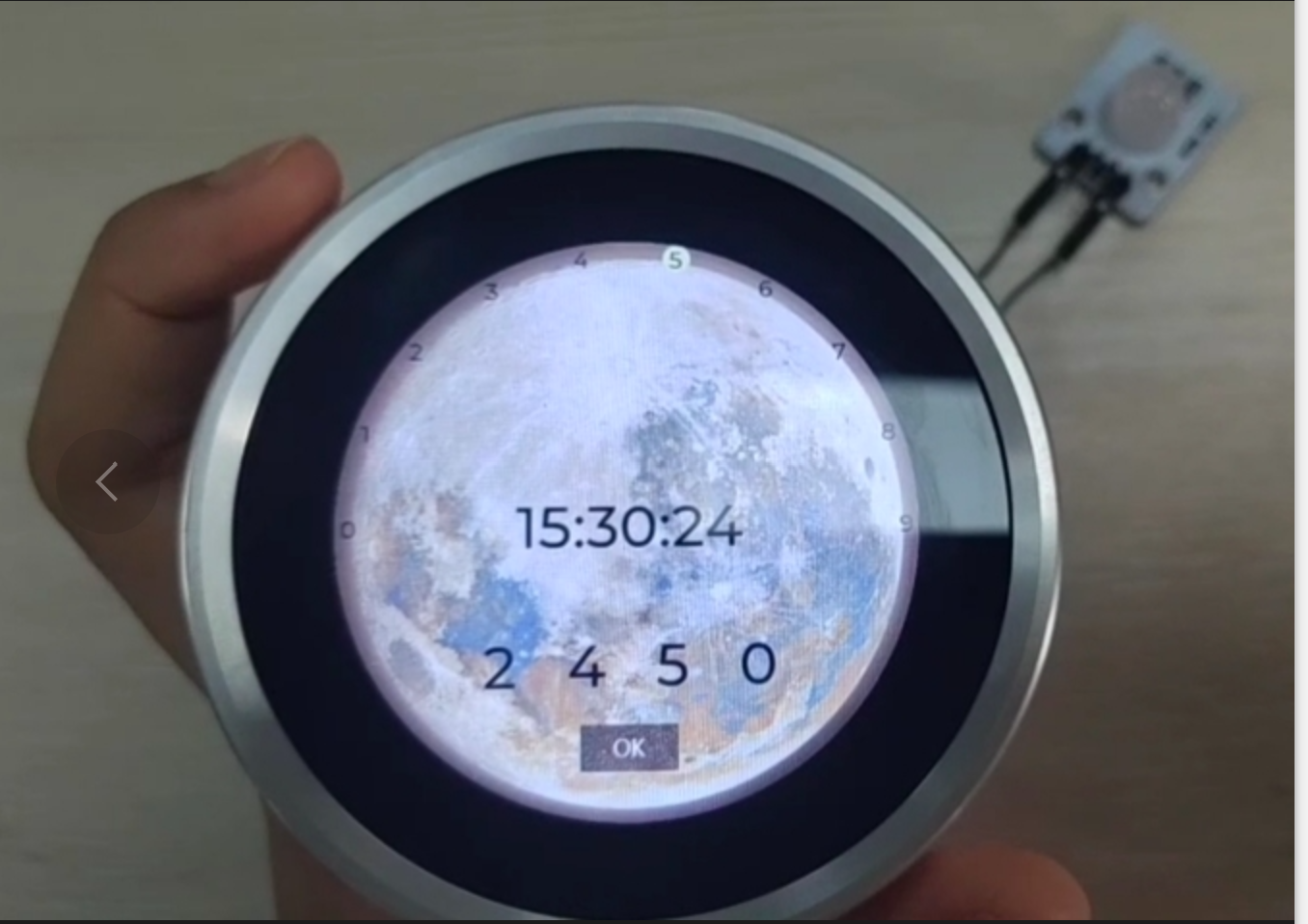
Result
After successfully uploading the code, users will see the Squareline UI displayed on the screen. We can interact with the UI by tapping or dragging the screen, utilizing the touch functionality.
FAQ
You can list your questions here or contact techsupport@makerfabs.com for technology support. Detailed descriptions of your question will help to solve your question.
Question 1: Do I need to modify something in the ui library folder? Answer: users just need to copy the ui library to the Arduino library folder.