MaTouch ESP32 S3 2.1 Rotary TFT with Touch
Introduction
This wiki shows the basic usage of MaTouch ESP32-S3 Rotary TFT Display with Touch 2.1" ST7701. As an example, we’ll drive the LCD shows something using the RGB565 with 3-wire SPI interface, and show you how to install the library and try sample code to write text or image on the LCD, detect the button and rotary decoder. The ESP32-S3 we’ll be programmed using Arduino IDE. Meanwhile, it supports Square Line IDE too, it can run the LVGL.
Features
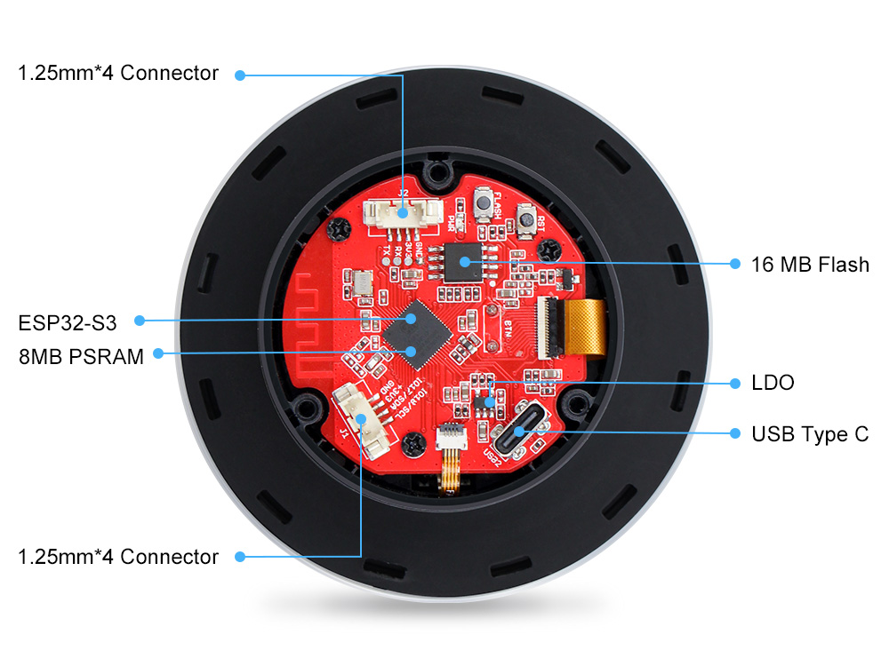
Controller: ESP32-S3, PCB Antenna
Wireless: WiFi& Bluetooth 5.0
Flash: 16MB Flash
RAM: 8MB PSRAM
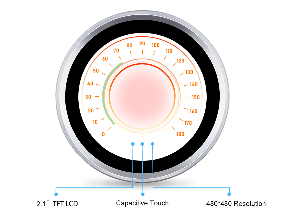
LCD: 2.1 inch TFT LCD
Resolution: 480 * 480
Color: 65K
LCD interface: RGB565 + 3-wire SPI
LCD Driver:ST7701S
Touch Panel: Capacitive
Touch Panel Driver: CST826
USB: native USB Type-C
USB to UART Chip: No
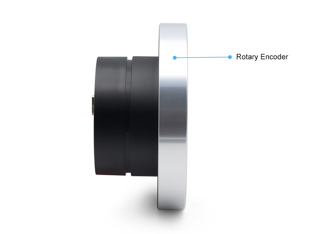
Rotary Encoder and Press button: Yes
Button: Flash button and reset button
More interface: I2C; UART(1.25mm4P Connector)
Backlight Controller: Yes
MicroSD: No
Audio: No
Arduino Support: Yes
LVGL/SquareLine Compatible: Yes
Type-C Power Delivery: Not Supported
Power Supply: USB Type-C 5.0V(4.0V~5.25V)
Operation temperature: -40℃ to +85℃
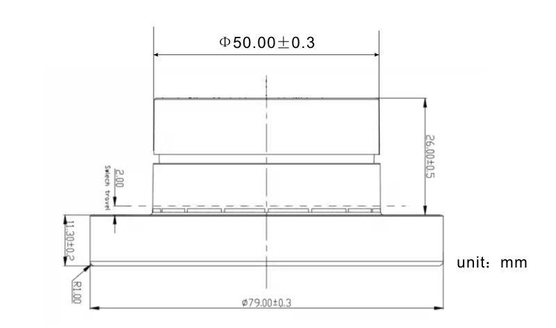
Dimension: 71.27mm71.27mm
Hardware
Usage in Arduino IDE
Display and Touch Test
Note: The same version of the library and package is recommended in case of upgrades make unexpected errors.
1,Install the Arduino IDE V1.8.10/V1.8.19.
Note:There are so many versions of Arduino and they have many differences, some of them don't have version 2.0.6 of the ESP32 Boards
2,Install the ESP32 board package
version 2.0.6 and version 2.0.10 has been tested and recommended.
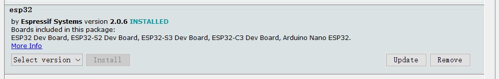 All projects are based on the ESP32-S3 development board, guaranteeing higher compatibility and stability.If you haven't installed the ESP32 Board SDK yet, follow the steps in this guide to get started quickly .
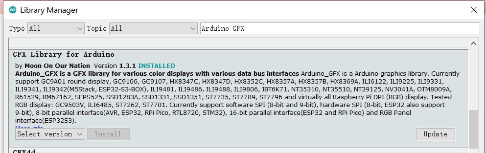
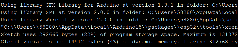
3,Install GFX Library for Arduino V1.3.1
Because The "TFT_eSPI" library doesn't support the ST7701 driver IC, we must use another library which is "GFX Library For Arduino" library to drive the theMaTouch ESP32 S3 2.1 Rotary TFT with Touch
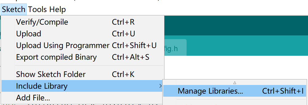
Open the Arduino IDE, choose the >>tools>> Manage libraries> Search the "gfx library for Arduino" lib in the search box and install the library version 1.3.1.
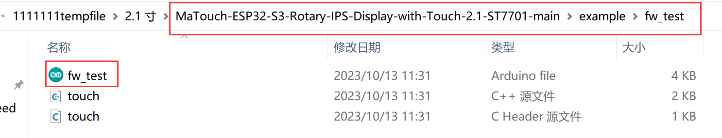
4, Download the MaTouch-ESP32-S3-Rotary-IPS-Display-with-Touch-2.1-ST7701.zip , unzip the file, open the code fw_test.ino.
5,Now, compile and upload the code to ESP32-S3.
- Plug your Matouch 2.1” board in your computer;
-
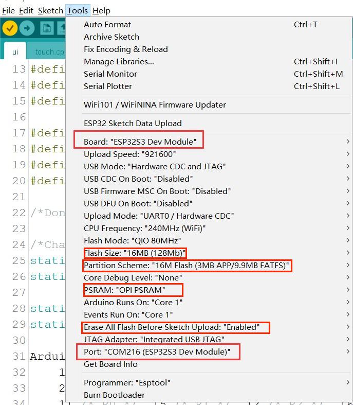
In the Arduino IDE select your board in Tools > Board (in our case we’re using the ESP32S3 Dev Module);
-
Select the COM port in Tools > Port.
Note: Different computers may have different port numbers when connecting to a development board. Please select the correct port number based on the development board you are connecting to.
Choose the "ESP32-S3 Dev module", flash size is 16MB, PSRAM is OPI PSRAM, Partition Scheme is 16M Flash (3MB APP/9.9MB FATFS), Erase ALL Flash Before Sketch Upload is Enabled, and choose the com. verify and upload the code.
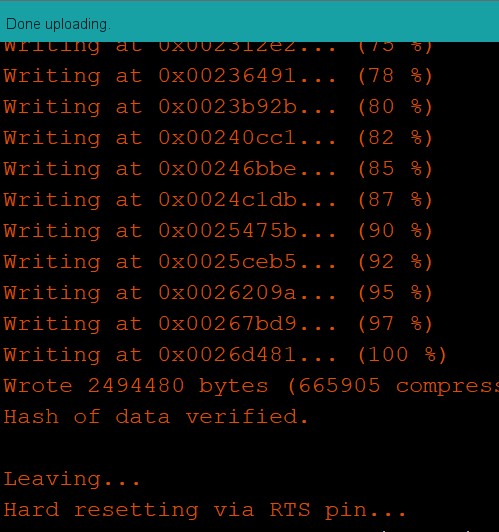
- Click the Upload button in the Arduino IDE and wait a few times while the code compiles and uploads to your board.
-
Press the reset button after the “Done uploading” message.
-
Now you can test it if your board working properly. You can touch the capacitive panel to get the X/Y location.
Display and Touch Test with LVGL
Note: The same version of the library and package is recommended in case of upgrades make unexpected errors.
1,Install the Arduino IDE V1.8.10/V1.8.19.
Note:There are so many versions of Arduino and they have many differences, some of them don't have version 2.0.6 of the ESP32 Boards
2,Install the ESP32 board package version 2.0.6
All projects are based on the ESP32-S3 development board, guaranteeing higher compatibility and stability.If you haven't installed the ESP32 Board SDK yet, follow the steps in this guide to get started quickly .
3,Install GFX Library for Arduino V1.3.1
Because The "TFT_eSPI" library doesn't support the ST7701 driver IC, we must use another library which is "GFX Library For Arduino" library to drive the theMaTouch ESP32 S3 2.1 Rotary TFT with Touch
Open the Arduino IDE, choose the >>tools>> Manage libraries> Search the "gfx library for Arduino" lib in the search box and install the library version 1.3.1.
4, Install "mf_Lvgl" library
unzip the "mf_Lvgl.zip", and copy it to the library file of Arduino, General Arduino library folder path for: C:/Users/Document/Arduino/libraries.
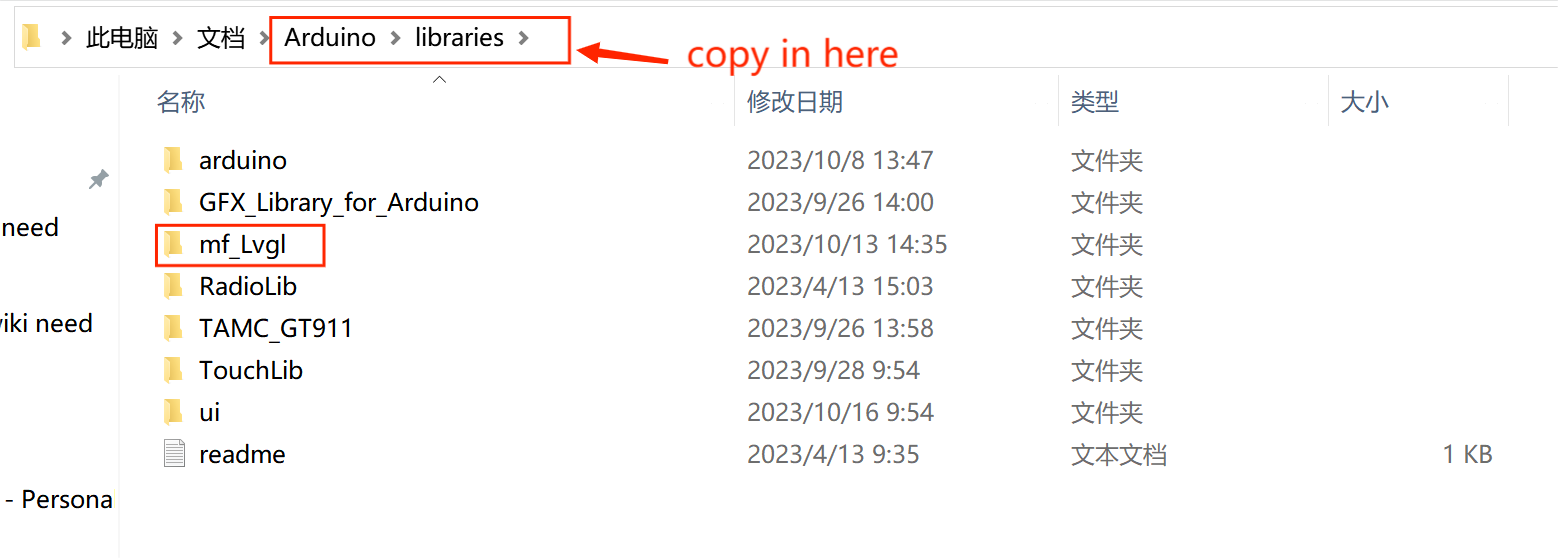
And it is also OK to open the sketch>include library> ADD.ZIP library,choose the download path of mf_Lvgl to add the library to the Arduino library file.
The lv_conf.h file is included in the library
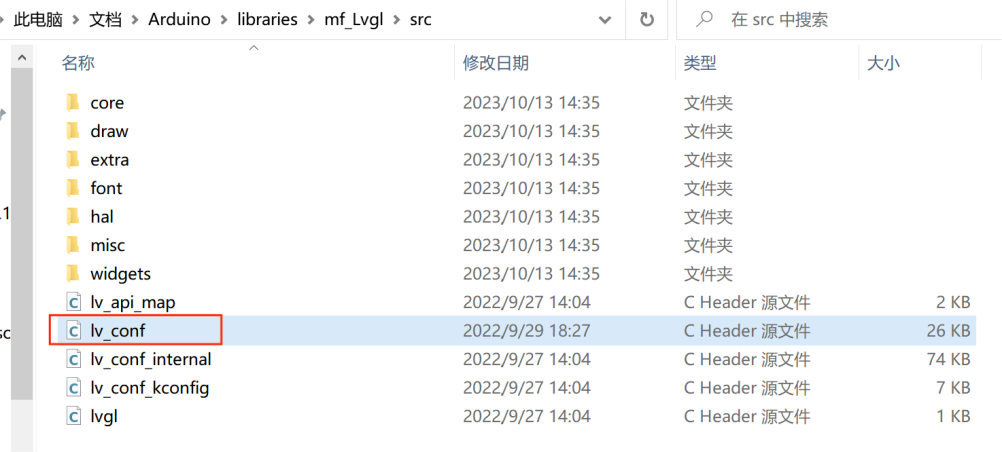
The lvgl_conf.h file is a setup file used to configure the lvgl library. It gets created when Squareline exports the project file. It contains options for turning on/off features, choosing colors, and setting up fonts.
/* clang-format off */
#if 1 /*Set it to "1" to enable content*/

/*Color depth: 1 (1 byte per pixel), 8 (RGB332), 16 (RGB565), 32 (ARGB8888)*/
#define LV_COLOR_DEPTH 16

/*Use a custom tick source that tells the elapsed time in milliseconds.
 *It removes the need to manually update the tick with `lv_tick_inc()`)*/
#define LV_TICK_CUSTOM 1
#if LV_TICK_CUSTOM
    #define LV_TICK_CUSTOM_INCLUDE "Arduino.h"         /*Header for the system time function*/
    #define LV_TICK_CUSTOM_SYS_TIME_EXPR (millis())    /*Expression evaluating to current system time in ms*/
#endif   /*LV_TICK_CUSTOM*/

/*Montserrat fonts with ASCII range and some symbols using bpp = 4
 *https://fonts.google.com/specimen/Montserrat*/
#define LV_FONT_MONTSERRAT_8  1
#define LV_FONT_MONTSERRAT_10 1
#define LV_FONT_MONTSERRAT_12 1
#define LV_FONT_MONTSERRAT_14 1
#define LV_FONT_MONTSERRAT_16 1
#define LV_FONT_MONTSERRAT_18 1
#define LV_FONT_MONTSERRAT_20 1
#define LV_FONT_MONTSERRAT_22 1
#define LV_FONT_MONTSERRAT_24 1
#define LV_FONT_MONTSERRAT_26 1
#define LV_FONT_MONTSERRAT_28 1
#define LV_FONT_MONTSERRAT_30 1
#define LV_FONT_MONTSERRAT_32 1
#define LV_FONT_MONTSERRAT_34 1
#define LV_FONT_MONTSERRAT_36 1
#define LV_FONT_MONTSERRAT_38 1
#define LV_FONT_MONTSERRAT_40 1
#define LV_FONT_MONTSERRAT_42 1
#define LV_FONT_MONTSERRAT_44 1
#define LV_FONT_MONTSERRAT_46 1
#define LV_FONT_MONTSERRAT_48 1
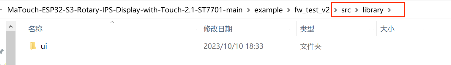
5,Install the scr.zip , unzip the file
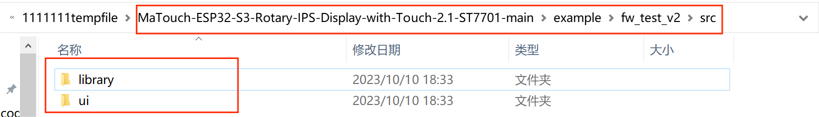
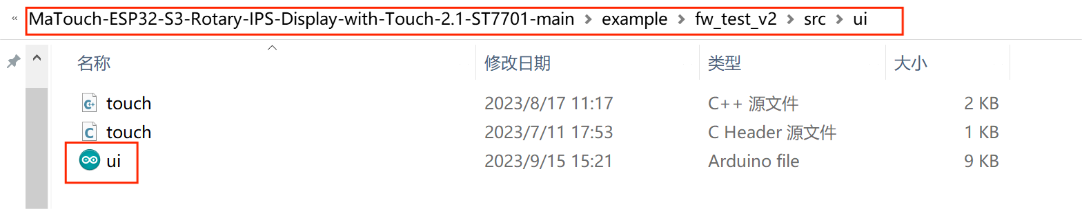
6,Copy the ui folder in the library to Arduino library directory, it often located in C:\Users\Administrator\Documents\Arduino\libraries:
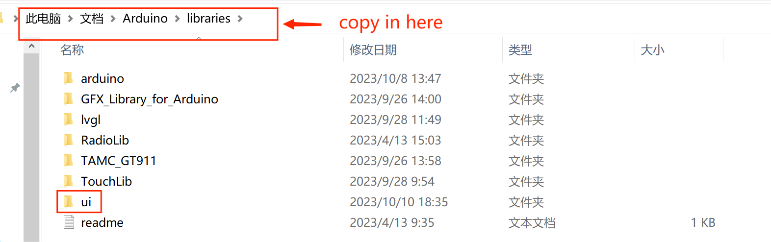
7,Open the code ui.ino.
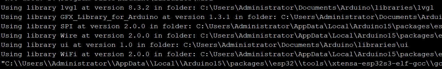
8,Now, compile and upload the code to ESP32-S3.
- Plug your Matouch 2.1” board in your computer;
-
In the Arduino IDE select your board in Tools > Board (in our case we’re using the ESP32S3 Dev Module);
-
Select the COM port in Tools > Port.
Note: Different computers may have different port numbers when connecting to a development board. Please select the correct port number based on the development board you are connecting to.
Choose the "ESP32-S3 Dev module", flash size is 16MB, PSRAM is OPI PSRAM, Partition Scheme is 16M Flash (3MB APP/9.9MB FATFS), Erase ALL Flash Before Sketch Upload is Enabled, and choose the com. verify and upload the code.
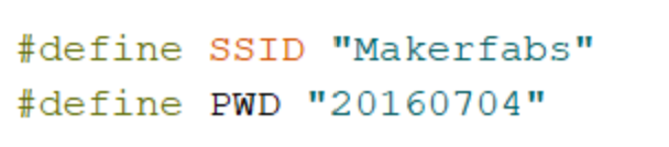
- Setting your network credentials
- Click the Upload button in the Arduino IDE and wait a few times while the code compiles and uploads to your board.
-
Press the reset button after the “Done uploading” message.
-
Results Show
Now you can test it if your board working properly. You can touch the capacitive panel to get the X/Y location, press the display to a new UI, rotate screen to increase or decrease the progress bar.
Usage in VS Code&PlatformIO
The goal of thissection is to demonstrate how simple it is to use PlatformIO IDE for VSCode to develop, run and debug a basic project with the Arduino framework for the MaTouch ESP32-S3 Rotary TFT Display with Touch 2.1" ST7701 board.
-
Downloaded and installed PlatformIO IDE for VSCode
-
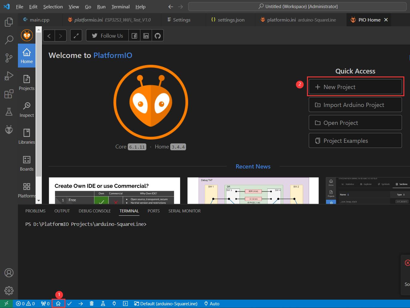
We need to create a new project using the PlatformIO Home Page (to open this page, just press the Home icon on the toolbar):
-
Input the project name. Select Espressif ESP32-S3 Dev Module as a development board, Arduino as a framework and a path to the project location (or use the default one):
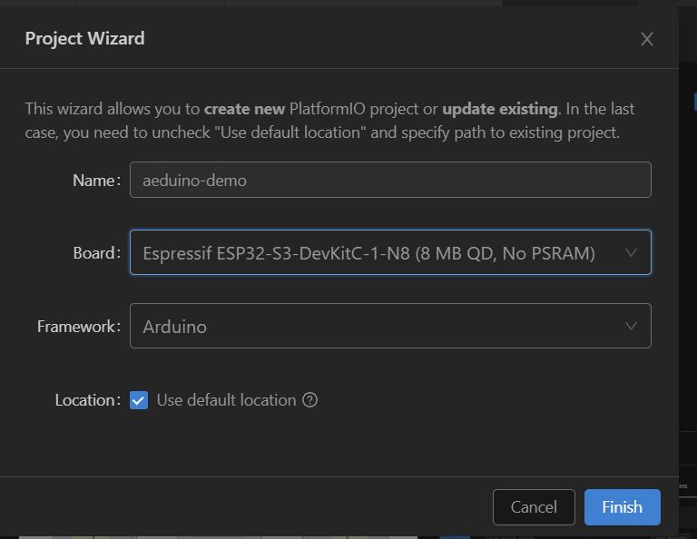
Processing the selected project may take some time at first time(PlatformIO will download and install all required packages). After that, we have a fully configured project that is ready for developing code with the Arduino framework.
Note it may be wait a while according to your network quality, even you need to try a few times in terrible network situation.
-
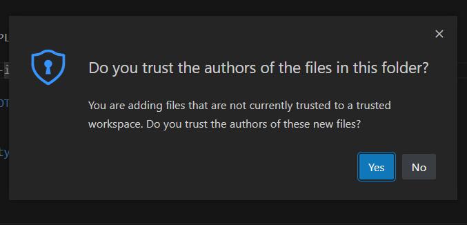
Click Yes if it shows the boxdialog box.
-
Let’s add some actual code to the project. Firstly, we open a default main file named main.cpp in the src folder and replace its content with following:
#include <Arduino.h>

#define LOG_OUT USBSerial  //Serial

int i=0;

void setup()
{
    LOG_OUT.begin(9600);
}

void loop()
{
    i++;
    LOG_OUT.print("Hello world! #");
    LOG_OUT.println(i);
    delay(1000);
}
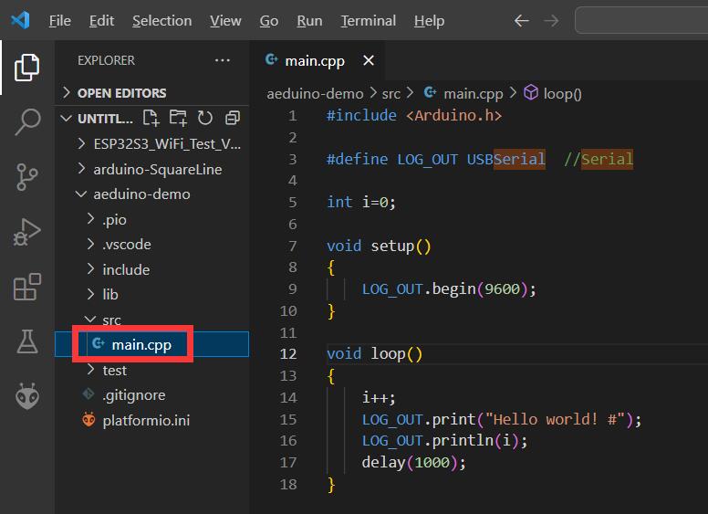
We have now created a simple project ready for compiling and uploading.
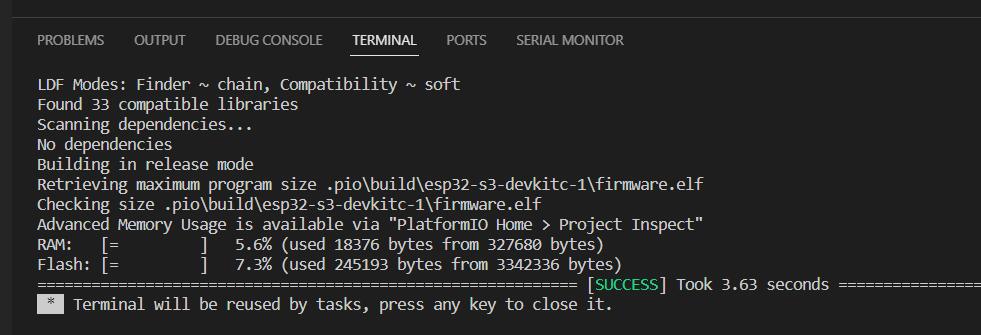
- Now we can build the project. There are several ways to compile firmware:
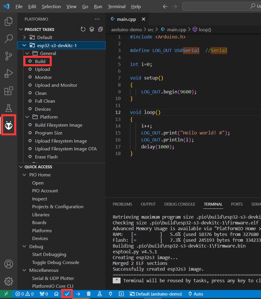
If everything went well, we should see a Success message in the terminal window:
- Upload the firmware to the board:
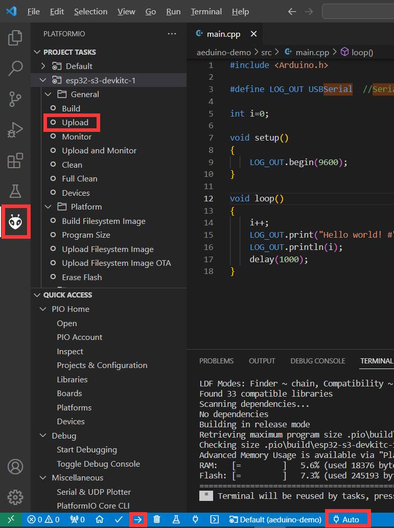
The Serial port is often auto detected by IDE, you can also change it.
-
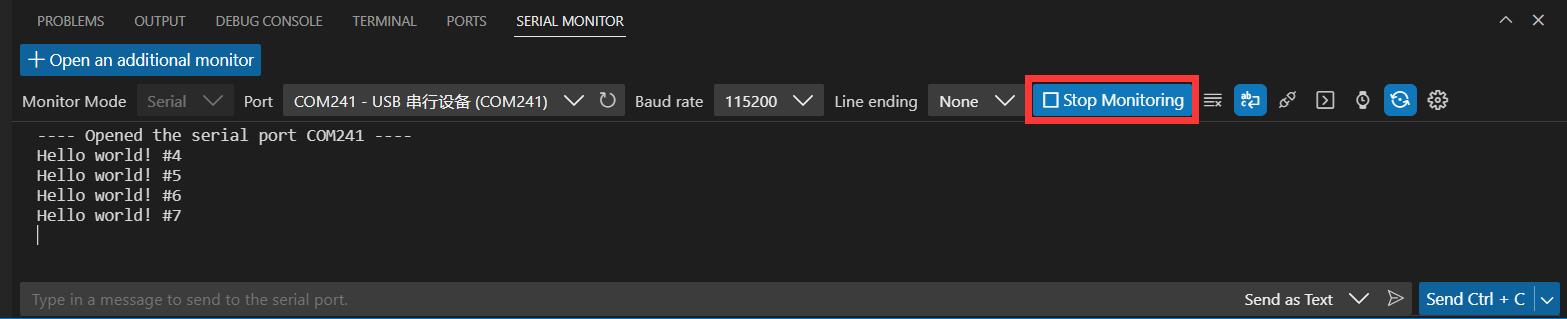
After uploading, we need to check if the firmware is uploaded correctly. To do this, open the serial monitor[By Clicking Start Monitoring] and check that the message from the board is received.
-
If the firmware works as expected, the message from the board can be observed in the terminal window:
FAQ
Any technical questions you can contact techsupport@makerfabs.com for technology support. Detailed descriptions of your question will be helped to solve your question.
-
Q1: Why the display fails to respond sometimes I touch?
A1: The touching interface is loose, please reconnect it. -
Q2: I get the error "no matching function for call to 'Arduino_ESP32RGBPanel::Arduino_ESP32RGBPanel(int, int, int, int, int, int, int, int, int, int, int, int, int, int, int, int, int, int, int, int, int, int, int)'); ^" when I compile the code, how to solve it?
 A2: Mabe you use the newest ArduinoGFX v1.3.8 not the tested v1.3.1. The oringinal code need to make some changes to support v1.3.8 as below:
#if 0  //for Arduino_GFX_Library v1.3.1
Arduino_ESP32RGBPanel *bus = new Arduino_ESP32RGBPanel(
  1 /* CS */, 46 /* SCK */, 0 /* SDA */,
  2 /* DE */, 42/* VSYNC */, 3 /* HSYNC */, 45 /* PCLK */,
  11 /* R0 */, 15 /* R1 */, 12 /* R2 */, 16 /* R3 */, 21 /* R4 */,
  39 /* G0/P22 */, 7 /* G1/P23 */, 47 /* G2/P24 */, 8 /* G3/P25 */, 48 /* G4/P26 */, 9 /* G5 */,
  4 /* B0 */, 41 /* B1 */, 5 /* B2 */, 40 /* B3 */, 6 /* B4 */
);

// Uncomment for 2.1" round display
 Arduino_ST7701_RGBPanel *gfx = new Arduino_ST7701_RGBPanel(
     bus, GFX_NOT_DEFINED /* RST */, 0 /* rotation */,
     false /* IPS */, 480 /* width */, 480 /* height */,
     st7701_type5_init_operations, sizeof(st7701_type5_init_operations),
     true /* BGR */,
     10 /* hsync_front_porch */, 8 /* hsync_pulse_width */, 50 /* hsync_back_porch */,
     10 /* vsync_front_porch */, 8 /* vsync_pulse_width */, 20 /* vsync_back_porch */);
#endif  //end of  for Arduino_GFX_Library v1.3.1

#if 1 //for Arduino_GFX_Library v1.3.6/v1.3.8
Arduino_DataBus *bus = new Arduino_SWSPI(
    GFX_NOT_DEFINED /* DC */, 1 /* CS */,
    46 /* SCK */, 0 /* MOSI */, GFX_NOT_DEFINED /* MISO */);

Arduino_ESP32RGBPanel *rgbpanel = new Arduino_ESP32RGBPanel(
    2 /* DE */, 42/* VSYNC */, 3 /* HSYNC */, 45 /* PCLK */,
    4 /* R0 */, 41 /* R1 */, 5 /* R2 */, 40 /* R3 */, 6 /* R4 */,
    39 /* G0/P22 */, 7 /* G1/P23 */, 47 /* G2/P24 */, 8 /* G3/P25 */, 48 /* G4/P26 */, 9 /* G5 */,
    11 /* B0 */, 15 /* B1 */, 12 /* B2 */, 16 /* B3 */, 21 /* B4 */,
    1 /* hsync_polarity */, 10 /* hsync_front_porch */, 8 /* hsync_pulse_width */, 50 /* hsync_back_porch */,
    1 /* vsync_polarity */, 10 /* vsync_front_porch */, 8 /* vsync_pulse_width */, 20 /* vsync_back_porch */);


Arduino_RGB_Display *gfx = new Arduino_RGB_Display(
    480 /* width */, 480 /* height */, rgbpanel, 0 /* rotation */, true /* auto_flush */,
    bus, GFX_NOT_DEFINED /* RST */, st7701_type5_init_operations, sizeof(st7701_type5_init_operations));
#endif   //End of for Arduino_GFX_Library v1.3.6/v1.3.8
- Q3: I get the failed message from serial after I uploaded the code to the board: no mem for frame buffer ESP_ERROR_CHECK failed: esp_err_t 0x101 (ESP_ERR_NO_MEM) at 0x4037af3c, the screen shows nothing. What's wrong? A3: There is no enough memory, you must select PSRAM "OPIPSRAM": in Arduino IDE. As the same, 16MB Flash and 3MB APP/9.9MB FATFS are also recommannded for huge application.