ESP8266 WIFI Shield
Introduction
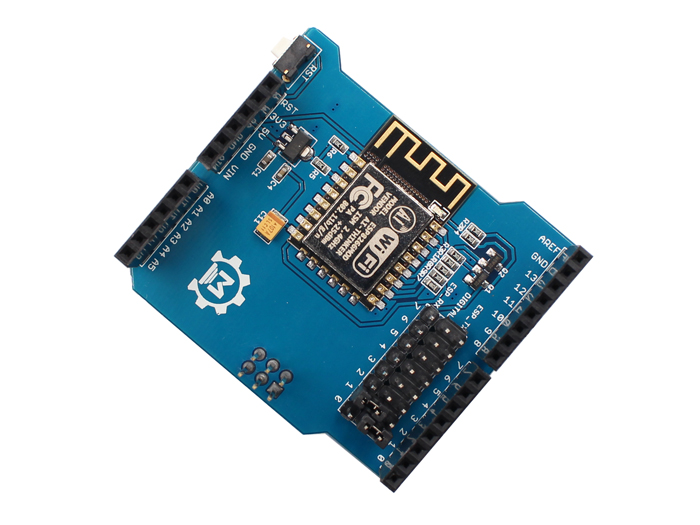
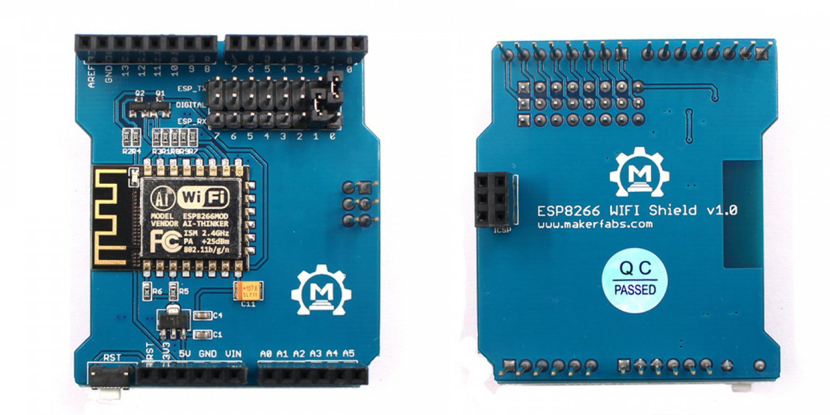
ESP8266 WIFI Shield is a cost-effective and highly integrated UART-WiFi module for IoT applications. It has excellent dimensions and ULP technology compared to other similar modules. The module is specially designed for mobile devices and the Internet of Things (IoT). This WiFi Shield is based on ESP-12F, which is the new version of the ESP-12 with the WiFi chip ESP8266. With this Shield, you can make your Arduino easy to connect to the network and control your device anywhere. Just communication via UART interface and control by AT command.
Model: OAS8266WF
Features
- Support wireless 802.11 b/g/n standard
- Support the STA/AP/STA + AP three work modes
- Built-in TCP/IP protocol stack, and support multiple TCP Client connection
- Support rich Socket the AT command
- Support UART/GPIO data communication interface
- Support Smart Link intelligent networking
- Support remote firmware update (OTA)
Interface Function
The use of in-line coupling and development board serial communication, to avoid the impact of jumper
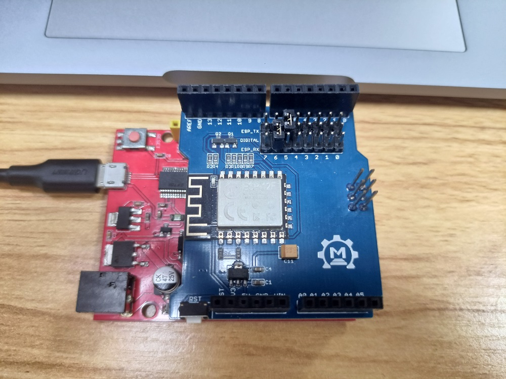
Assembly
Plug into Arduino or Maduino, and connect the USB to the PC. You must put on the jumper cap as shown in the picture.
Note: If we communicate with Arduino UNO through serial ports, making the WiFi Shield change the baud rate to 9600bps will make the communication more successful and prevent garbled characters. Please click on the "ESP8266 WiFi Shield Firmware Upgrade V1.0" and it will tell you how to do.
Load Demo
Wifi Test
- You can get the code from the Resources link.
Note: Because wifi shield default factory set baud rate is 115200, when we use 9600, we need to modify its baud rate by AT command. Please click on the "ESP8266 WiFi Shield Firmware Upgrade V1.0" and it will tell you how to do.
- Open Serial_Wifi.ino with Arduino IDE. Select the Arduino Uno board and the USB port in Tools.
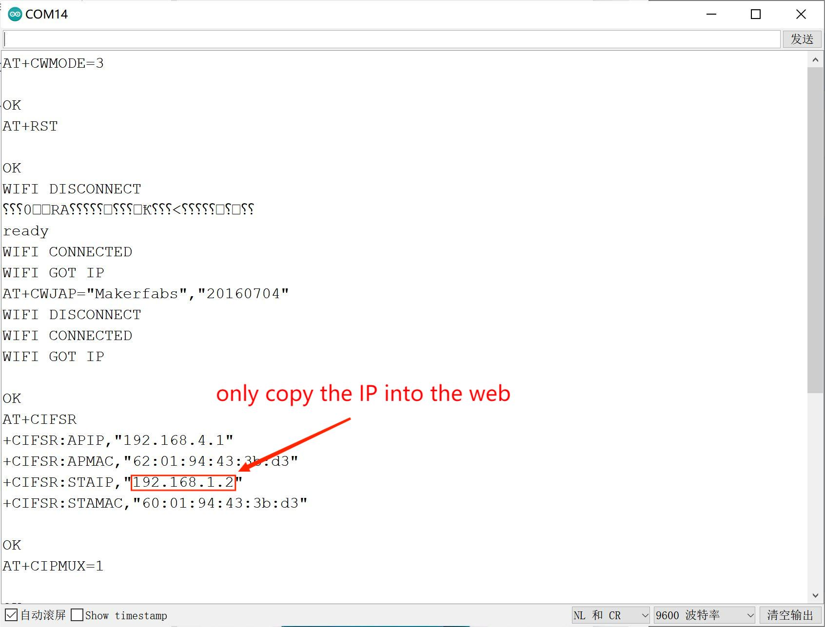
- Modify the wifi information in the code.
sendData("AT+CWJAP=\"Makerfabs\",\"20160704\"\r\n",5000,DEBUG); //modify the"SSID","PASSWORD" ,and must belong to your WIFI Configuration.
- Upload the code.
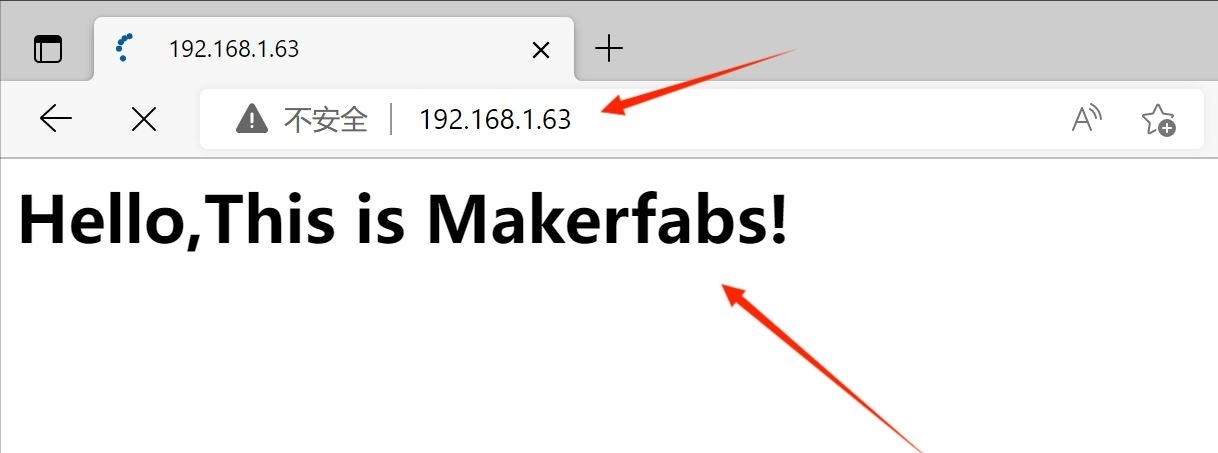
- Open the serial monitor to Check the wifi IP address.
- Open the browser and visit the IP address. if you receive the "Hello, this is Makerfabs!", the wifi test is successful.
IoT Project
A Simple IoT Project-Environment Remote Monitor
WiFi shield as an IoT WiFi module, its design of that base on esp8266 low power WiFi serial port communication. With the board, we can use it to remote control a lot of IoT projects or smart home projects. In this project, we will detect the humidity/temperature of our soldering lab, and reports it to internet thingspeak(https://thingspeak.com/channels/1840389), so we can monitor the lab/home/office/farm environment remotely.
We use the humidity /temperature sensor at: https://www.makerfabs.com/dht11-temperature-humidity-module.html
1.Sensor Connection
Connect the simple sensor to WiFi shield boards as follows:
| sensor | WiFi shield pins |
|---|---|
| Sensor's DATA | WiFi shield's D2 |
| Sensor's VCC | WiFi shield's 5V |
| Sensor's GND | WiFi shield's GND |
2.Programming
① Sign up for an account in https://thingspeak.com. If you ever registered the account. please Log in to it.

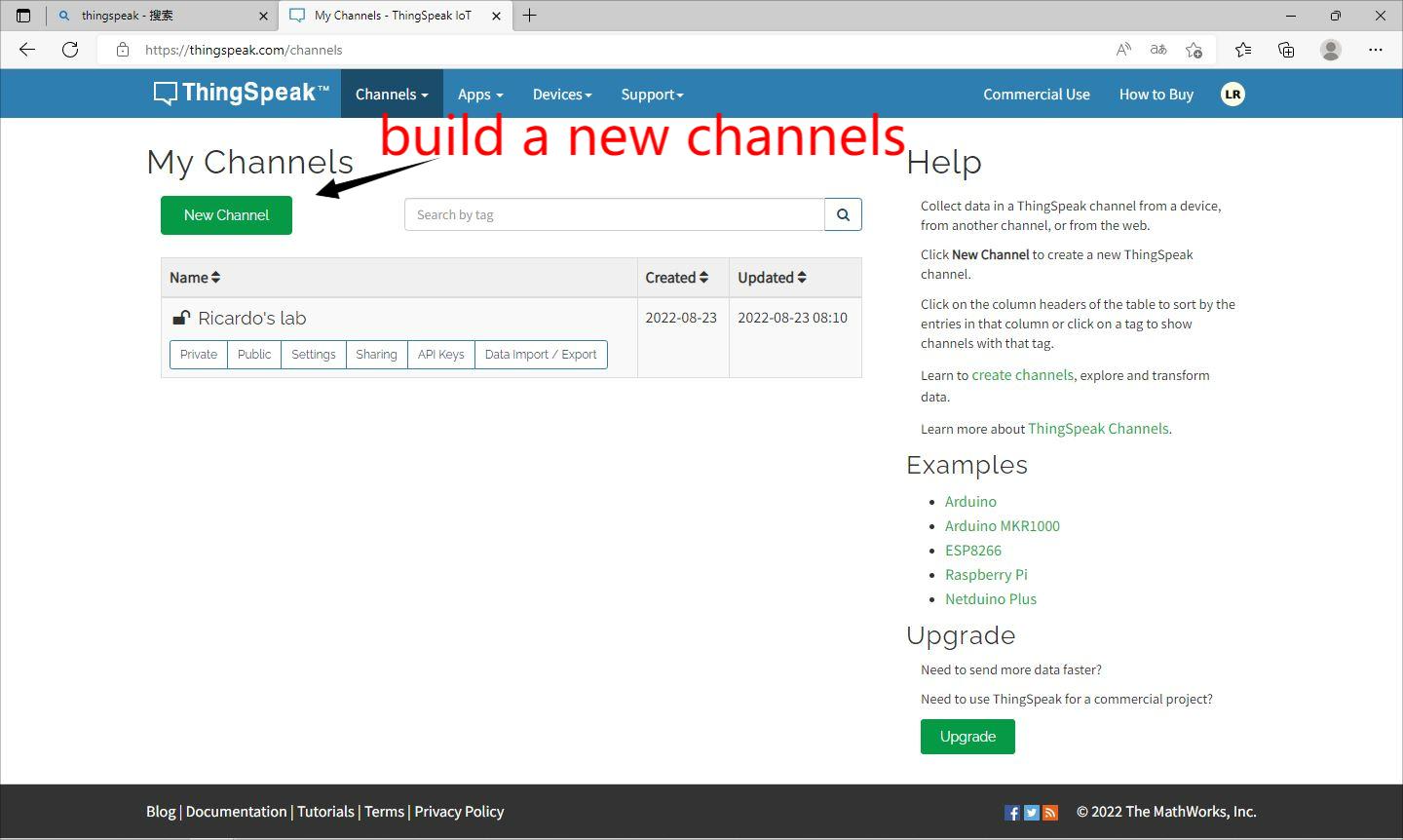
②Building a new channel belongs to you in the ThingSpeak.
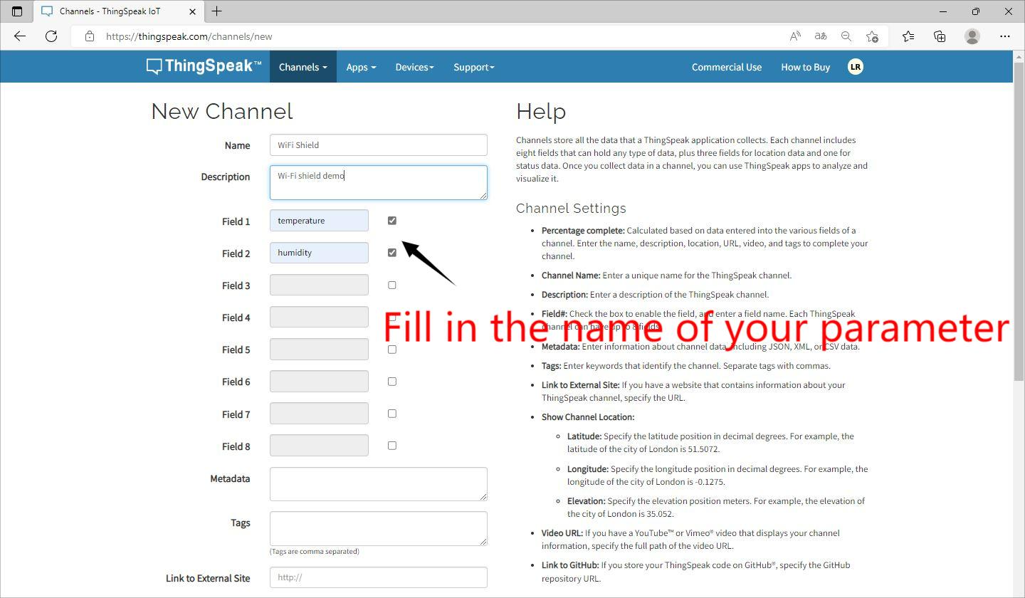
Configure your channel parameters.
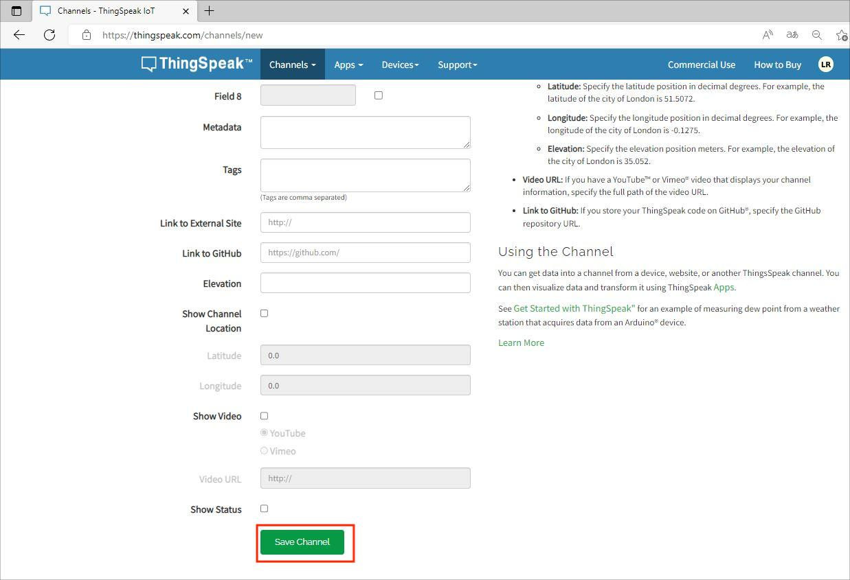
Then save the channel on the bottom.
③ Copy your API Key, we will instead it in the code WiFi Shield_DHT_HTTP.ino
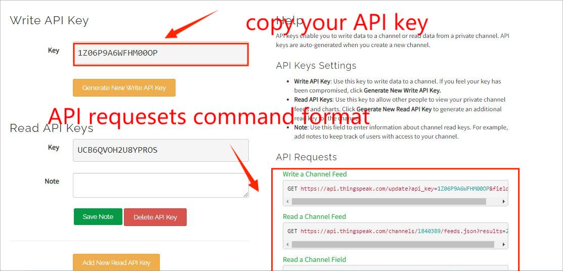
API key is the only certificate for you to visit your channel.
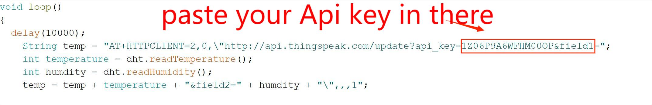
Because we mean to update the data of DHT11 in the thingspeak, so we use the format about Write a Channel Feed.
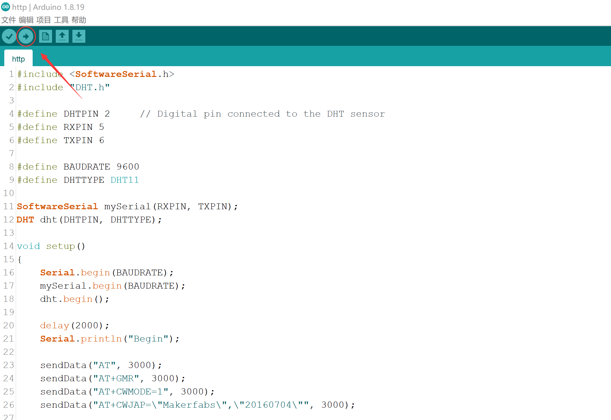
Select the right port and Arduino board:Arduino Uno and upload the code to WiFi Shield board. Upload the sketch.
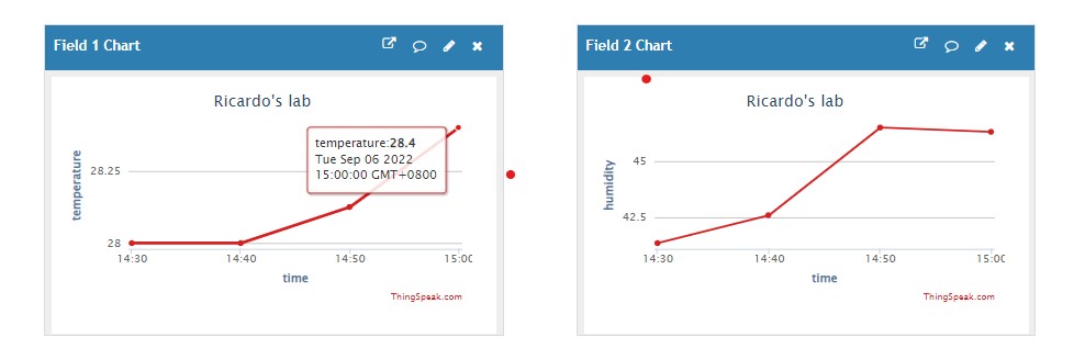
If the project could running successfully, surf in thingspeak web, refresh your channel and you will find that the sensor is successful update the data.
MQTT Project
A Project Of Light On Diode By Means Of Remote Control.
MQTT is a message publishing/subscription translation protocol basis for Client-Web. MQTT protocol is lightweight, simple, open, and easy to implement. These features make it a wide range of use. The best advantage of MQTT, which is use of few codes and limited bandwidth to provide real-time and reliable New service for linking remote devices. As an Instant Messaging protocol that has low overhead, low bandwidth utilization, which makes it has broader applications in IoT, small devices, and mobile applications, and so on. most importantly, MQTT can Now we can proceed with a simply MQTT application by using our WiFi Shield.
In the WAN, we can use MQTT to remote control something, like the status of the sensor or switch. So what we will show below is how to remote control to turn on and off the Diode using MQTT.
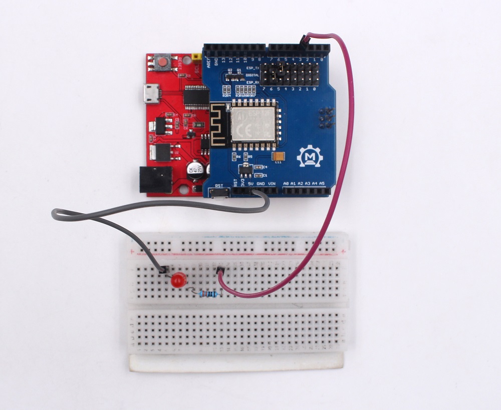
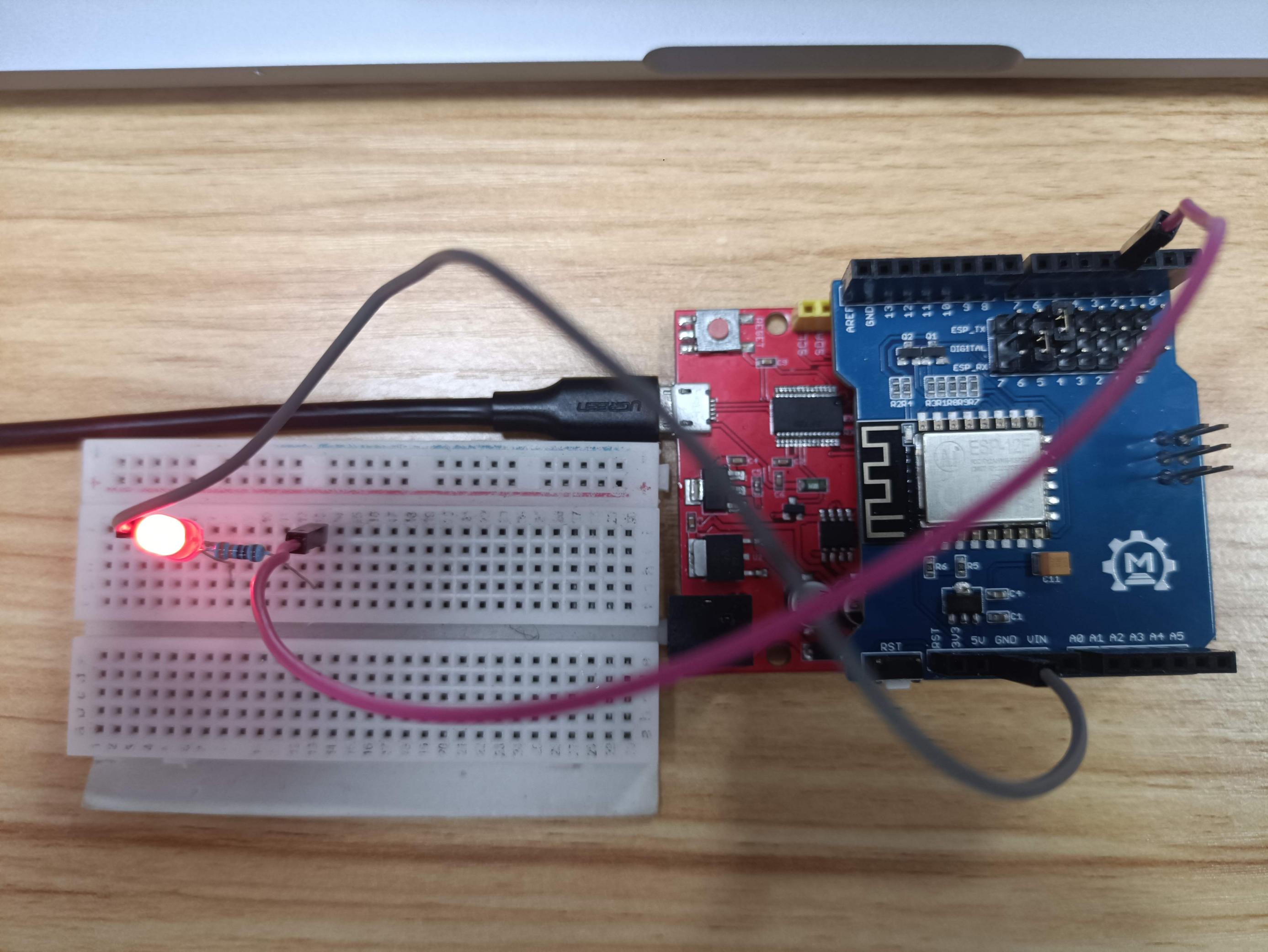
1.Hardware connection
The Hardware Schematic connection as follows NOTE: Please pay attention to the positive and negative terminals of a luminous diode, In the figure below, The left side of the LED is positive.
2.Programming
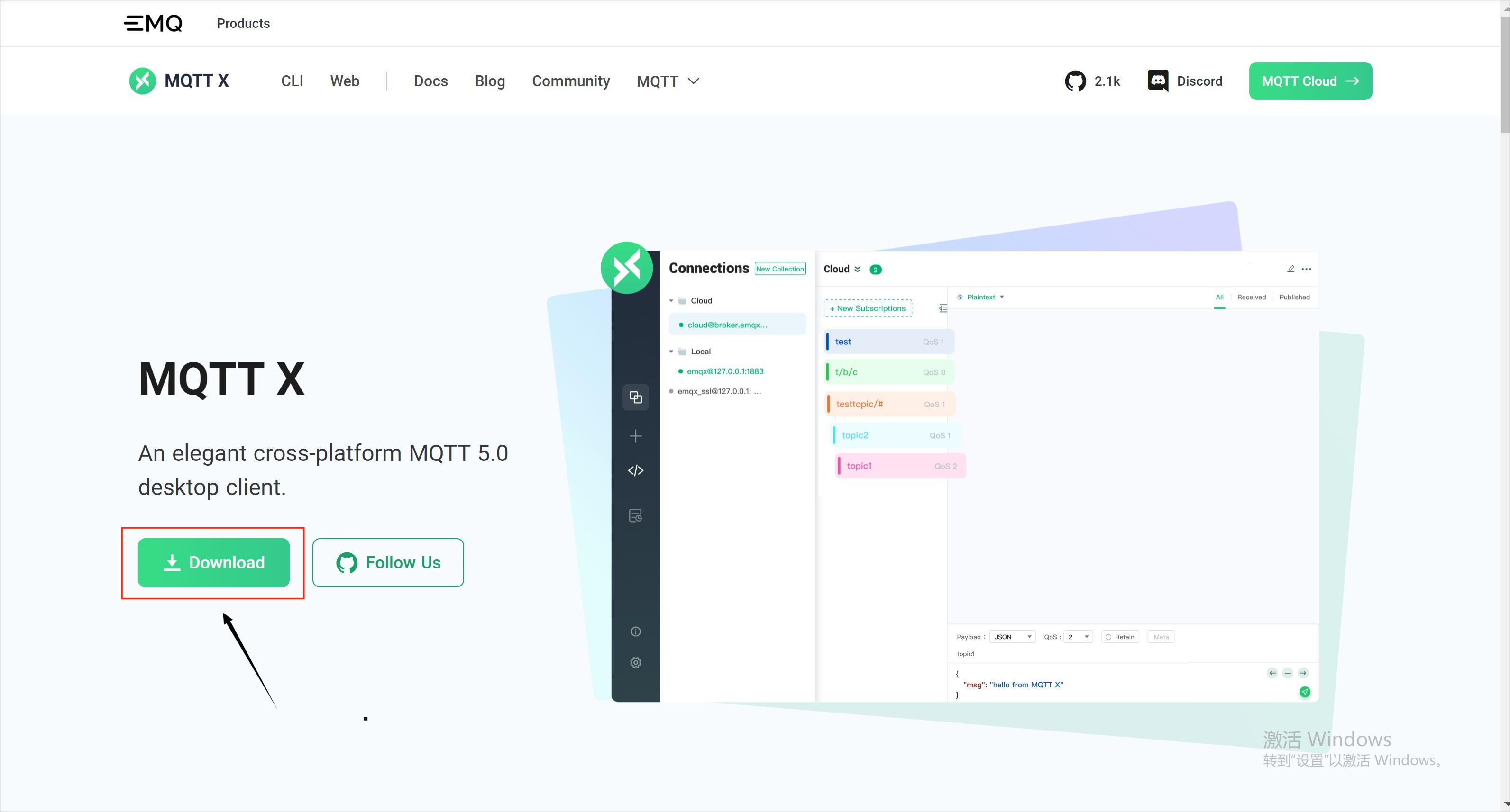
Download the software name “MQTTX”, install and configure it.
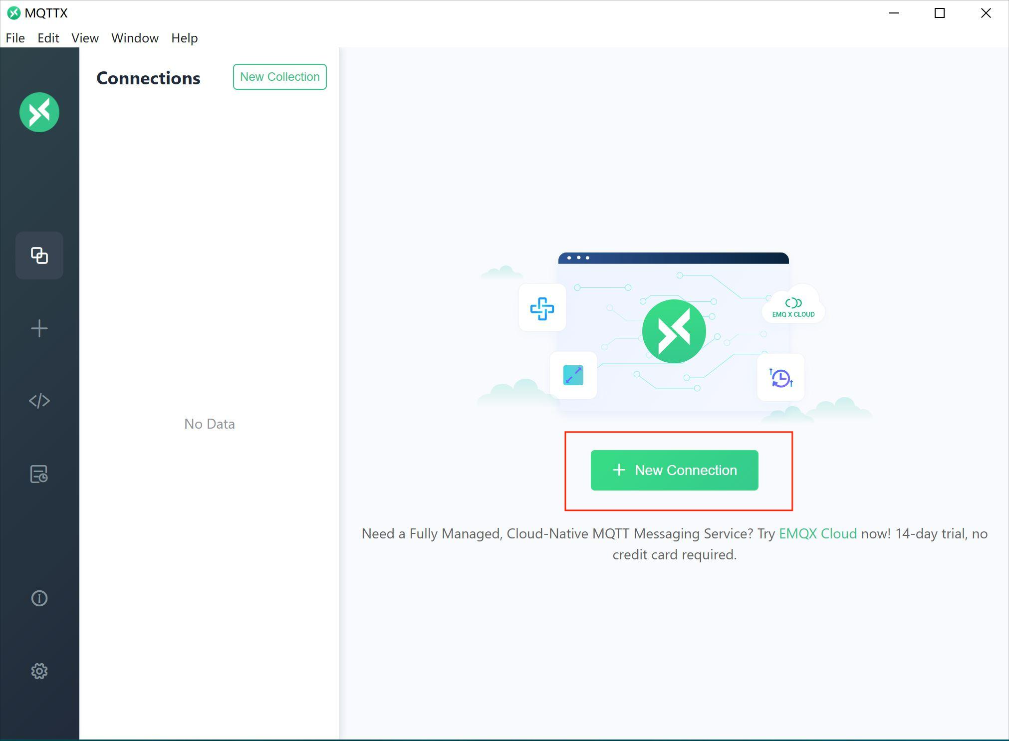
Create a connection and configure it as follow.
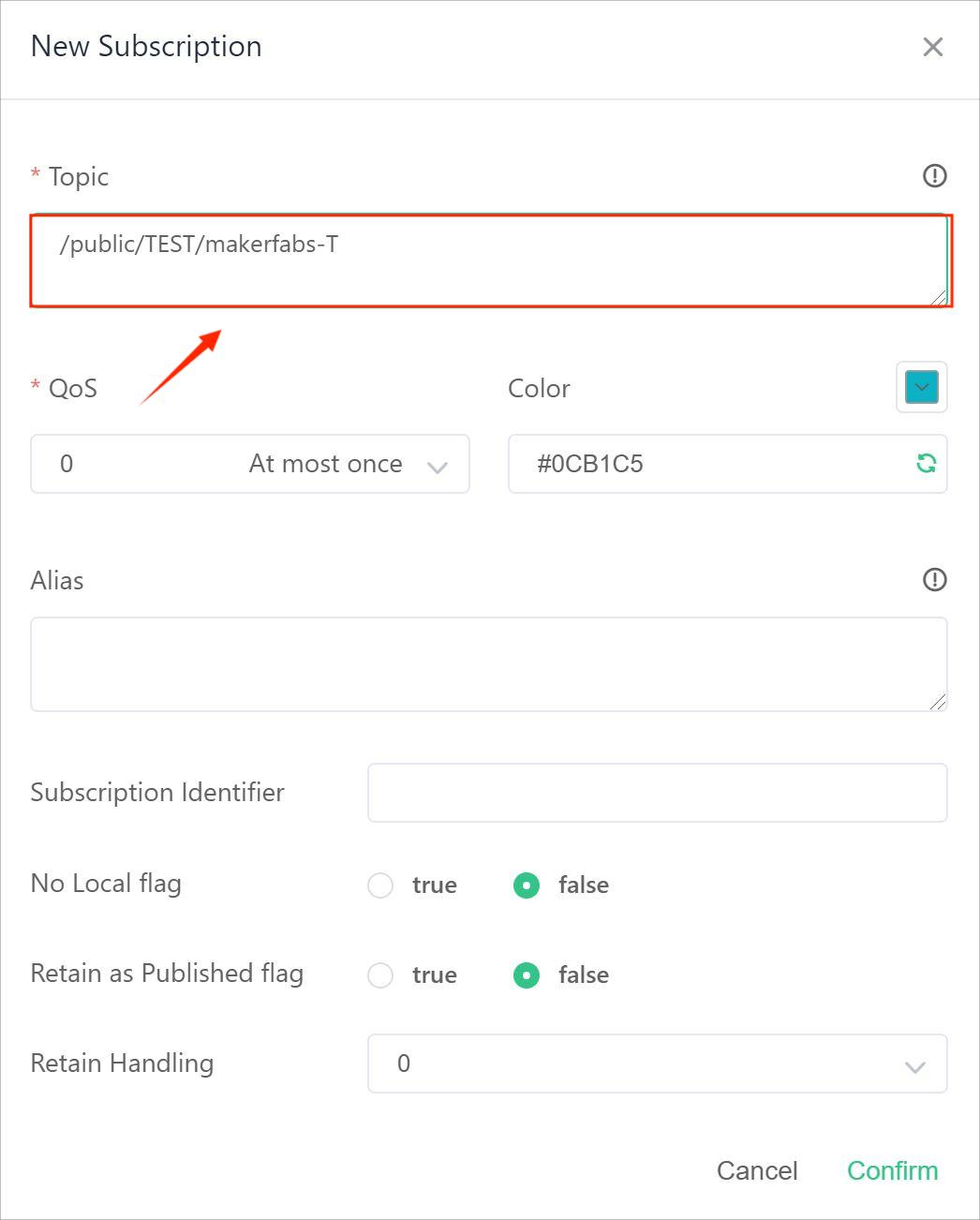
Copy the “MQTT_TOPIC” in the following figure. it can set up a new subscription.
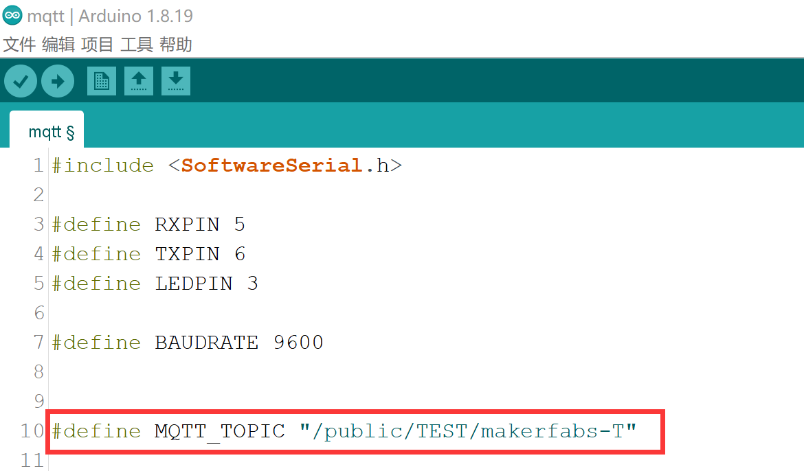
Set up the MQTT_TOPIC"/public/TEST/makerfabs-T"
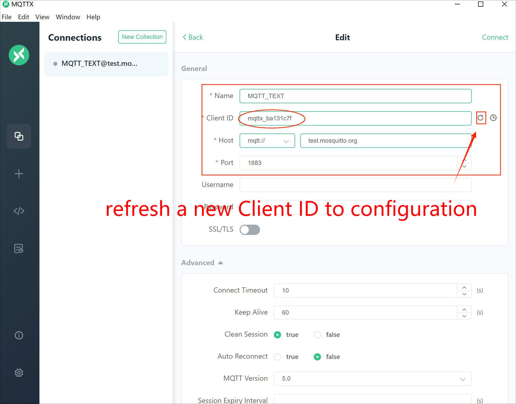
Sign in the “Name”,” Client ID”,” Host”,” Port”, and other configurations you just use the default setting.
Note: Two Client IDs must not be the same.
We know that publisher and subscriber have own unique Client ID, format like “mqttx_xxxxx”, therefore the publisher’s Client ID write in the code, and the subscriber’s Client ID write in the MQTTX application. The Client ID creates in MQTTX. You can copy a new Client ID to the code as a subscriber’s Client ID and refresh a new Client ID as a publisher’s Client ID.
Input the topic, which is "MQTT_TOPIC" in the code.

Select the right port and Arduino board: Arduino UNO and upload the code to WiFi Shield board. Upload the sketch.
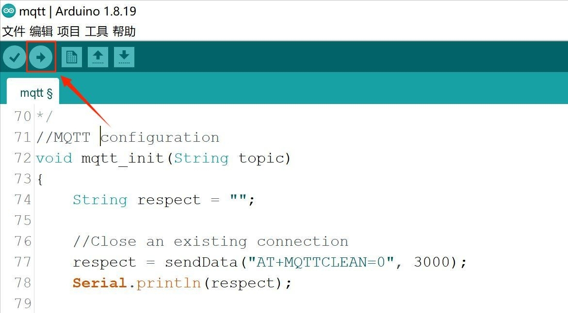
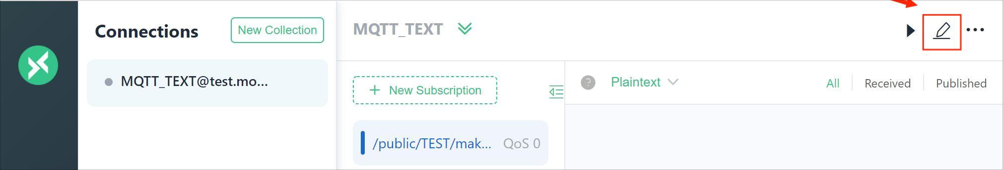
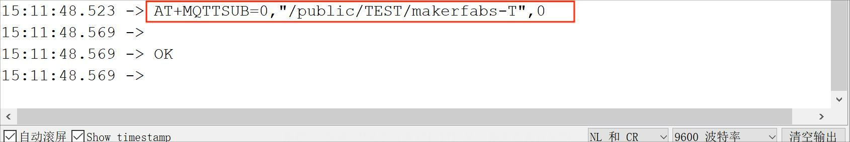
It means that you are successful with subscription.
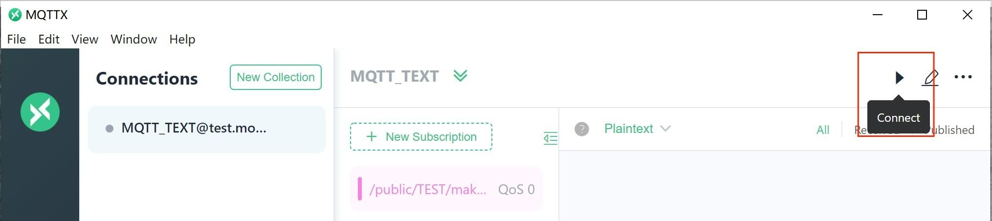
Connect to MQTTX, you can publish your massage now.
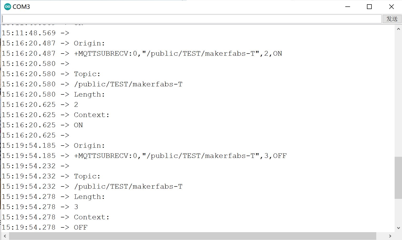
By the means of writing in the command at the client, you can turn on or turn off the luminous diode.
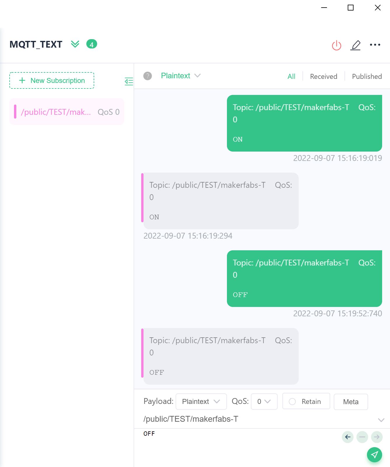
Also, We can see the serial monitor shows the log when operating.
If you want to learn more usage about the MQTTX, please click on https://mqttx.app/docs.
FAQ
You can list your question here or contact support@makerfabs.com for technology support.