Maduino Power-Line Communication
1. Introduction
Power-line communication (PLC) carries data on AC or DC wires. It works by adding a modulated carrier signal to the wiring system. the power distribution system was originally intended for the transmission of AC power at typical frequencies of 50 or 60 Hz, it has only a limited ability to carry higher frequencies, but for some applications such as the sensor monitoring in smart-home, that’s enough.
The Maduino Power-Line Communication(PLC) module has an onboard Atmega328p MCU for custom firmware development in the popular Arduino and Atmel Studio development environments; enabling one to create a custom smart home device and or powerline smart home network. For the power-line communication, it is based on the NXP TDA5051A modem which allows all three devices to communicate with one another when placed on the same power bus. The TDA5051 sends/receives data to/from the AC line and communicates with Atmega328P with standard serial communication(1200 band by default). This technology enables applications including but not limited to: lighting control, home appliance control, energy/heating control, and up to 3,000 feet data
Model:MAPLC
2. Features
- Atmega328P, compatible with Arduino
- USB-to-Serial: CP2104
- Modem IC TDA5051, full digital carrier generation, and shaping
- Communicates over 0 to +48VDC or 0 to 240VAC power buses
- Optically coupled zero-cross detection for system synchronization and or line freque- ncy measurements
- 1200bps baud data rate (default)
- power supply: 5VDC
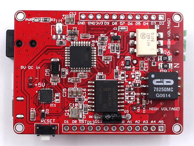
3. Hardware
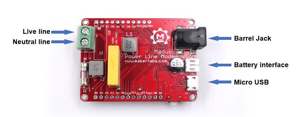
Interface
How it works
This module takes in a digital message from the MCUs UART bus and translates this digital message into an equivalent analog message. The circuitry on the board sends the analog message over the power line. The analog message will be broadcasted across the power lines that share the same circuit. Another board connected to the same circuit will hear this message.
4. Arduino Demo
Overview
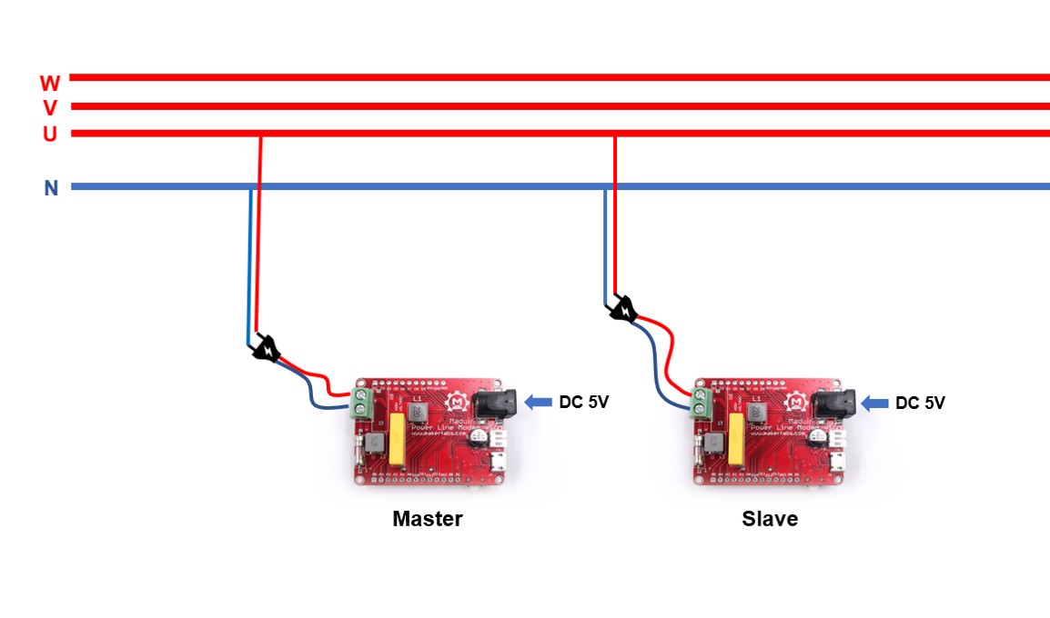
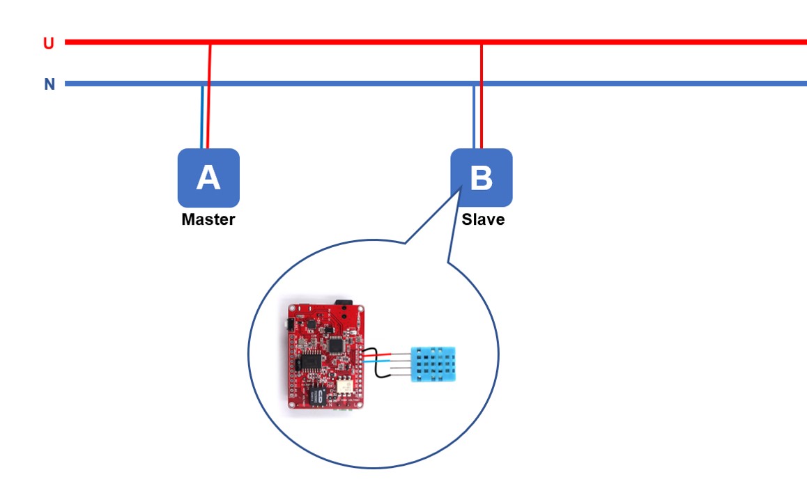
- Use two terminals (one is master and another is slave) to communicate with each other.
Preparation
- Prepare two Maduino Power Line Modem boards, that both are can be the master or slave to transmit and receive data. One of two also can be placed with other module supporting Power Line communication.
- Both are required to connect to the same phase of the power grid.
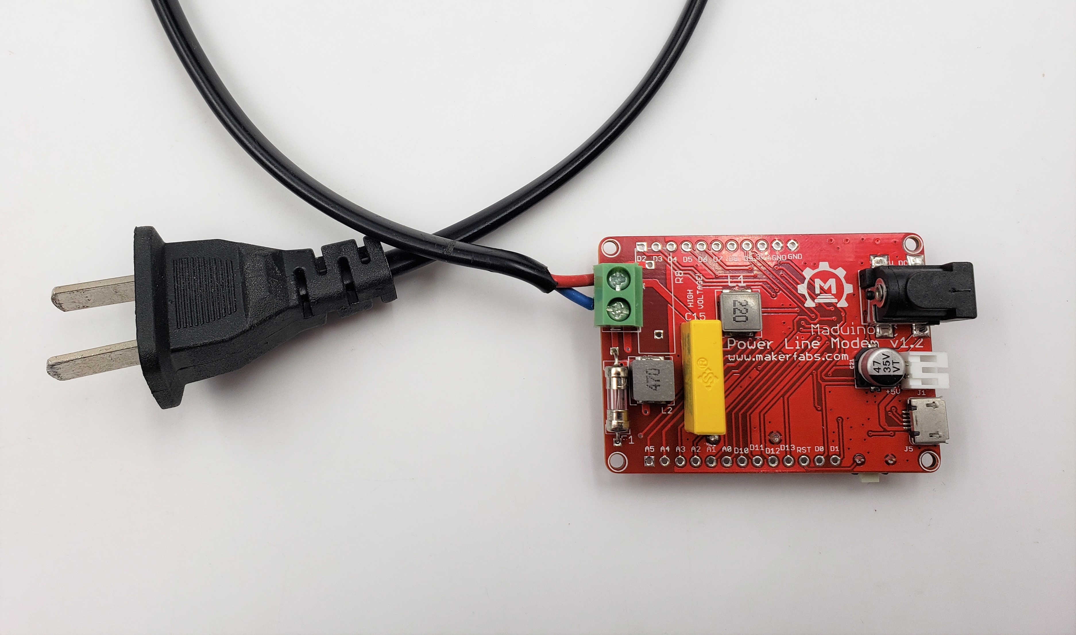
- To transmit or receive data from the electric power line, plug the Live Line and Neutral Line into the screw terminals.
- Except for connecting the power line, the boards still have to be powered by 5V with the DC-DC power jack or Micro USB cable.
Note: If you want to connect or disconnect the power lines, take care it and the power must be cut off first.
Demo code
- There are two kinds of code about master and slave that are available on GitHub.
- Upload the master code to the Maduino Power Line Modem board. 1.Connect the board to the PC by the USB cable.
2.Open the master code with Arduino IDE.
3.Select the correct development board (Arduino UNO) and port.
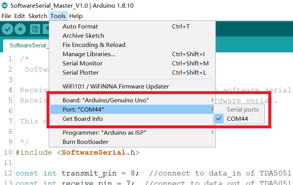
4.Verify and upload it to the board.
- Follow the above steps to upload the slave code to another board.
Result
- Plug the power lines into the screw terminal on board. Both boards must be connected to the power grid for the power line communication (Also can be connected to a network cable for testing).
- Power the slave by DC 5V
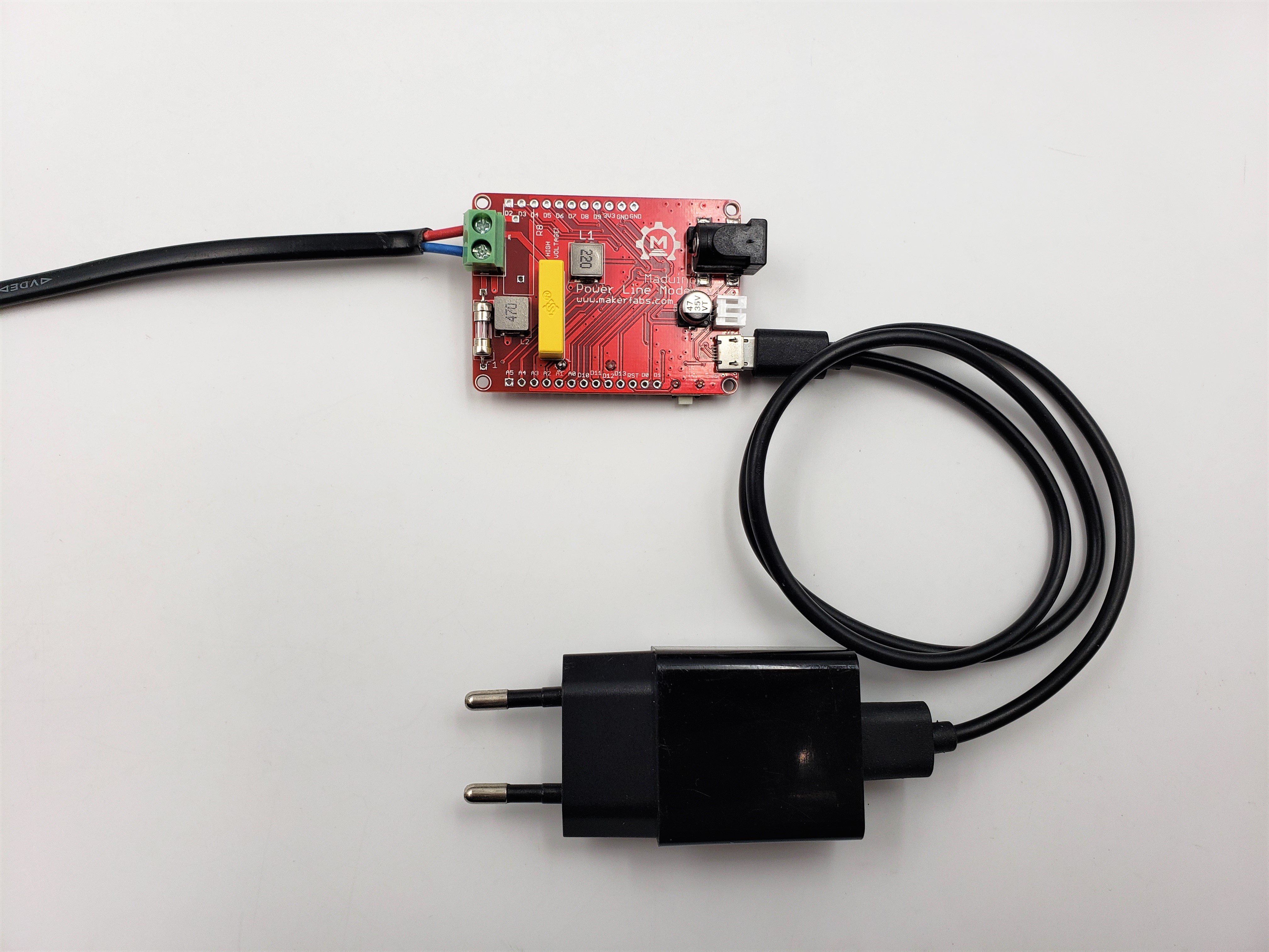
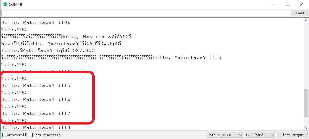
- Use a Micro USB cable to power the master board, and open the serial monitor of Arduino IDE to check the communication. If you will see the data slave transmitted show on the monitor, the communication is OK.
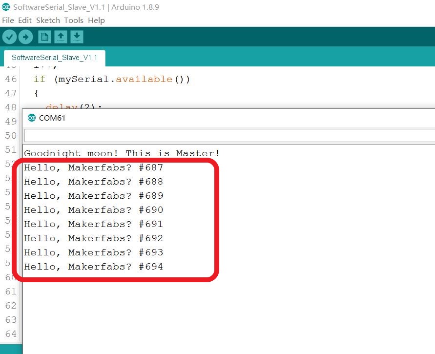
Checking
1.There are many factors affecting the transmission with the power line, that the slave will receive something except for the transmitted information.
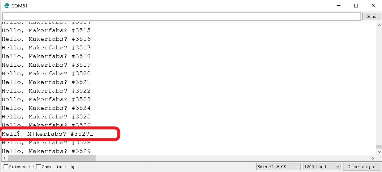
2.To filter the useless information, it has to add the checking bit on the transmission by programming. If a checking bit is detected, it is the information we need.
4.1 Transmit Temperature
Overview
For transmitting the temperature, connect the DHT11 sensor to the slave, and the master will receive the temperature reading over the power line.
- Upload the code(Transmitter_slave_DHT11)to the board, the code can be obtained from Github.
- Power it and go on the power line communication.
- The master will receive the temperature reading.
5. FAQ
You can list your question here or contact techsupport@makerfabs.com for technology support. Detailed descriptions of your question will be helped to solve your question.