MaTouch_1.9_inch_TFT_Breakout
1. Introduction
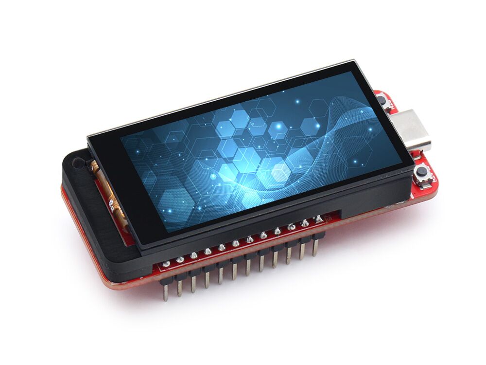
The Makerfabs MaTouch 1.9" board has garnered significant interest among users. However, based on feedback received, there was a consensus that the breakout of the ESP32S3 pins would enhance the usability of the board for various applications.
In response to user demands, the Makerfabs MaTouch 1.9" board brings creative updates. The enhancement lies in the breakout of all GPIO pins. Now, users can prototype their projects using a breadboard and integrate the board as a "controller" with other compatible devices. This optimization simplifies the development process and expand the board's utility.
Model:MA1989BRK
2. Features
- Controller: ESP32-S3
- Wireless: WiFi& Bluetooth 5.0
- LCD: 1.9", 320x170 resolution, driver ST7789V2
- LCD interface: 8 bit 8080
- Touch Panel Driver: CST816D
- USB: USB Native, Type-C
- Power Supply: USB Type-C 5.0V(4.0V~5.25V); 3.7V Lipo battery
- Button: Flash button and reset button
- MicroSD: Yes
- Arduino support: Yes
- MicroPython support: Yes
- Operation temperature: -40℃ to +85℃
3. Usage in Arduino IDE
3.1 Software setup
For the best user experience, it's important to use the recommended version throughout your development process. All projects are based on the ESP32-S3 development board, guaranteeing higher compatibility and stability. If you haven't installed the ESP32 Board SDK yet, follow the steps in this guide to get started quickly .
For the ESP32-S3 Development board version, we recommend using versions that have been verified, such as 2.0.16, which is more stable, and less prone to errors.
1.Install the Touchlib library.
- Open the sketch>include library> ADD.ZIP library,choose the download path of TouchLib and unzip the library to the Arduino library file.
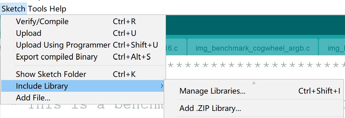
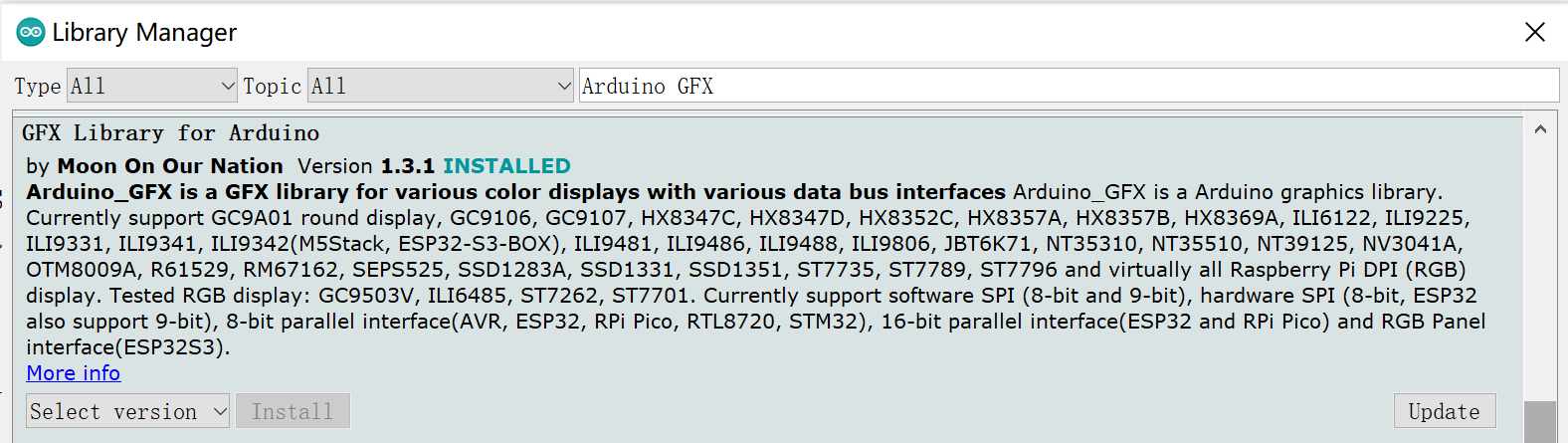
2.Install the GFX_Library_for_Arduino v1.3.1.
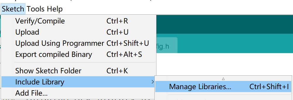
- Open the sketch>include library> Manage Libraries, install the GFX_Library_for_Arduino library.
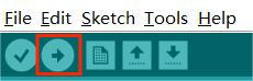
- Before uploading the sketch, select and set the parameter in the Tools menu, as show in image:
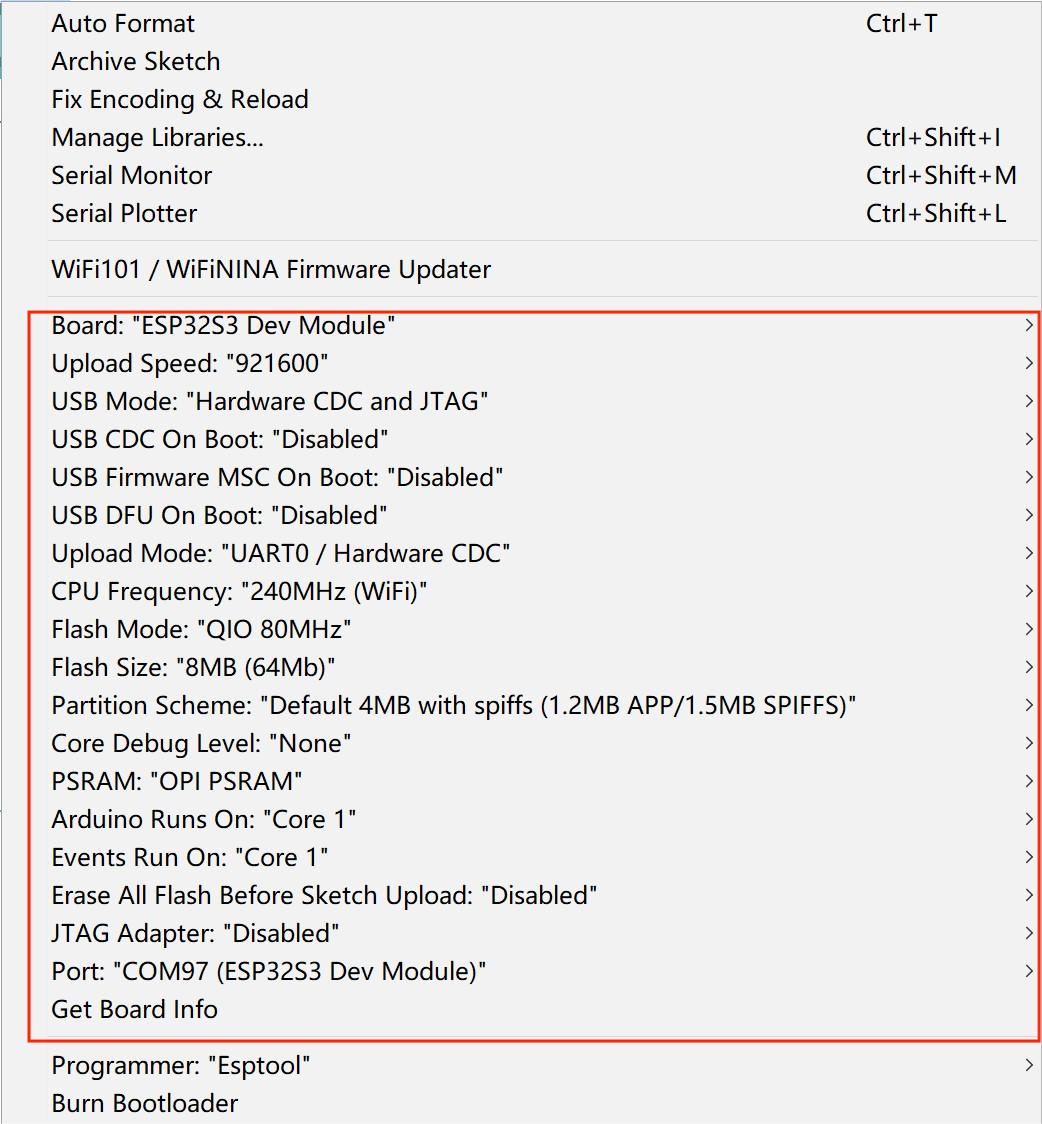
Note: Different computers may have different port numbers when connecting to a development board. Please select the correct port number based on the development board you are connecting to.
3.2 Firmware
This demo can test the touch with the screen.
1.Open the firmware by Arduino IDE.
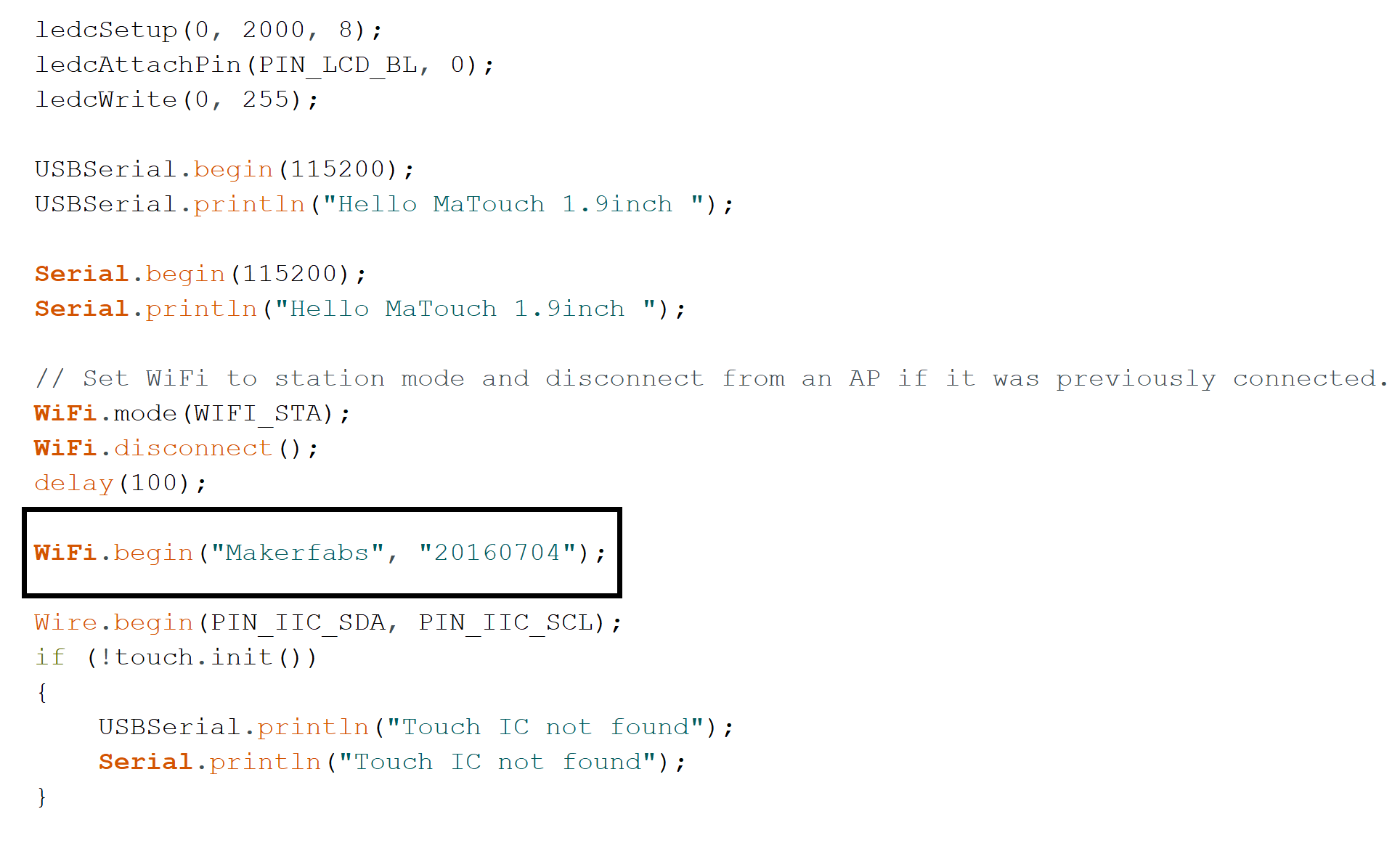
2.Insert your network credentials in the following variables.
3.Verify and upload the sketch.
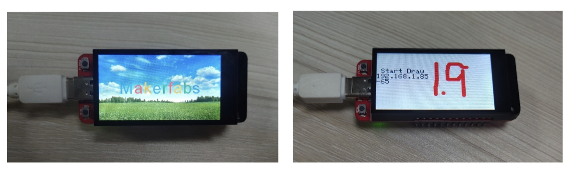
4.After uploading, the screen will be displayed as follows.
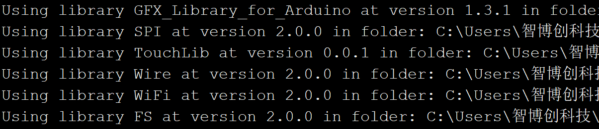
5.The version of the libraries shows as below. It may cause compilation errors if you use different version of the libraries!
3.2 Squareline_demo
Wire the DHT11 sensor, button and led to the MaTouch_1.9_inch_TFT_Breakout ,and the product can interact with them by downloading the example.
Before verifing and uploading the sketch, please install the same libraries in the Arduino IDE.
1.Install the Mf_Lvgl library.
-
Open the sketch>include library> ADD.ZIP library
-
Choose the download path of MF_Lvgl and unzip the library to the Arduino library file.
-
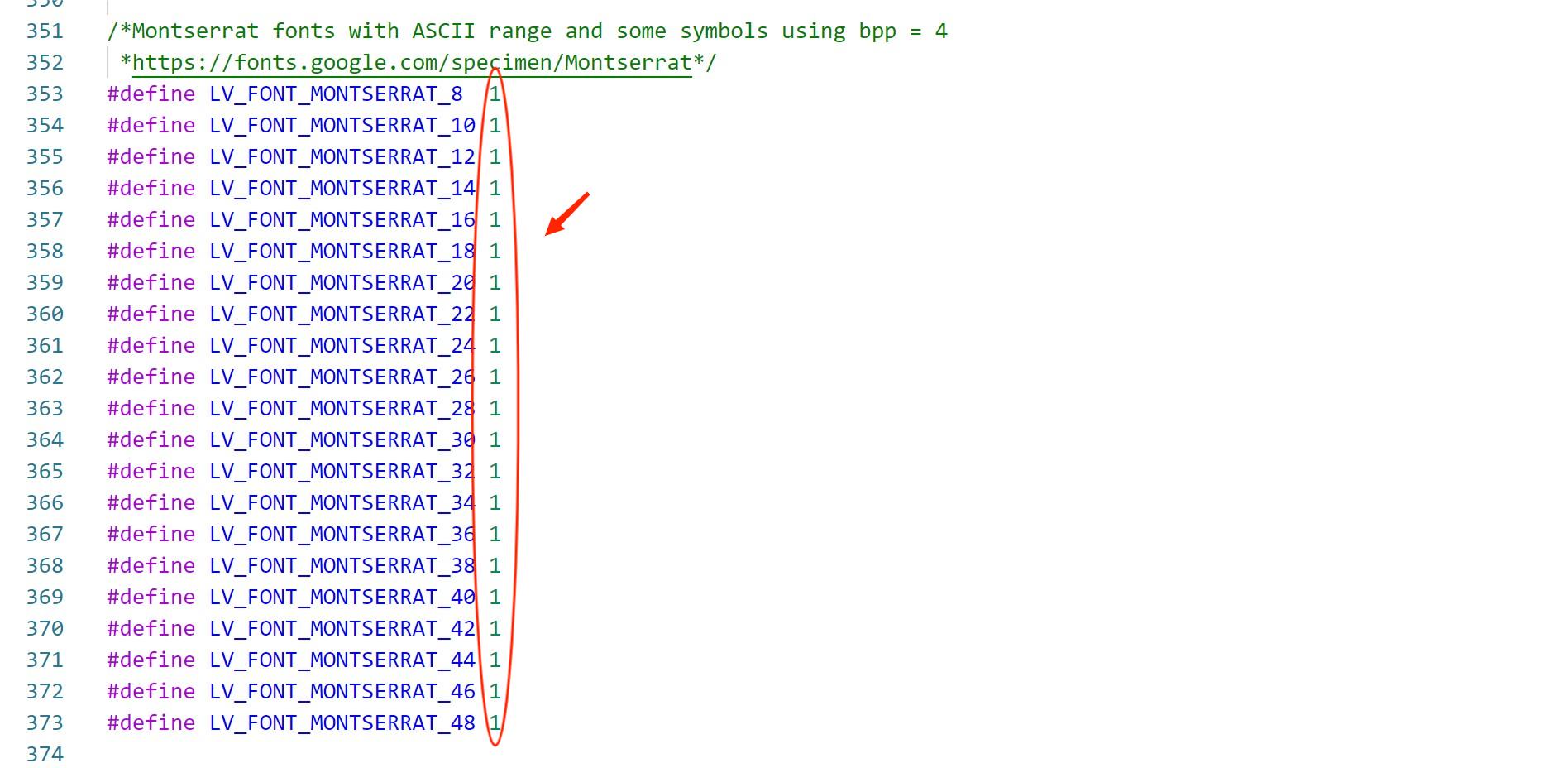
open the mf_lvgl>>src>>lv_conf.h, Modify the compile option to change 0 to 1, and save the configuration.
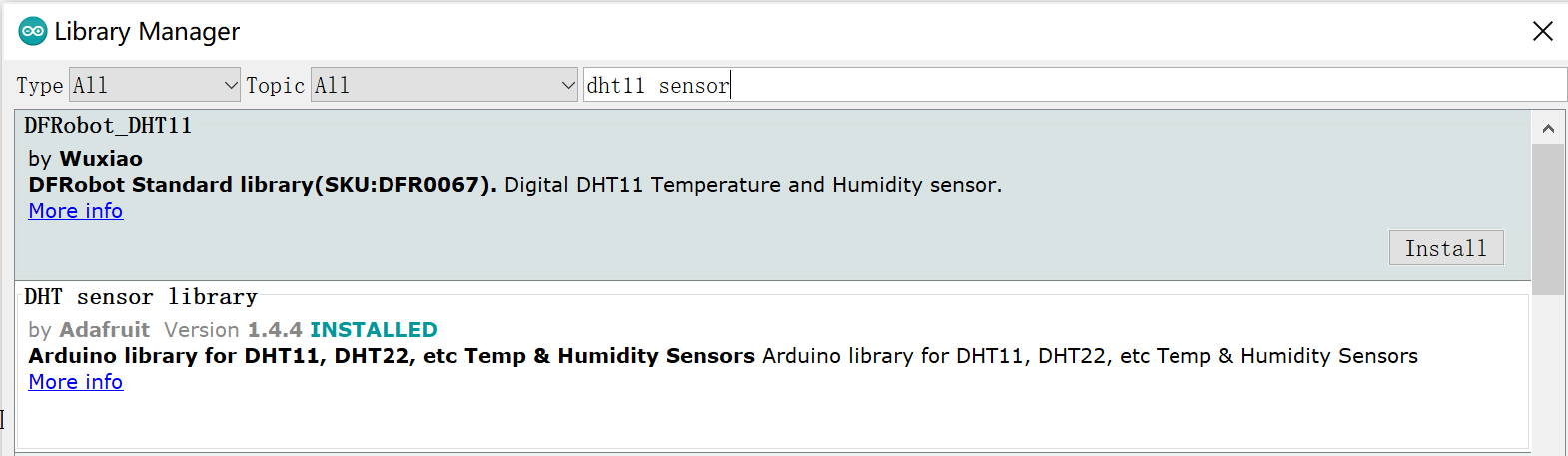
2.Install the DHT11_sensor_ library.
- Open the sketch>include library> Manage Libraries,choose the install DHT11_sensor_library.
3.Install the UI file.The UI file is designed to can be downloaded to the example in the form of arduino libraries.
-
Open the sketch>include library> ADD.ZIP library
-
Choose the download path of UI and install it to the Arduino library file.
4.Open the squareline_demo by Arduino IDE.
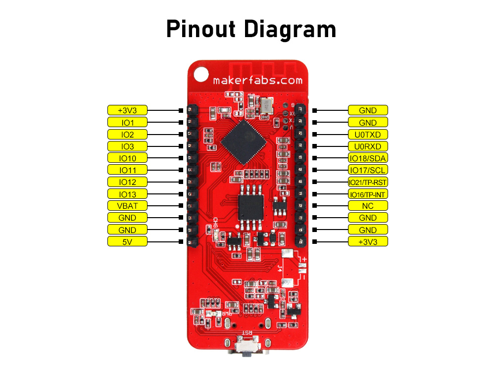
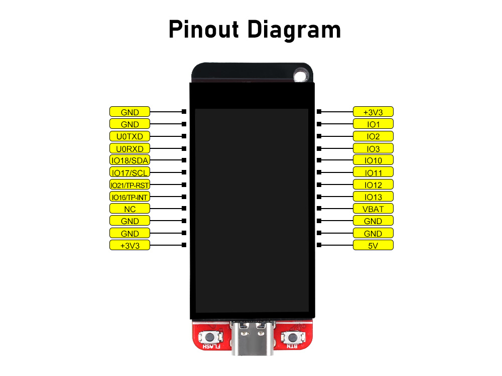
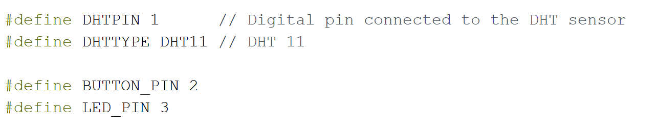
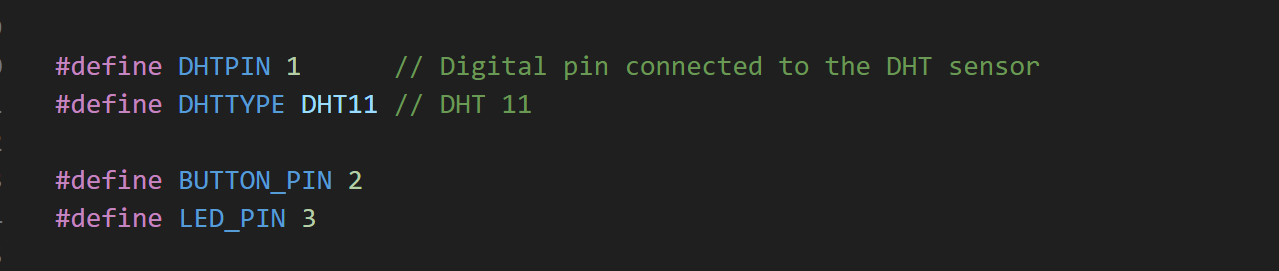
5.You can wire the hardware according to the pin definitions you are using, as show in image:
-
Connect the data pin of the DHT11 sensor to IO1.
-
Connect the INC pin of the button to IO2.
-
Connect the negative terminal of the LED to IO3.
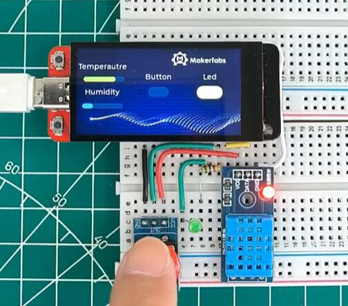
6.Verify and upload the sketch.
7.After uploading, the screen will be displayed as follows.
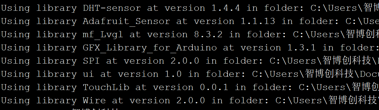
8.The version of the libraries shows as below. It may cause compilation errors if you use different version of the libraries!
4. Usage in VS Code & PlatformIO
Downloaded and installed PlatformIO IDE for VSCode
4.1 Firmware
This demo can test the touch with the screen.
Download and unzip the firmware, open this project by VS Code.
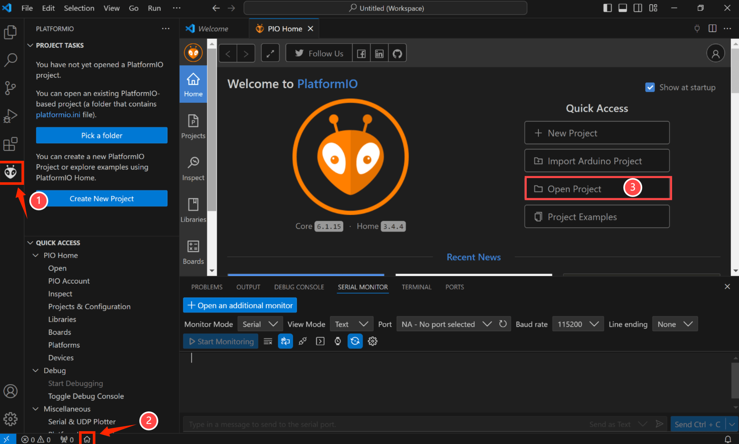
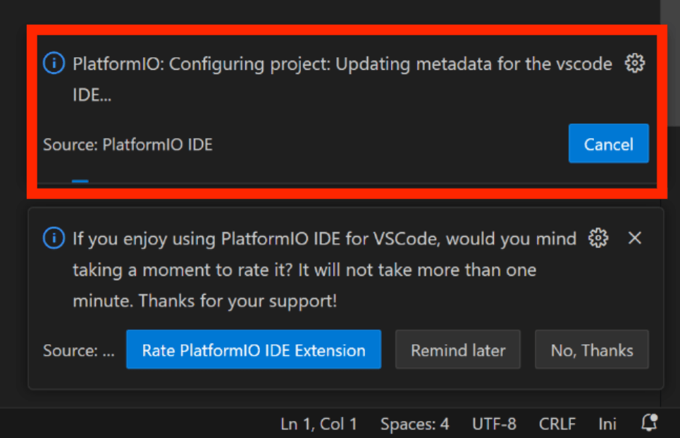
Waiting for configuration project.
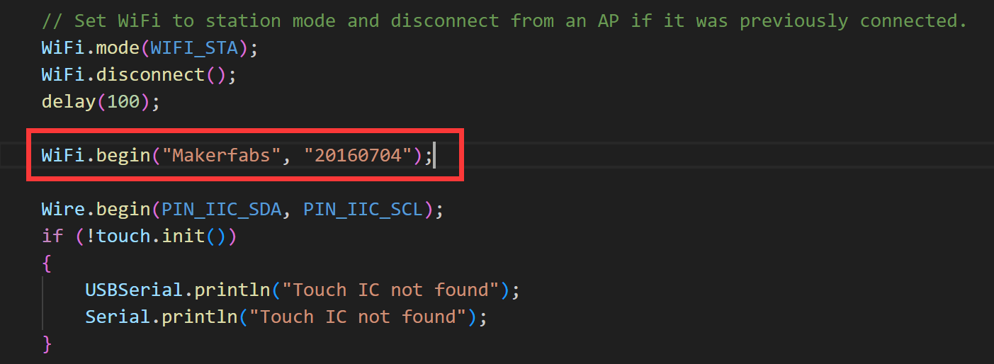
In the code, you must modify as your own WiFi-Configuration
- Click "src-->main.cpp".
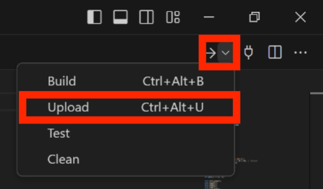
Verify it and upload.
Result:
4.2 Squareline_demo
Wire the DHT11 sensor, button and led to the MaTouch_1.9_inch_TFT_Breakout ,and the product can interact with them by downloading the example.
Download and unzip the squareline_demo, open this project by VS Code.
Waiting for configuration project.
Wire the hardware according to the pin definitions you are using, as show in image:
-
Connect the data pin of the DHT11 sensor to IO1.
-
Connect the INC pin of the button to IO2.
-
Connect the negative terminal of the LED to IO3.
Click "src-->main.cpp", verify it and upload.
Result:
5. Usage in Squareline Studio
For more the use of SquareLine you can refer to the video.
LVGL Usage with Squareline & MaTouch Lesson #1
LVGL Usage with Squareline & MaTouch Lesson #2
4. FAQ
You can list your question here or contact techsupport@makerfabs.com for technology support. Detailed descriptions of your question will be helped to solve your question.
-
Q: Why the display fails to respond sometimes I touch?
-
A: The touching interface is loose, please reconnect it.