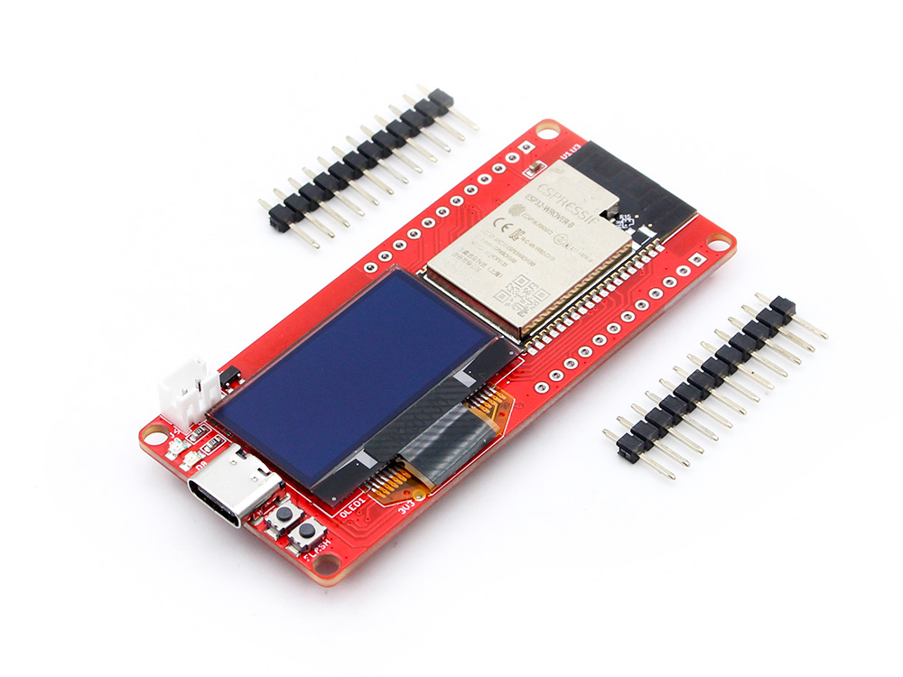
MaUWB_DW3000 with STM32 AT Command
Introduction
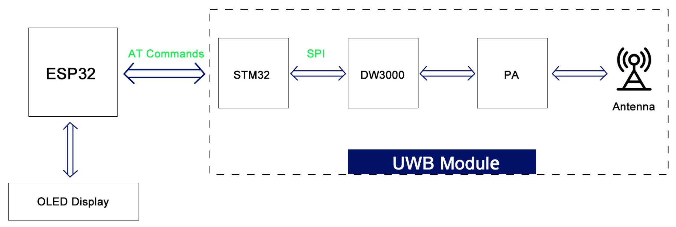
This module integrates MCU and all RF circuits, antennas, power management and clock circuits. The module can be quickly configured and used by AT command. The latest UWB module that solves multiple anchors& tags mutual conflicts, supports max 8 Anchors + 64 tags in application, to create a multi-anchor multi-tag positioning system, and supports antenna delay settings for tags and anchors
Model:MAUWBCA1
Features
- Comply with IEEE802.15.4-2011 ultra-wideband standard;
- Easy to integrate without additional RF design;
- Support CH5 (6489.6MHZ) RF band;
- Strong resistance to multi-path fading;
- Two modes of data transmission rate of 850kbps and 6.8Mbps;
- The maximum packet length is 1023 bytes, which meets the application requirements of high data volume exchange;
- The system supports 8 Anchors 64 tags.
- The module supports free configuration of refresh rate, up to 100Hz;
- Module serial port communication baud rate 115200;
- Module (Tag) deep hibernation working current as low as 35uA, working current 34mA;
- Support AT command;
- Board USB supply voltage range: 4.8~5.5V, 5.0V Typical
- Board Battery supply voltage range: 3.4~4.2V, 3.7V Typical
Arduino IDE preparations
-
Install the Arduino IDE V1.8.10/V1.8.19.
-
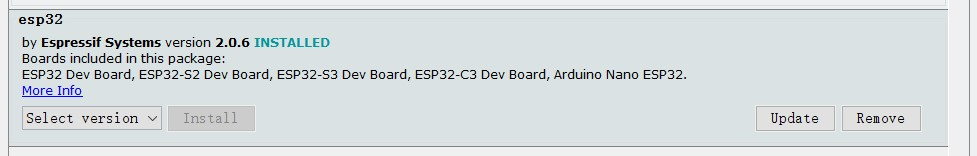
Install the ESP32 board package.
All projects are based on the ESP32-S3 development board, guaranteeing higher compatibility and stability.If you haven't installed the ESP32 Board SDK yet, follow the steps in this guide to get started quickly.
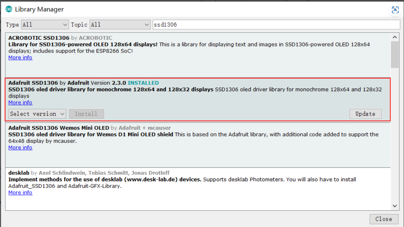
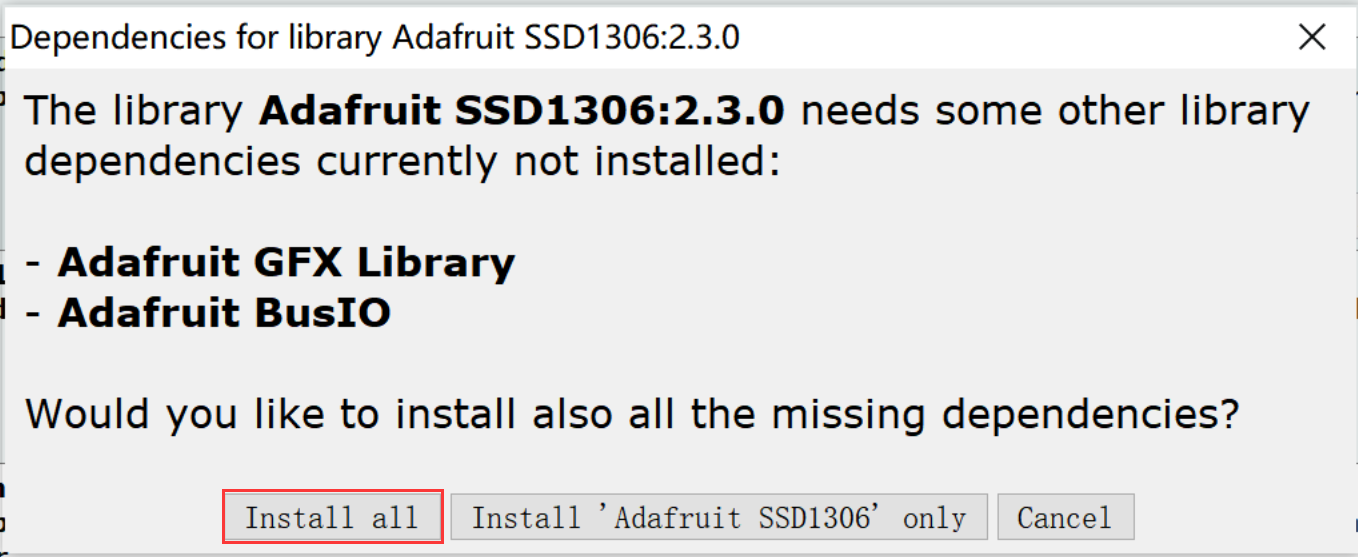
- Install "SSD1306" library(Version2.3.0)
Arduino has its own library manager, and for some authenticated third-party libraries, it can be searched in the library manager. Click install. Common libraries such as SSD1306.
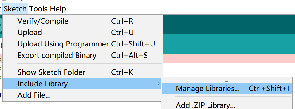
- Select "Sketch > Include Library > Manage Libraries", and search libraries that you need.
- If the following page appears, click"Install all"
Usage
The ESP32 controller can get the UWB arranging result simple by AT commands.
1. One Anchor + one Tag
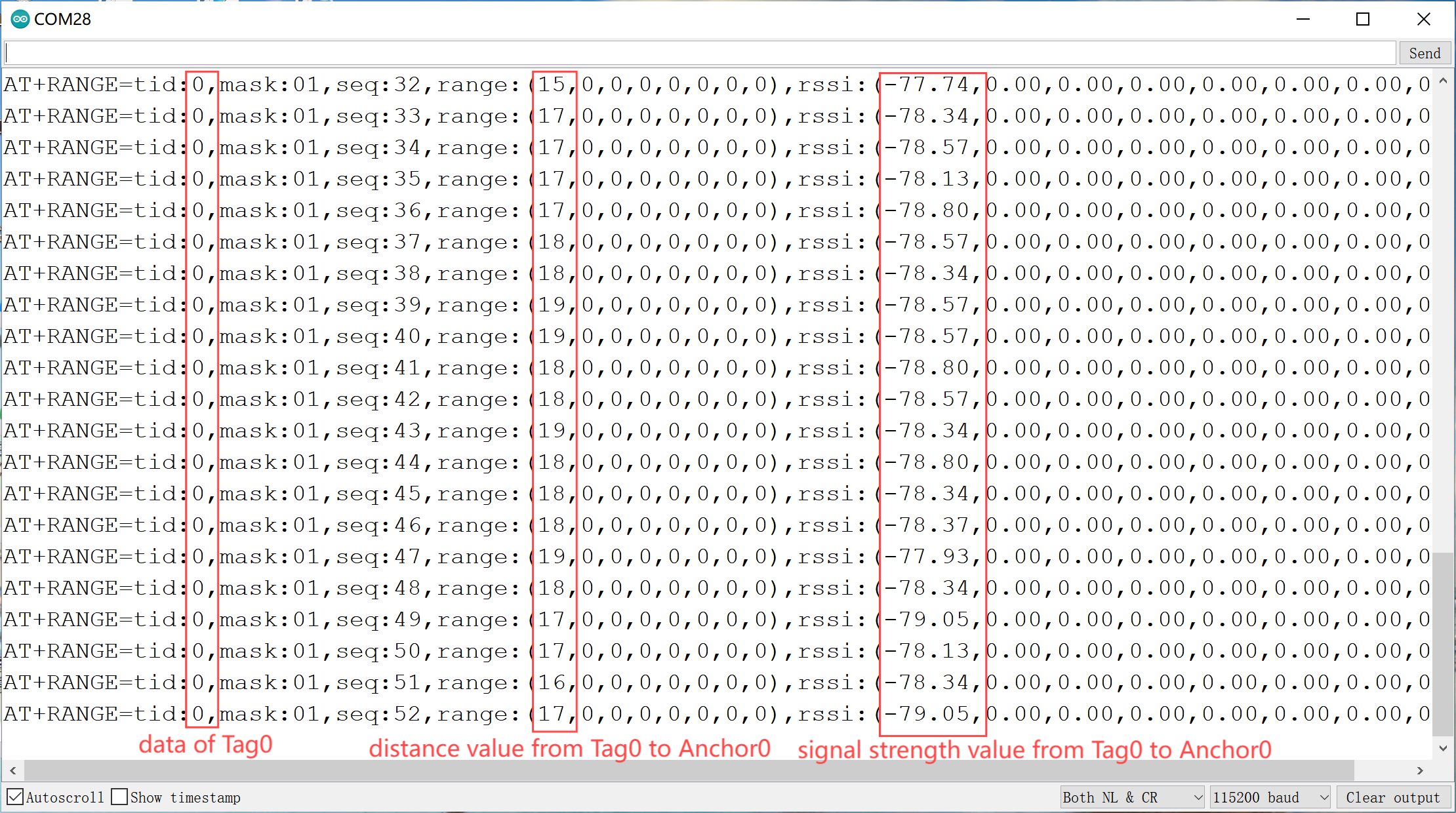
This is the example to get the distance and signal strength value from Tag0 to Anchor0.
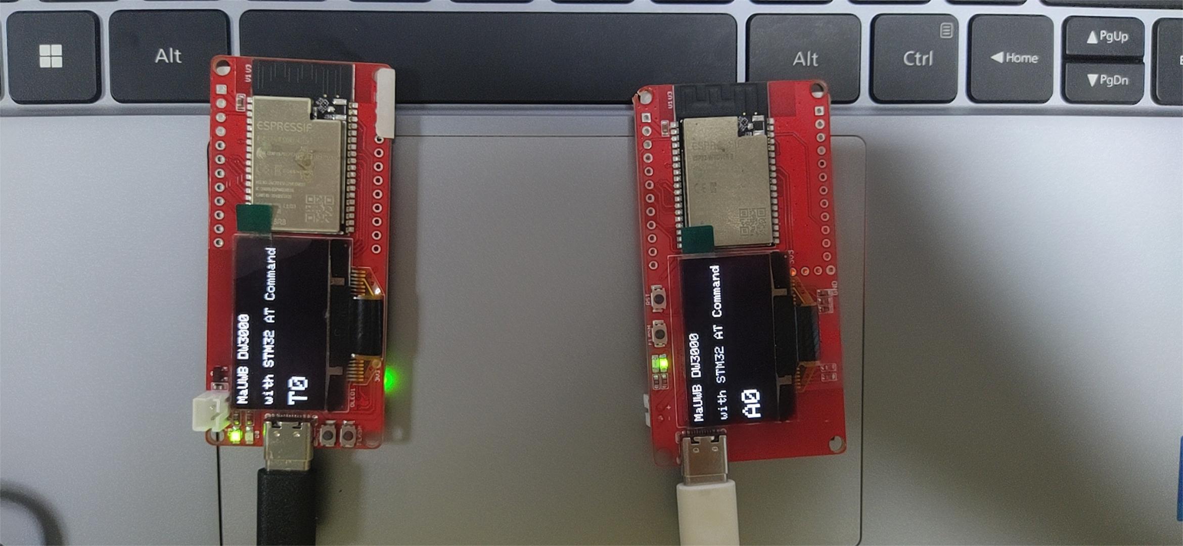
Set the board to Tag0
Open the Set to Tag0 by Arduino IDE.
Use Type-C USB cable to connect the board and PC, and select the development board "ESP32 Dev Module" and the port.
Verify the code and upload.
Set the board to Anchor0
Open the Set to Anchor0 by Arduino IDE.
Use Type-C USB cable to connect the another board and PC, and select the development board "ESP32 Dev Module" and the port.
Verify the code and upload.
When it is successful,open the Arduino IDE serial monitor, and you can see the distance and signal strength value from Tag0 to Anchor0.
Note AT command details please check Makerfabs_UWB_AT_Module_AT_Command_Manual(v1.0.8).pdf.
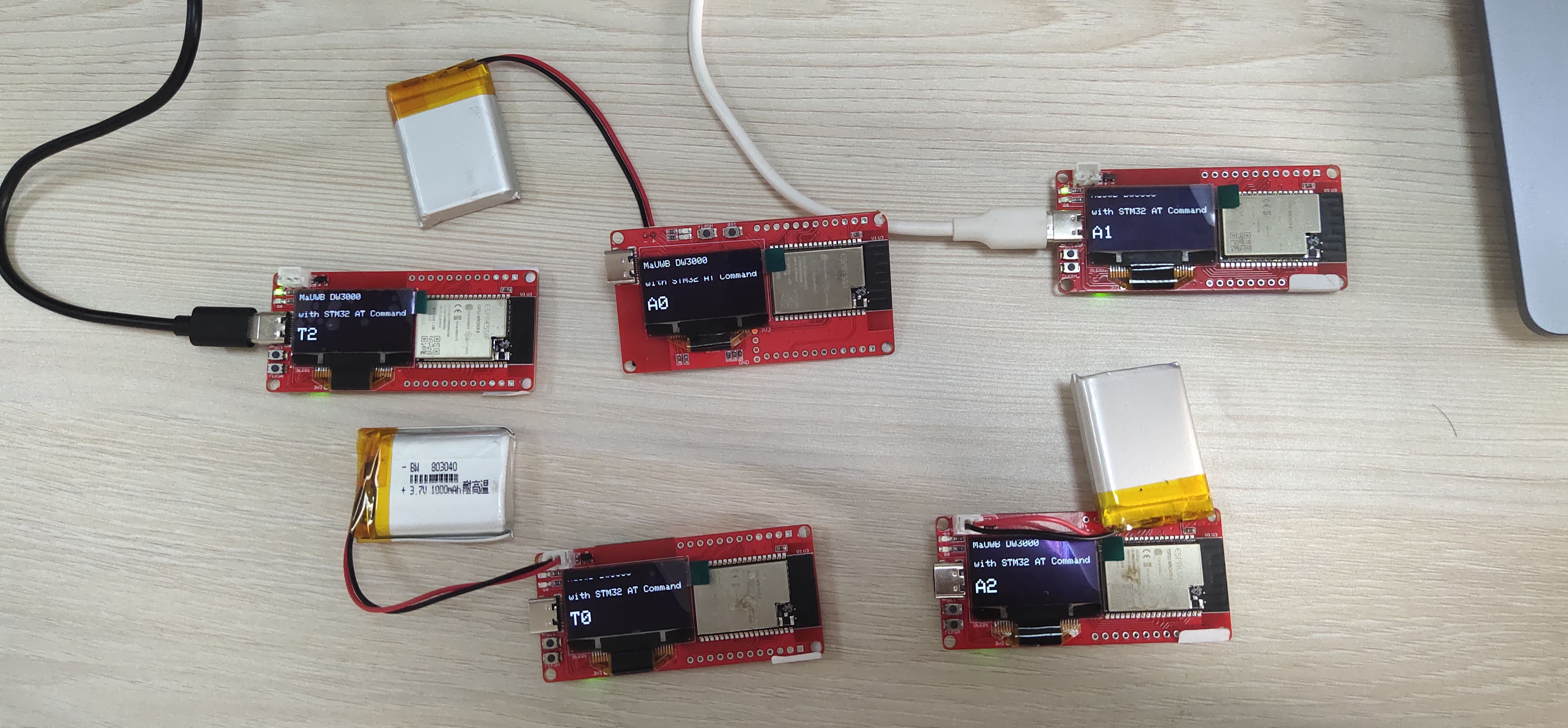
2. Multi Anchor + Multi Tag
This is the example to get the distance and signal strength value from multi Tag to multi Anchor.
Set the board to Anchor X or Tag X.
Open the Set to Tag0 by Arduino IDE.
Modify code to get the Anchor or Tag that you want to define.
sendData("AT+SETCFG=0,0,0,1", 2000, 1);
display.println(F("T0"));
You can set the basic module parameters using "AT+SETCFG=(x1),(x2),(x3),(x4)"
x1:Device ID(Anchor 0-7,Tag 0-31)
x2:Device Role(0:Tag / 1:Anchor)
x3:Equipment communication rate(0:850K/1:6.8M,Default:6.8M)
x4:Range filtering is enabled(0:Close / 1:Open)
Here are some examples.
//A0
AT+SETCFG=0,1,0,1

//A1
AT+SETCFG=1,1,0,1

//A2
AT+SETCFG=2,1,0,1

//A3
AT+SETCFG=3,1,0,1

//T0
AT+SETCFG=0,0,0,1

//T1
AT+SETCFG=1,0,0,1

//T2
AT+SETCFG=2,0,0,1

//T3
AT+SETCFG=3,0,0,1

//T4
AT+SETCFG=4,0,0,1

//T5
AT+SETCFG=5,0,0,1
Use Type-C USB cable to connect the board and PC, and select the development board "ESP32 Dev Module" and the port.
Verify the code and upload.
Repeat to set up multiple Anchor and multiple Tag.
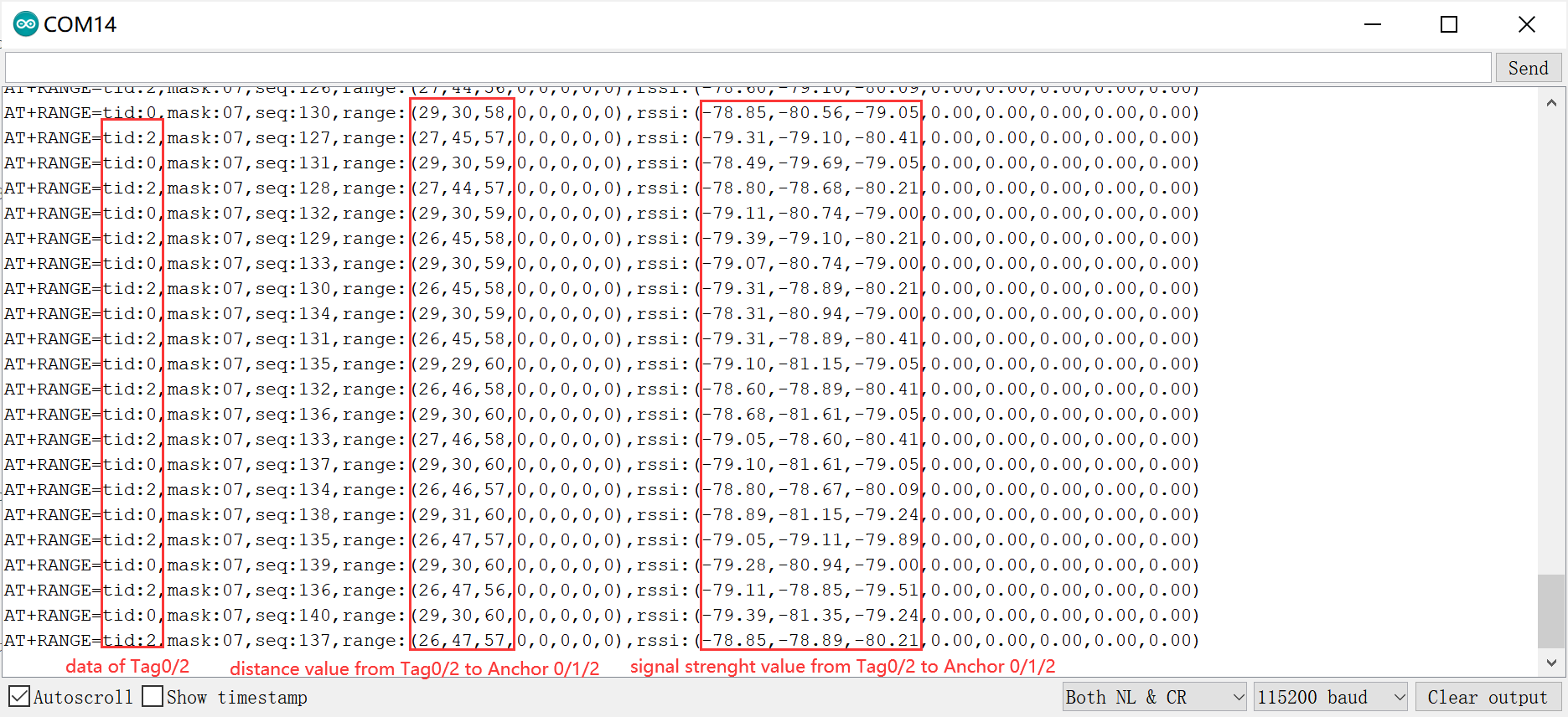
When it is successful,open the Arduino IDE serial monitor, and you can see the the distance and signal strength value from multi Tag to multi Anchor.
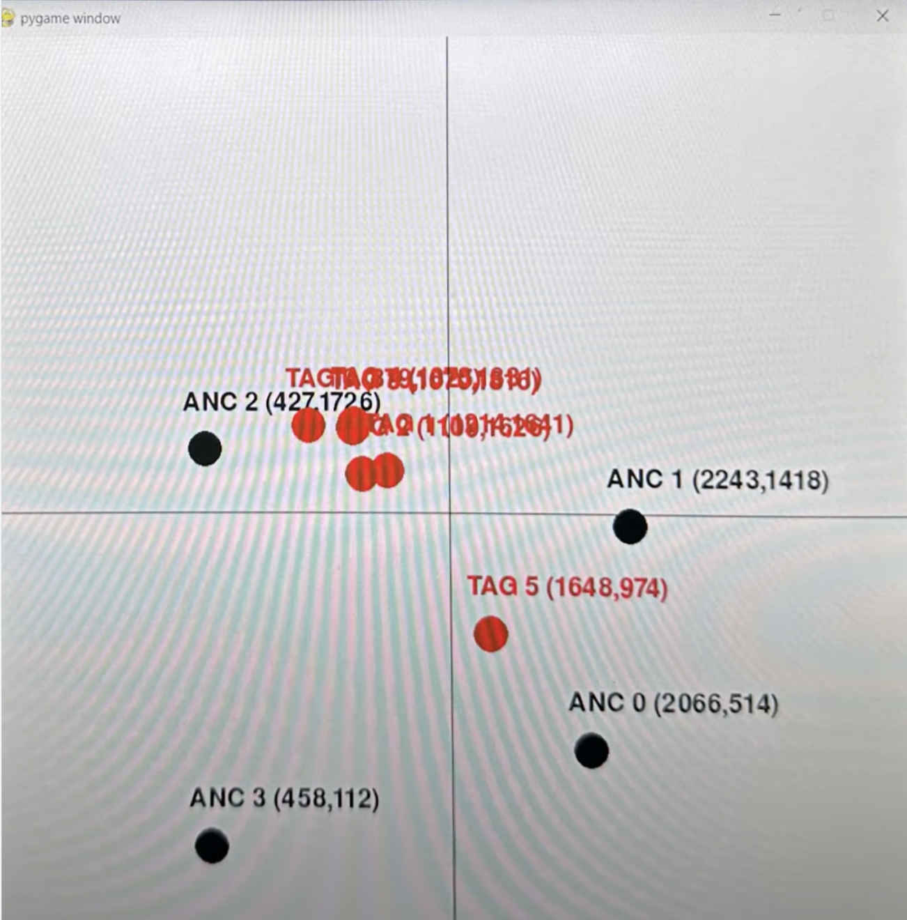
How to achieve four-point positioning, you can refer to this article.
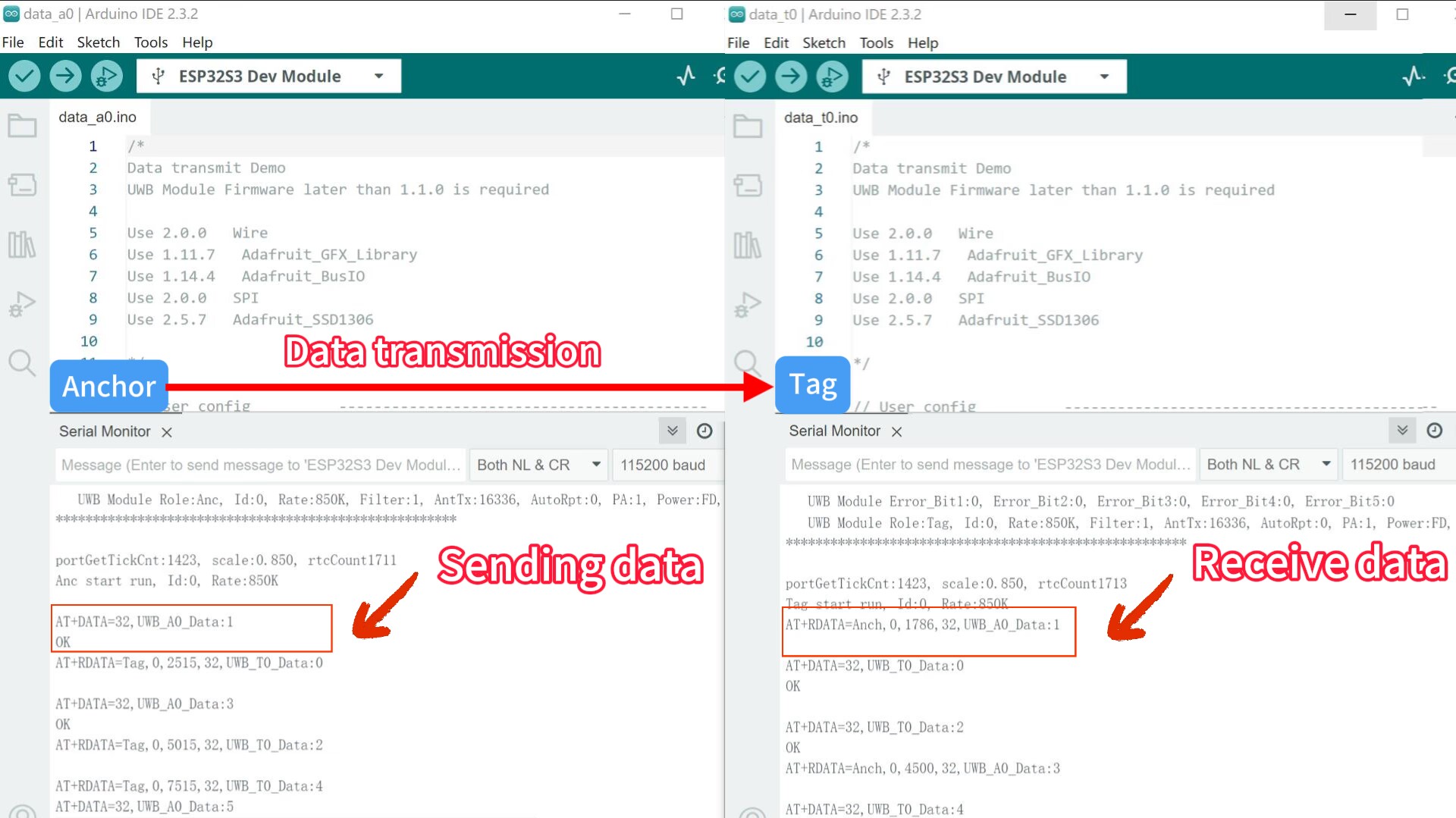
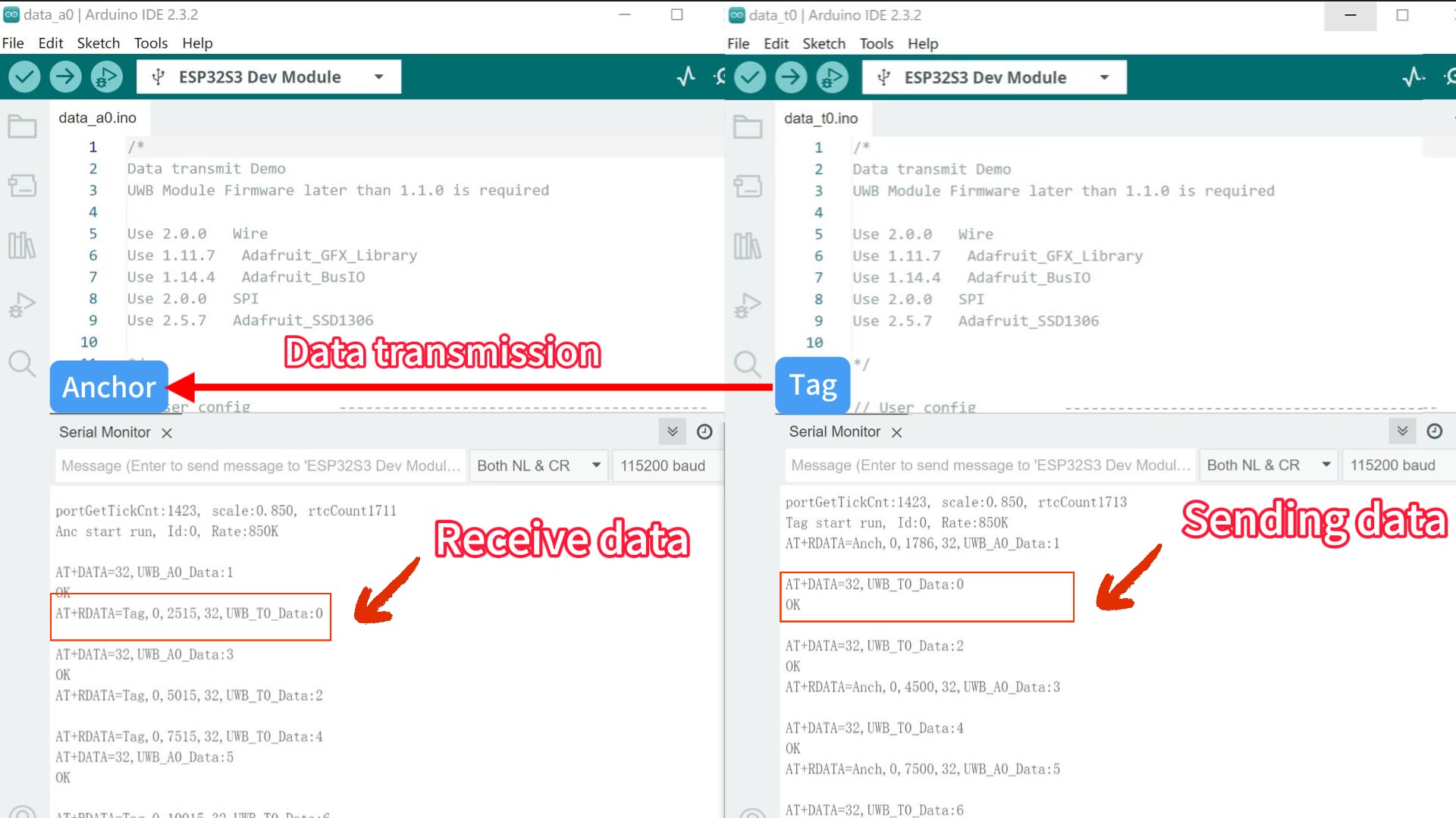
3. Data transmission
This is an example of Anchor and Tag sending data to each other, with Anchor sending incremental odd numbers to Tag and Tag sending incremental even numbers to Anchor.
Note: A firmware update is required before using this feature. Firmware update method you can find in readme.
Set the board to Tag0
Open the data_t0 by Arduino IDE.
Use Type-C USB cable to connect the board and PC, and select the development board "ESP32 Dev Module" and the port.
Verify the code and upload.
Set the board to Anchor0
Open the data_a0 by Arduino IDE.
Use Type-C USB cable to connect the another board and PC, and select the development board "ESP32 Dev Module" and the port.
Verify the code and upload.
When it is successful,open the Arduino IDE serial monitor, and you can see the A0 and T0 send data to each other.
Related AT Instructions:
sendData("AT?", 2000, 1);//Serial port test
sendData("AT+RESTORE", 5000, 1);//Clear all configuration information

sendData(config_cmd(), 2000, 1);//AT+SETCFG=0,0,0,0;
sendData(cap_cmd(), 2000, 1);//AT+SETCAP=10,25,1;

sendData("AT+SETRPT=0", 2000, 1);//Turn off distance data
sendData("AT+SAVE", 2000, 1);//Save the configuration parameters
sendData("AT+RESTART", 2000, 1);//Reset module
You can modify the AT instructions to get the Anchor or Tag that you want to define.
AT+SETCFG=0,0,0,0;//ID:0; Role:Tag; Communication rate 850K;
Set the basic module parameters using "AT+SETCFG=(x1),(x2),(x3),(x4)"
x1:Device ID(Anchor 0-7,Tag 0-31)
x2:Device Role(0:Tag / 1:Anchor)
x3:Equipment communication rate(0:850K / 1:6.8M,Default:6.8M)
x4:Range filtering is enabled(0:Close / 1:Open)
When you want data transfer, you must be set to extended packet mode.
AT+SETCAP=10,25,1;
//10-->Tag capacity:10;
//25-->850K,Minimum single slot time 25ms for extended packet.
//1-->Set extended packet mode.
Set system base station/label capacity (refresh rate)/Whether the transmitted packet is in extended mode using "AT+SETCAP=(x1),(x2),(x3)"
x1:Tag capacity (default: 10, maximum: 64)
x2:Time of a single time slot (6.8M not less than 10ms,850K not less than 15ms)
X3:extMode, whether to increase the passthrough command when transmitting.(0: normal packet when communicating; 1: extended packet when communicating)
Note:Time of a single time slot are related to the equipment communication rate:
-
6.8M, Minimum single slot time 10ms for normal packet, Minimum single slot time 10ms for extended packet.
-
850K. Minimum single slot time 15ms for normal packet, Minimum single slot time 25ms for extended packet.
Send data using "AT+DATA=(x1),(x2)".
x1:Length of transmitted data
x2:Transmitted data
Note:Only available when set to extended packet mode. Supporting up to 32 bytes of data transfer.
receive data using "AT+RDATA=(x1),(x2),(x3),(x4),(x5)".
x1: Tag or Anchor
x2: Anchor or Tag ID
x3: Device Local Time
x4: Length of transmitted data
x5: Transmitted data
Note AT command details please check Makerfabs_UWB_AT_Module_AT_Command_Manual(v1.0.8).pdf.
FAQ
You can list your questions here or contact techsupport@makerfabs.com for technology support. Detailed descriptions of your question will be helped to solve your question.
Q: How can we know the X-Y position of a tag if ESP32 UWB is supporting only 1 Tag with 1 Anchor?
A: 1 anchor can not position 1 tag, at least 3 anchors are needed, we have a blog for that.