Lora Soil Moisture Sensor V3
Introduction
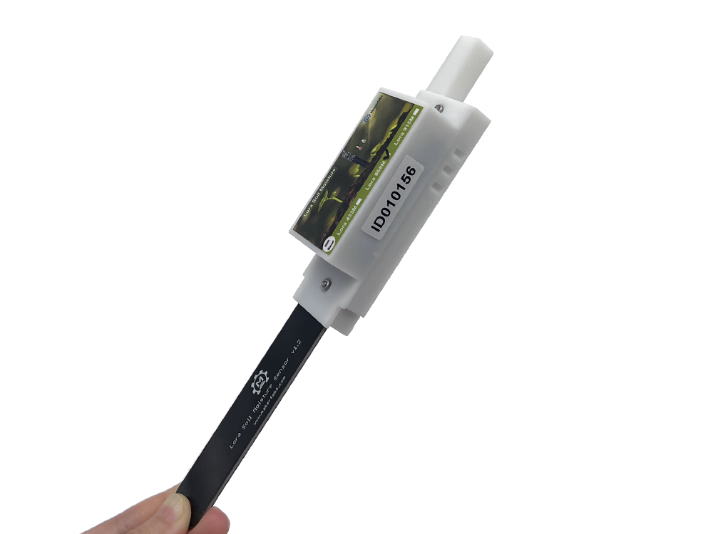
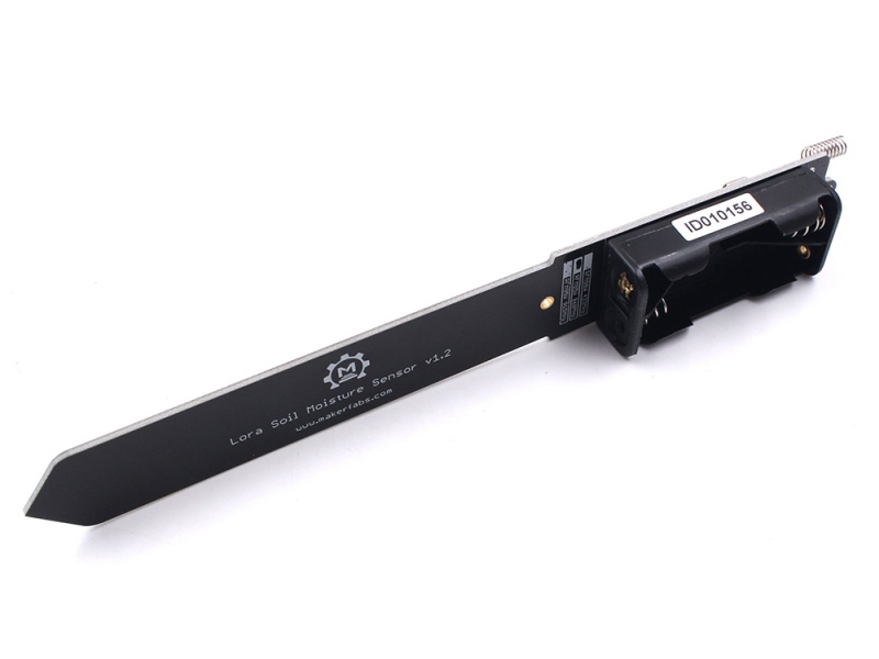
The Lora soil moisture sensor V3 is based on Atmel's Atmega328P, it collects local air temperature/ humidity with sensor AHT10, and detects the soil humidity with capacitor-humility measurement solution. It can transmit the local environment data to the gateway or devices with the Lora communication, and it suits for the applications such as smart-farm, irrigation, agriculture, etc.
In applications, always you do not need to check the air/soil state continuously, have a test of them for few seconds after then minutes/hours sleeping is normally Ok for most projects. To save power, there the Air/ Soil measuring functional could be shut down in the working, so they can be only powered ON a short time and then a long time power off. With MCU in sleeping mode and low power consumption Lora module, this module can work with 2 AAA batteries for more than one year. Besides, this sensor is coated with waterproof paint, which makes it working longer in wet soil.
Model:LSMS092DV3
Features
- Wireless Lora Transceiver
- Soil Moisture Measurement based on capacitive Testing
- Unique ID
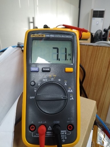
- Low power: 7.1uA when sleeping. 2 years working life with 2xAAA battery
- Onboard AHT10 sensor to monitor air temperature and air humidity
- Onboard Battery Voltage Measurement
- Full Open Source- all hardware and software open at GitHub
- Compatible with Arduino
- Supply power voltage: 2.0V~3.3V
- 3D printing case
What is hardware changed
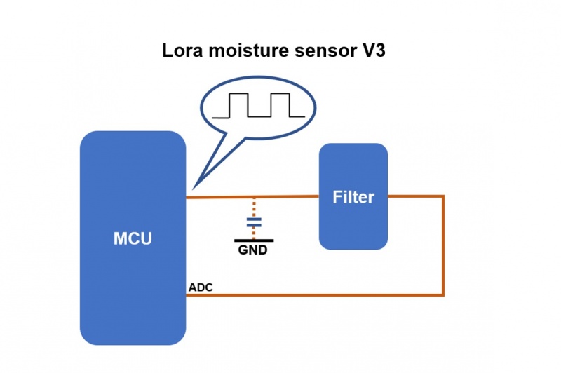
For the V2 version, the 555 IC will generate square wave that the wave into low pass filter composed of a resistor and a capacitor made by soil and PCB probe. As the moisture of the soil changes, the equivalent voltage of the capacitor will change. So the moisture can be measured by detecting the voltage of the capacitor. As the picture showed, the difference between the V2 and V3 is the generator of the square wave. V3 generates the square wave by the MCU replacing the 555 IC, it can get the same effect as V2. Besides, removing the 555 IC will reduce the power consumption that increases the battery life.
Power consumption
| Lora Soil Moisture Sensor V2 | Lora Soil Moisture Sensor V3 | |
|---|---|---|
| Standby Current | 680uA | 7.1uA |
| Service life (two AAA Batteries) | About 30 days | About 2 years or more |
Lora Soil Moisture close the PWM outputs and ADC(It’s important, ADC affects some of the power consumption) when sleeping, microcontroller goes into sleeping mode after Lora’s sleep. Wake up by the internal time, get the value of the air temperature and relative humidity from AHT10. Open the PWM outputs and ADC to measure the soil moisture and battery voltage. Then send them out via Lora. Repeat the work progress all the time. The most energy is consumed when measuring the moisture level and transmit to LoRa receiver. Much of the time is in Low power mode. The default sleep time depends on the Macro SLEEP_CYCLE. When SLEEP_CYCLE is defined as 450, sleep time is (450+1)*8s=3608s, almost 60 minutes. Then send the data out about 2 seconds.
//Set sleep time, when value is 1 almost sleep (1+1)*8=16s, when value is 450, almost 1 hour.
#define SLEEP_CYCLE 450
We tested the average power consumption when working is 9.88mA and the low power consumption when sleeping is 7.1uA. If using 1000mAh 2*AAA battery, it can be worked for more than 77821 hours(more than 3 years) in theory. However, it needs to be noticed that the final lifetime depends on the life of the battery and PCB. Also, you can change sleep time (the SLEEP_CYCLE value in the code) as your requirement.
Coat
When the sensor is used in the wet soil for a long time, the PCB probe buried in the ground would be more and more damper, and it would cause the inaccuracy of measurement at the end of the detection. To improve the measurement accuracy and extend the service life, we made a waterproof coating, that can provide waterproof protection and stop the PCB spoilage for a time.
Typical Output
It can distinguish some of the states according to the analog value. With 10 pcs soil moisture sensors, we get the typical output, for your alarm reference.
| Conditions | Range | Analog |
|---|---|---|
| In air | 801~1000 | 884 |
| Dry | 781~800 | |
| Slight wet | 751~780 | |
| Moist | 681~750 | |
| Very moist | 601~680 | |
| Soaked | 500~600 | 560 |
Note: The analog data get when powered by 3.0V
Usage
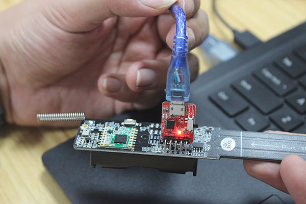
In order to meet the requirement of the low power consumption, we provide the firmware for the low consumption and the firmware has been uploaded to the sensor before shipping. So you can use the sensor directly after unpacking it. Note that if you want to re-upload the code, you need a USB-to serial tool.
- The firmware is available on Github.
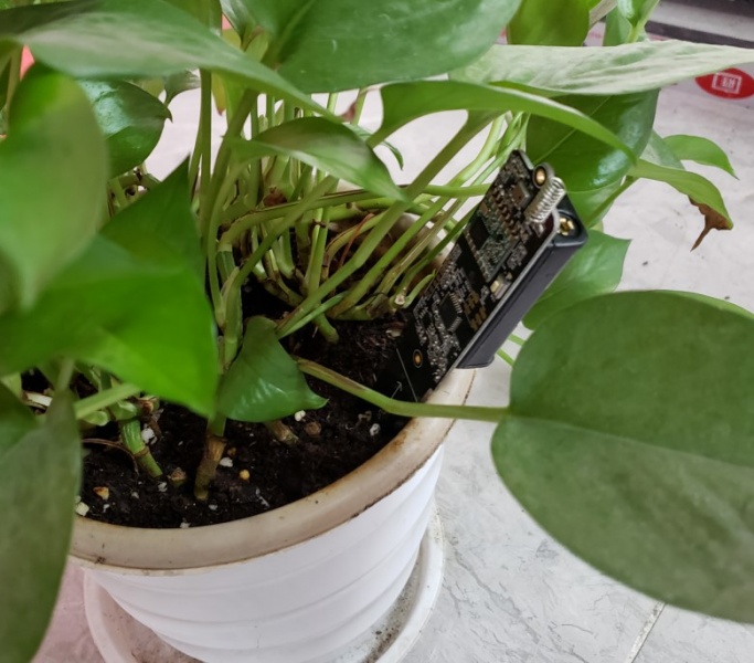
- When you power the sensor with 2 AAA batteries, it will transmit the soil moisture measurement through LoRa communication. Then the sensor will enter the sleep mode and wake up to work in 75 minutes.
- There is an ID pasted on the case or PCB, and we have encoded a unique ID in the firmware for each sensor.
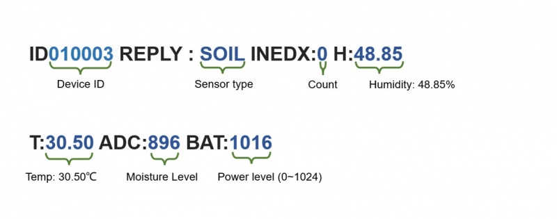
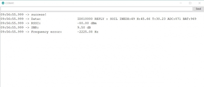
- You can use any LoRa device with the same frequency to receive the sensor measurement. The measurement LoRa transmitted will be made of ID, temperature, humidity and moisture,
such as: ID010003 REPLY : SOIL INEDX:0 H:48.85 T:30.50 ADC:896 BAT:1016
we used the internal 1.1V as ADC reference voltage and 1.1V related to ADC value 1023.
Next, it will show you 3 LoRa receivers to receive the sensor measurement.
1.Use Maduino LoRa radio to get temperature and moisture, and show them on the serial monitor.
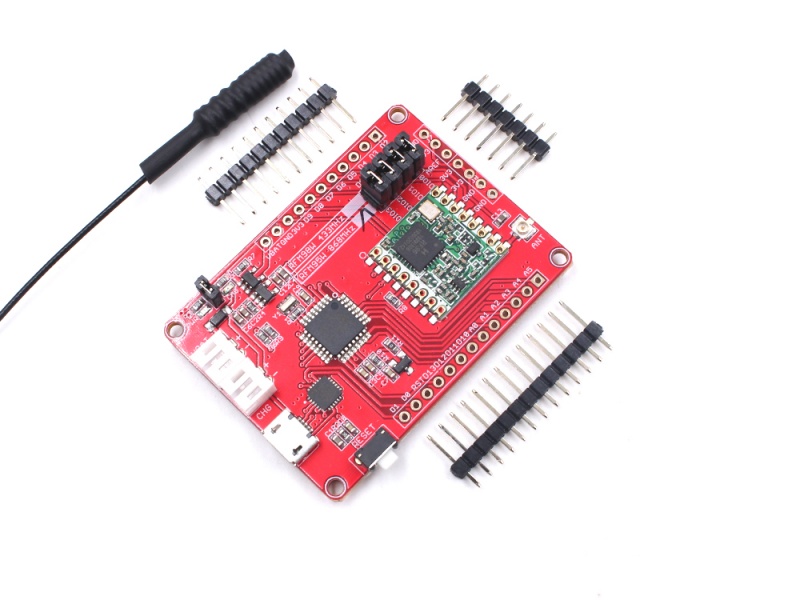
- Prepare the module with the same frequency (I used the 433Mhz one).
//Lora set
//Set Lora frequency
 #define FREQUENCY 434.0
// #define FREQUENCY 868.0
//#define FREQUENCY 915.0
- It is required to upload the sketch to the module as a Lora receiver. The sketch can be obtained from here.
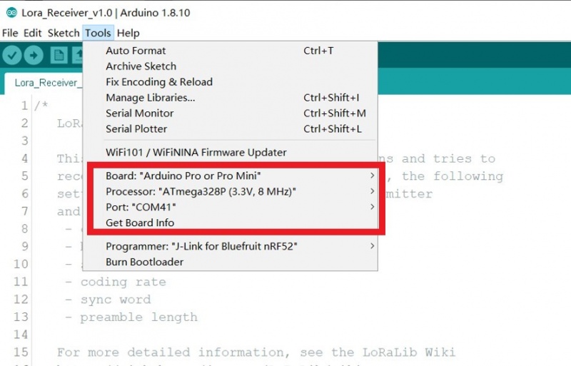
-
Open the sketch by Arduino IDE, select the "Arduino pro or pro mini" development board, "Atmega328P(3.3V,8MHz)" and the port.
-
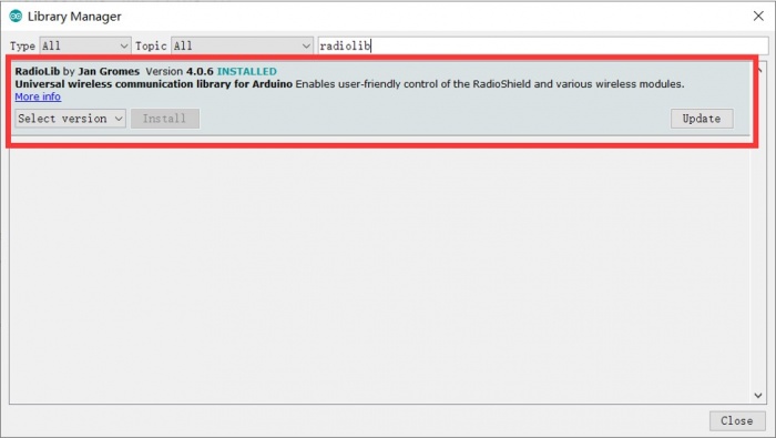
Install the RadioLib.h library to support the Lora module working.
- Upload the sketch to the module.
- Check the serial monitor of the Arduino IDE, that it will display the sensor measurement when you reset the sensor.
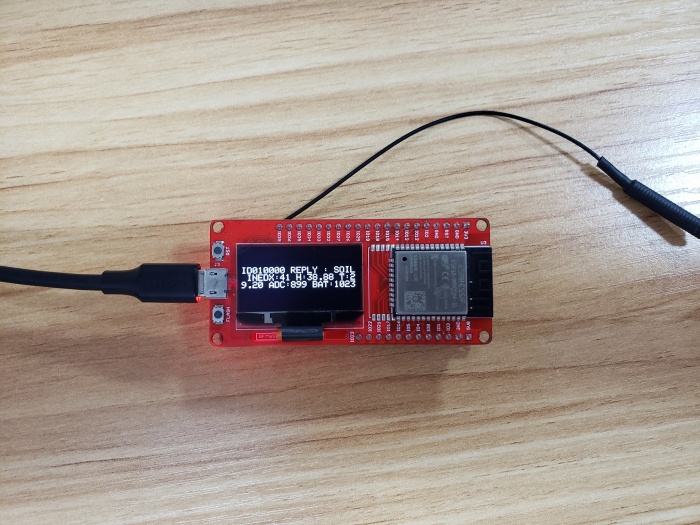
2.Use MakePython LoRa to receive the data from the sensor, and show it on the screen.
Note: If you purchased MakePython Lara before December 2020, you need to solder four 0Ω±5% 0603 resistors at R6, R7, R9, R10 or solder them with solder wire directly(RadioLib library requires). Purchases made after December 2020 are not required.
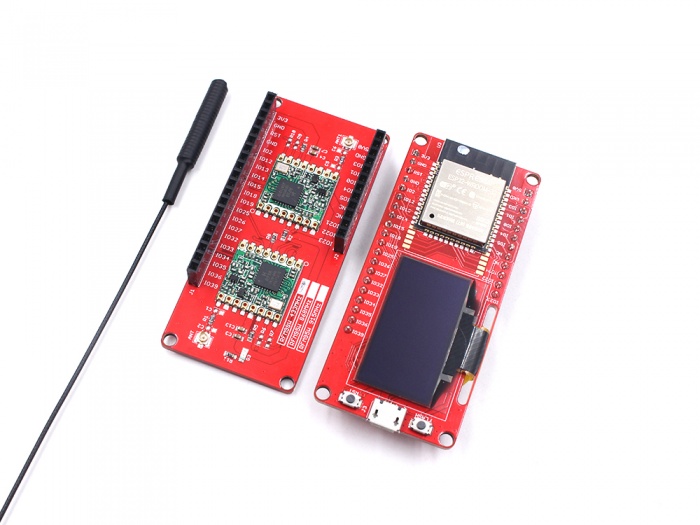
- Prepare MakePython ESP32 and MakePython LoRa with the same frequency, and combine with two boards by the pin.
- Connect MakePython ESP32 to PC by the USB cable.
- Get the receiver sketch from Github, and open it by Arduino IDE.
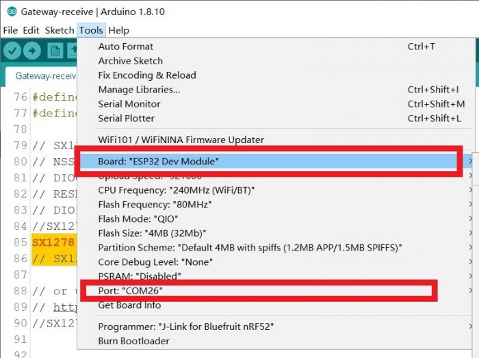
- Select the development board "ESP32 Dev Module" and the port. (if you have not installed the ESP32 library, please check here to install)
NOTE: In order for the project to work normally, please install the same version. Please install the ESP32 boards supporting V1.0.6
- It is required to modify the frequency configuration in the code.
#define FREQUENCY 434.0  // 868.0 or 915.0

SX1278 radio = new Module(LORA_CS, DIO0, LORA_RST, DIO1, SPI, SPISettings());  //433Mhz
// SX1276 radio = new Module(LORA_CS, DIO0, LORA_RST, DIO1, SPI, SPISettings());   // 868Mhz or 915Mhz
- Upload the code to MakePython ESP32.
- When you reset the LoRa Soil moisture sensor, you will see the measurement shown on the screen.
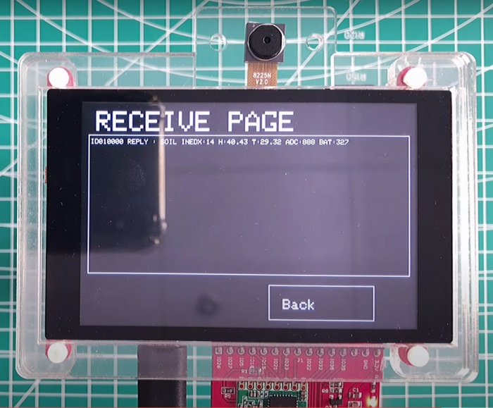
3.Use ESP32 LoRa controller (ESP32 3.5inch display and LoRa Expansion board) to receive the data and show it on the screen.
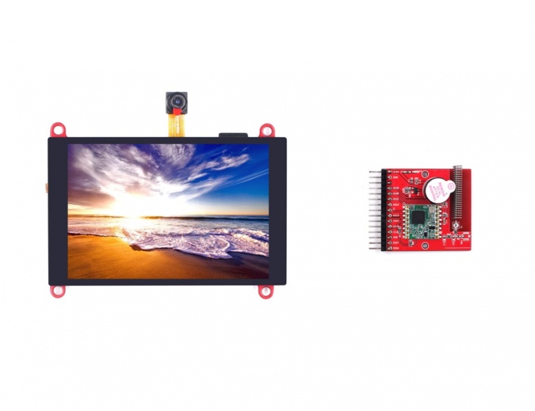
- Prepare ESP32 3.5 inch display and LoRa Expansion module, and plug the Expansion module to display by the pin.
- Connect ESP32 to PC by the USB cable for loading sketch and power.
- Get the receiver sketch(ESP32TFT3.5-LORA.ino) from GitHub, open the sketch by Arduino IDE.
- As the previous demo show, install the library, select the development board and other configurations.
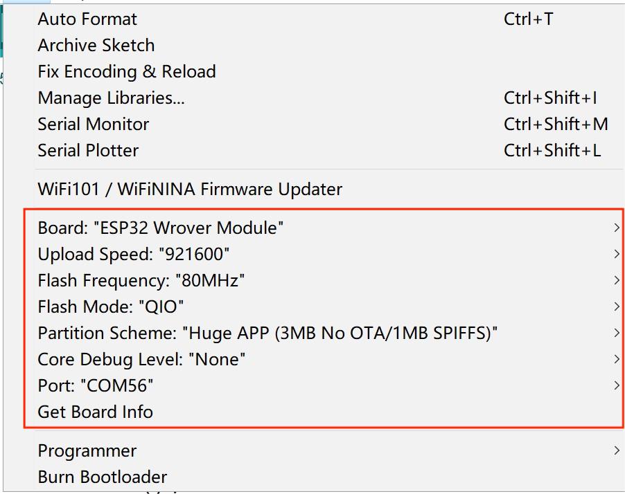
- Modify the LoRa frequency to yours in the code(makerfabs_pin.h), and upload the sketch to the board
#define FREQUENCY 434.0  // 868.0 or 915.0
#define BANDWIDTH 125.0
#define SPREADING_FACTOR 9
#define CODING_RATE 7
#define OUTPUT_POWER 10
#define PREAMBLE_LEN 8
#define GAIN 0
- The ESP32 LoRa controller needs to do some operations for receiving the sensor data, please check here for it. Reset the sensor, the ESP32 LoRa controller would receive the data and show it on the screen.
FAQ
You can list your question here or contact techsupport@makerfabs.com for technology support. Detailed descriptions of your question will be helped to solve your question.