MaTouch_ESP32-S3 Parallel TFT with Touch 3.5'' ILI9488
1. Introduction
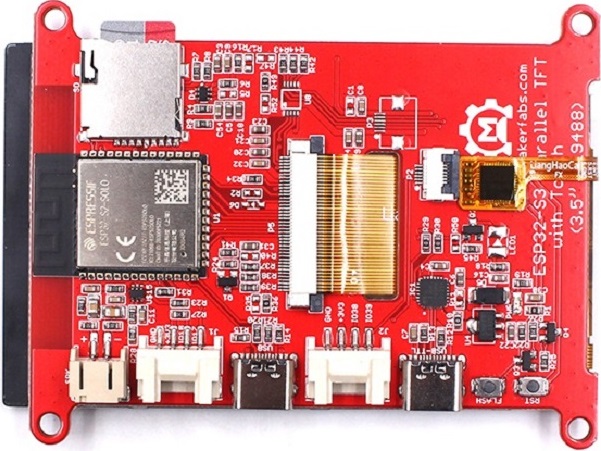
We know that the ESP32-S2 Parallel 3.5'' TFT doesn't have Bluetooth, which can make it lose some functions for short-range communication. But if we choose the ESP32 3.5" TFT Touch with Camera, some customers feedback they want a higher speed display. So we can't give up its high refresh rate for use, with the esp32-s3 published, we choose it as the main control IC to diver the TFT display.
That is why we publish this latest ESP32-S3 Parallel TFT, compares to the S2 version, not only more SRAM and ROM, the Bluetooth 5.0 make it fit for applications such as local monitoring/controlling.
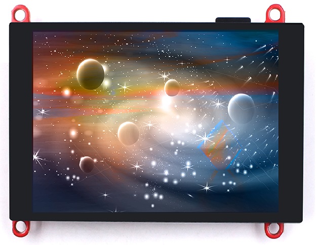
This ESP32-S3 is configured 3.5" 320x480 TFT LCD to driver ILI9488, it uses 16bits parallel line for communication with ESP32-S3, the main clock could be up to 20MHz, making the display smooth enough for video displays. With this display, you can freely create more IoT display projects.
Model:ESP32S335D
2. Features
- Controller: ESP32-S3-WROOM-1-N16R8, PCB Antenna, 16MB Flash, 8MB PSRAM
- Wireless: Wifi& Bluetooth 5.0
- LCD: 3.5 inch TFT LCD
- Resolution: 480*320
- Color: RGB
- LCD interface: Parallel 16bit
- LCD Driver: ili9488
- Touch Panel: Capacitive
- Touch Panel Driver: FT6236
- USB: Dual USB Type-C(one for USB-to-UART and one for native USB)
- UART to UART Chip: CP2104
- Power Supply: USB Type-C 5.0V(4.0V~5.25V)
- Button: Flash button and reset button
- More interface: 1I2C; 11GPIO
- Backlight Controller: Yes
- MicroSD: Yes
- Arduino Support: Yes
- Type-C Power Delivery: Not Supported
- Operation temperature: -40℃ to +85℃
- Dimension: 66mm84.3mm12mm
- Weight: 52g
2.1 About the refresh rate
Sure we know it's the best advantage is the refresh rate. Compared with ESP32-S3 SPI 3.5" TFT with Touch, It can exhibit a faster refresh rate. Now you can find out through the video below.
2.2 About the LVGL
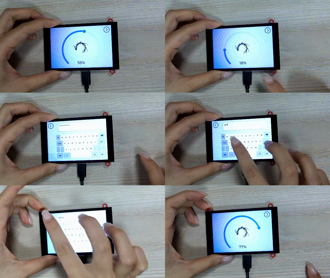
LVGL open source graphics library is a hot point in the development board with screen. Through development, we can design our own GUI. we will show an example as follows.
The open source code provide from @radiosound-com:https://github.com/radiosound-com/mak...
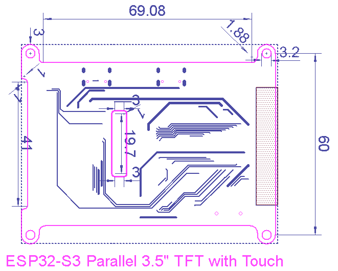
3. Dimension
4. Usage in Arduino IDE
Warning: Don't operate when in power supply on
Github:Makerfabs-ESP32-S3-Parallel-TFT-with-Touch
If you not install CP2104 driver on your PC, install CP2104 driver first CP210x Driver.
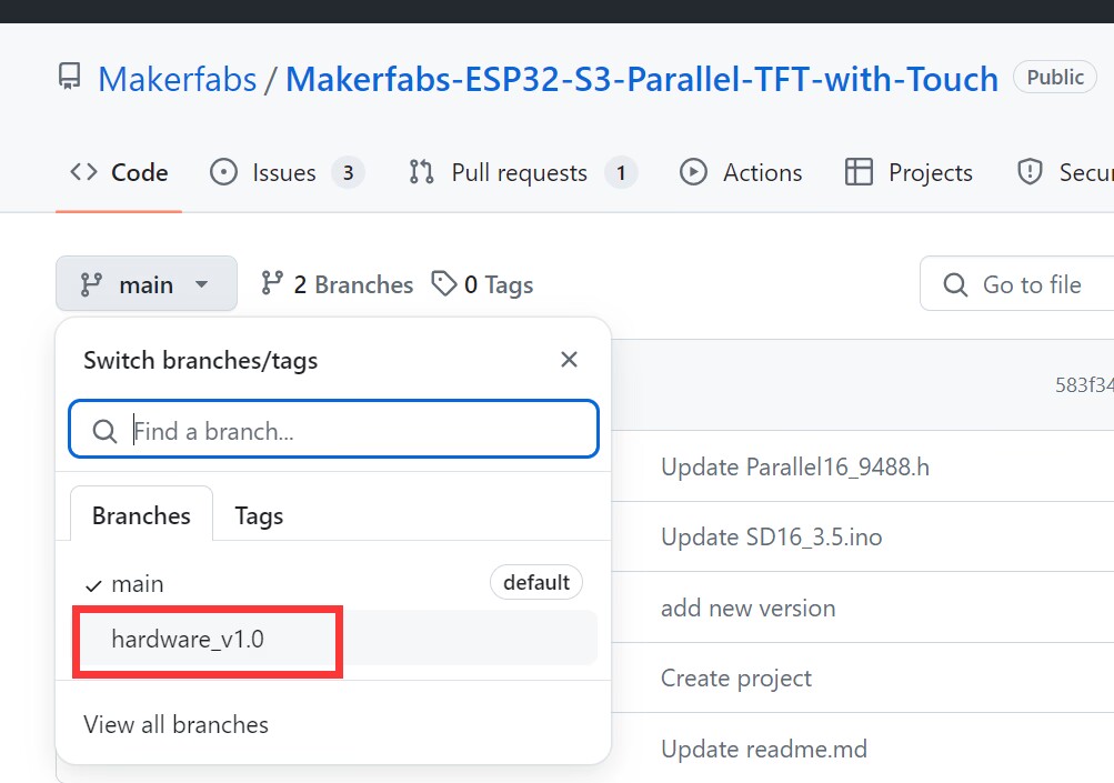
Notice: Check the hardware silkscreen to check the version number,if hardware is V1.0,Please switch to the "Hardware v1.0" branch.
4.1 Software setup
To ensure the running environment, the same version is recommended.
1.Install the Arduino IDE V1.8.19.
2.Install the ESP32 boards supporting V2.0.16
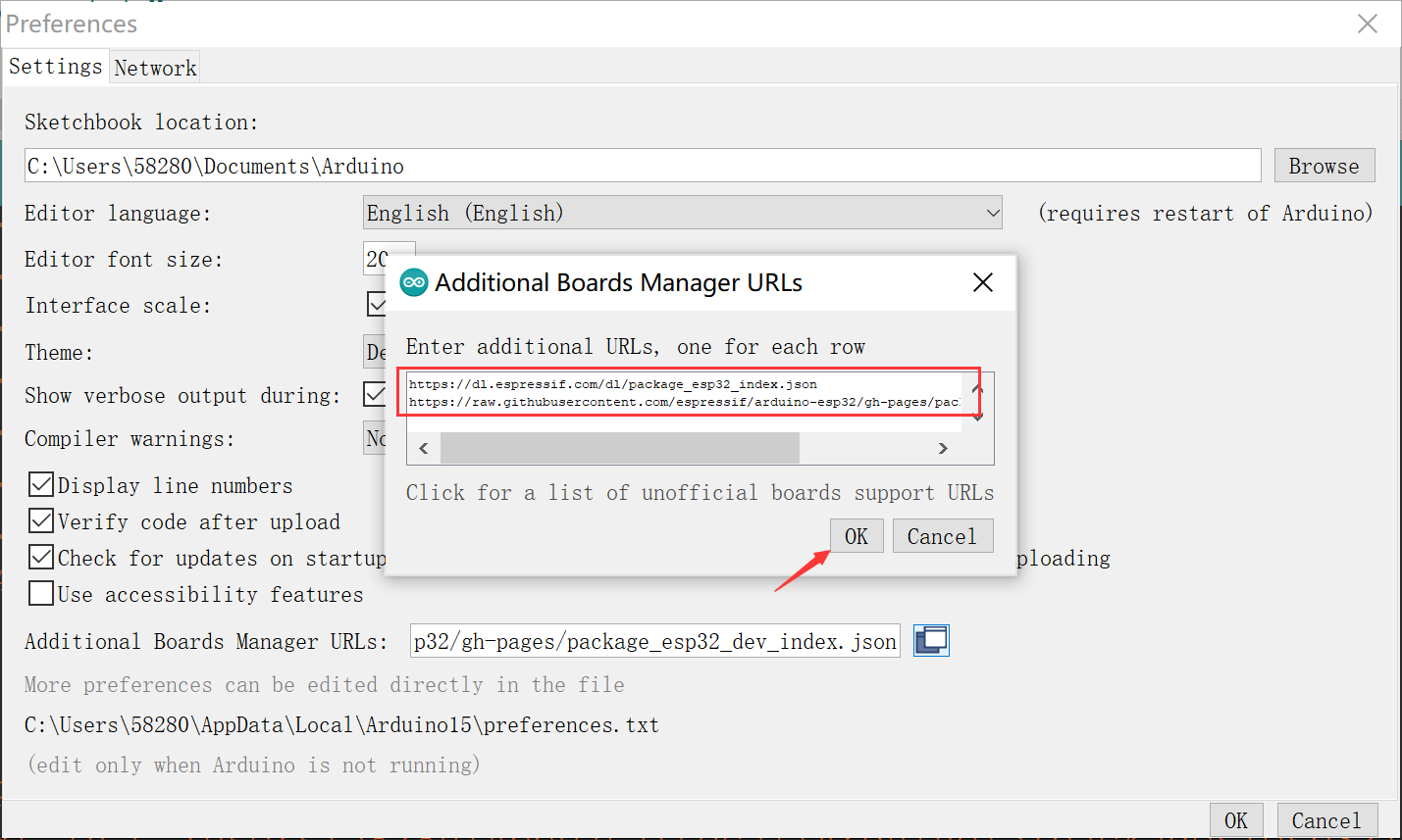
Enter the following into the “Additional Board Manager URLs” field:
- Select “File>Preferences>settings>Additional Boards Manager URLs”.
https://dl.espressif.com/dl/package_esp32_index.json
https://raw.githubusercontent.com/espressif/arduino-esp32/gh-pages/package_esp32_dev_index.json
- Click “Tools>Board>Boards Manager” to search for and install the ESP32 library:
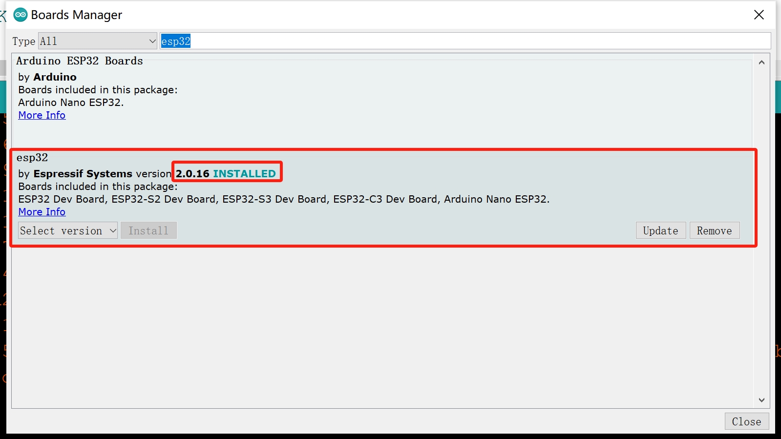
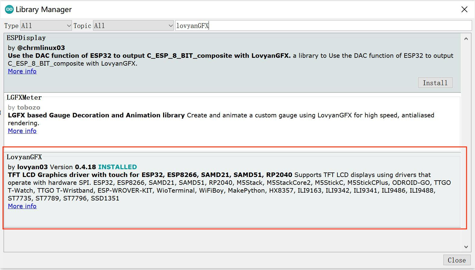
3.Install LovyanGFX library V0.4.8
- Click “Tools> Manager Libraries” to search for and install LovyanGFX library.
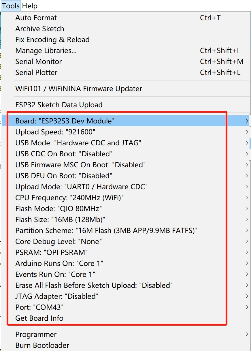
4.Select and set the parameter in the Tools menu, as the picture:
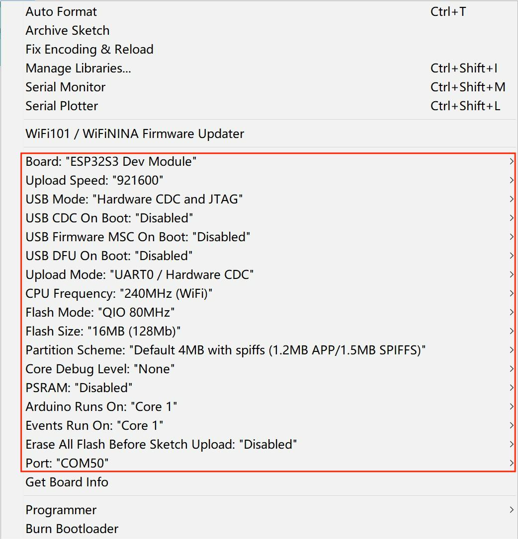
Note: Different PC has different Serial COM number
4.2 Touch_keyboard_v2 demo
In this demo, ESP32-S3 Parallel 3.5'' TFT with Touch as a USB HID to display the function of the keyboard.
So you can get the code from GitHub.
Then open the file*touch_keyvborad_V2*.
In the code, you must modify as your own WiFi-Configuration
Verify it and upload.

You can check if the version of the download library is correct.

So, we can look at this video as an example which is show the effect of ESP32-S3 Parallel 3.5" TFT with Touch as a USB HID.
4.3 SGP30_WEBSERVER Demo
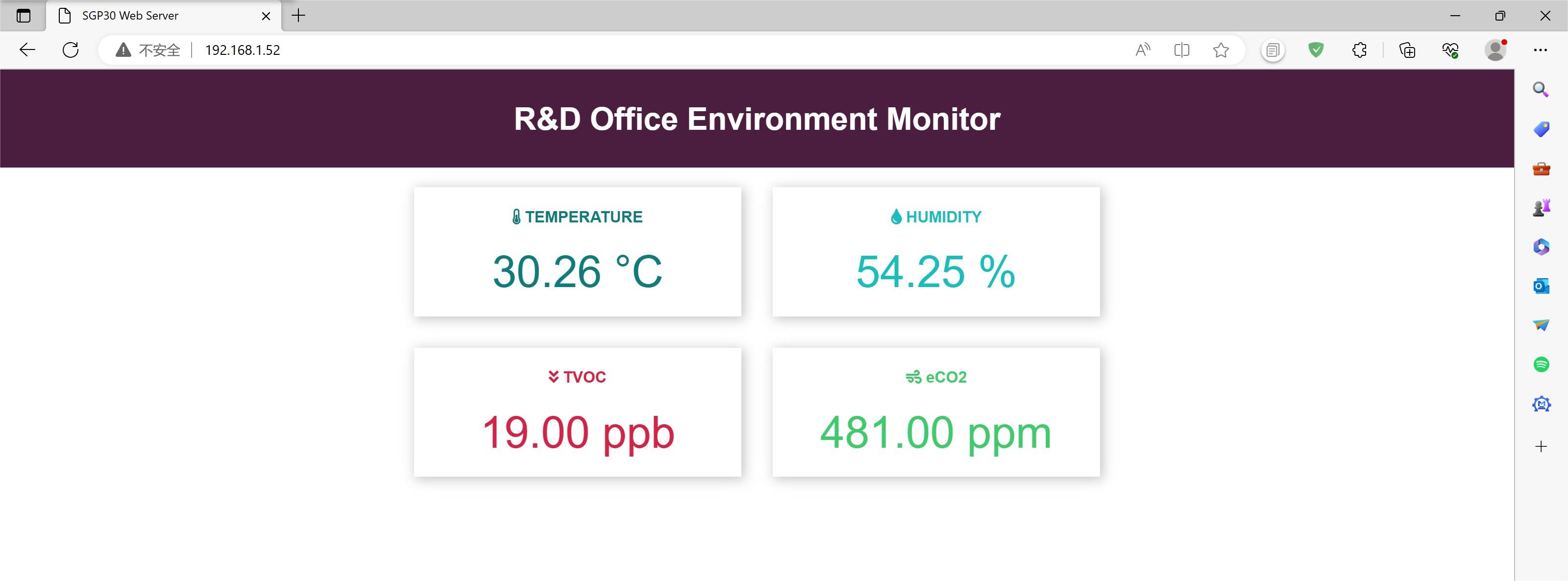
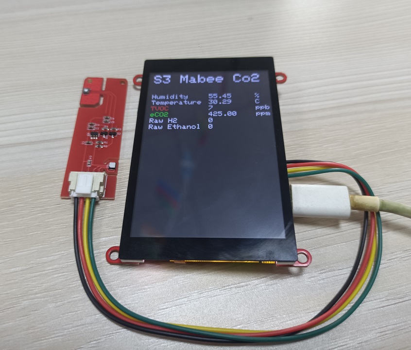
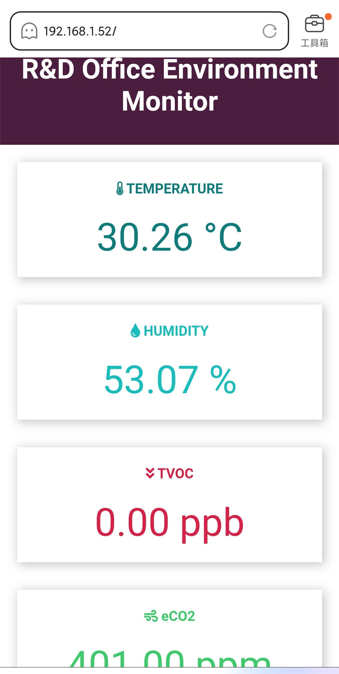
By using the Mabee CO2, we can detect the Temperature/humidity/TVOC/eCO2 in the room, and we want to make the colleague can see the measured result where in Another office. So, we try to use a web page to display the measured data, in the LAN.
Hardware Wiring
| Matouch | Mabee CO2 |
|---|---|
| GND | GND |
| +3V3 | VCC |
| IO38 | SDA |
| IO39 | SCL |
- install the ESPAsyncWebServer library and ESPAsyncTCP library in GitHub to the Arduino library.
- Open the example>>ESP32S3_dgp30_WEBSERVER_V1.2 in GitHub
- Verify and upload the code.
You can check if the version of the download library is correct.

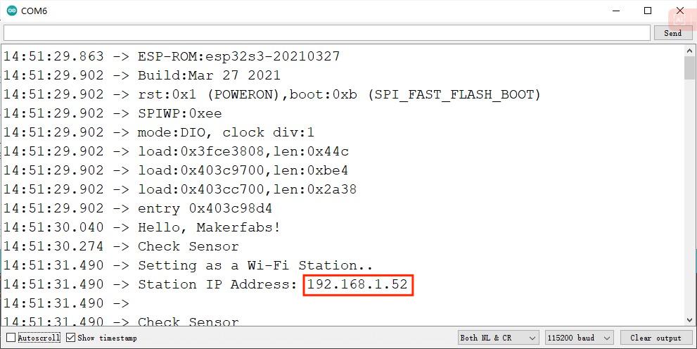
When the program is uploaded successfully, open the serial port.
- Enter this ip address in the mobile phone or website, you can see the same data as the screen.
5. Usage in VS Code & PlatformIO
Downloaded and installed PlatformIO IDE for VSCode
5.1 Touch_keyvborad_v2 demo
In this demo, ESP32-S3 Parallel 3.5'' TFT with Touch as a USB HID to display the function of the keyboard.
Download and unzip the Touch_keyvborad_V2, open this project by VS Code.
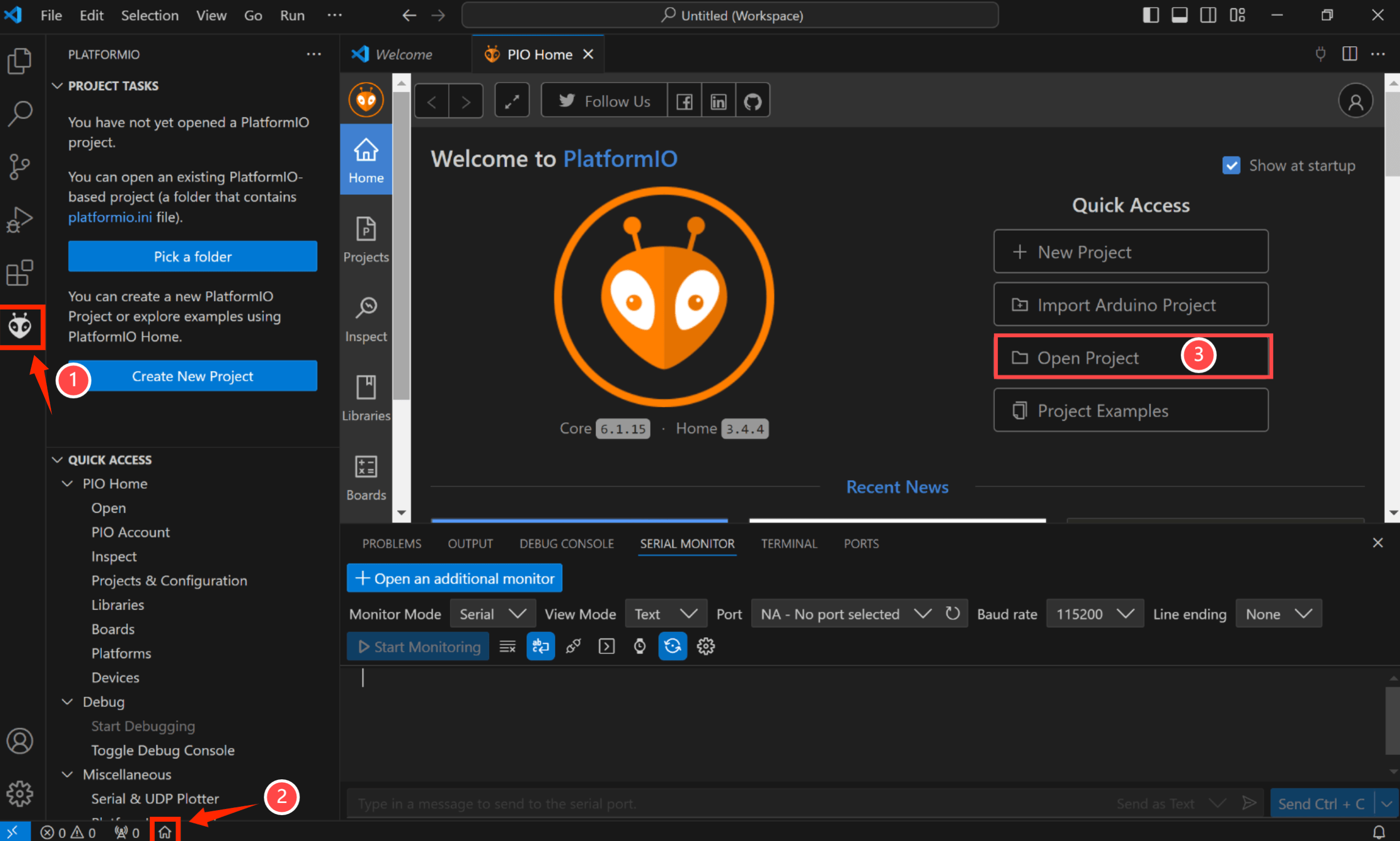
Notice: Check the hardware silkscreen to check the version number,if hardware is V1.0,Please switch to the "Hardware v1.0" branch.

Waiting for configuration project.
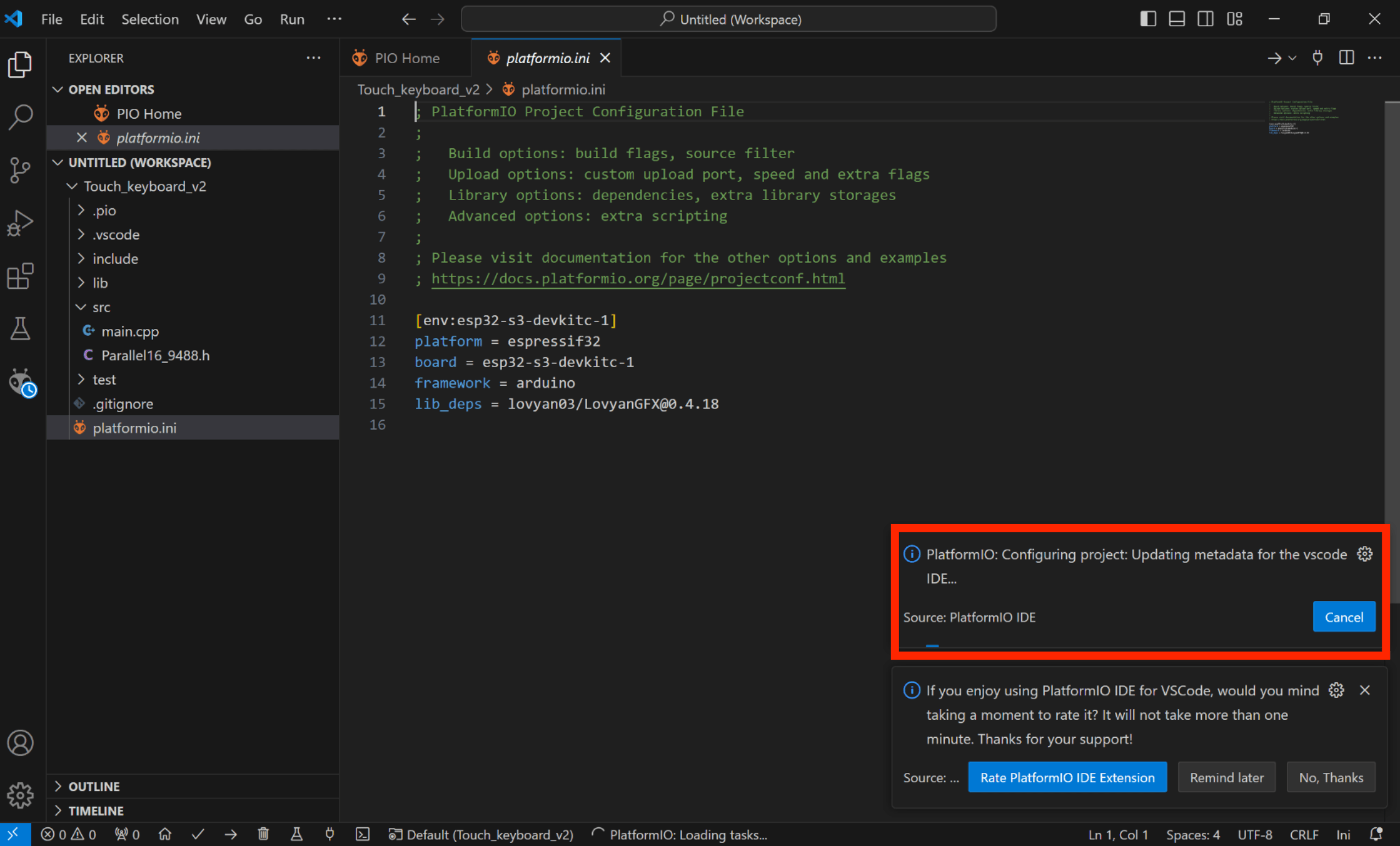
In the code, you must modify as your own WiFi-Configuration
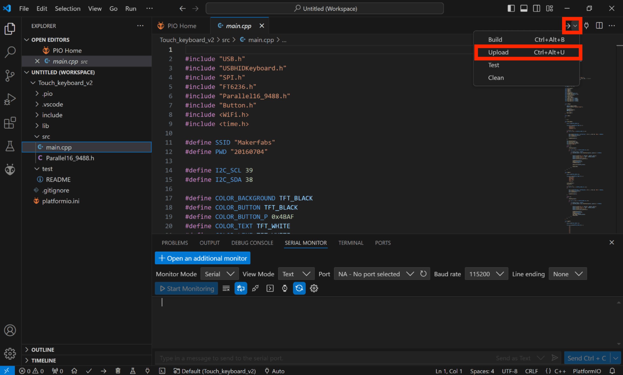
- Click "src-->main.cpp".

Verify it and upload.
Result:
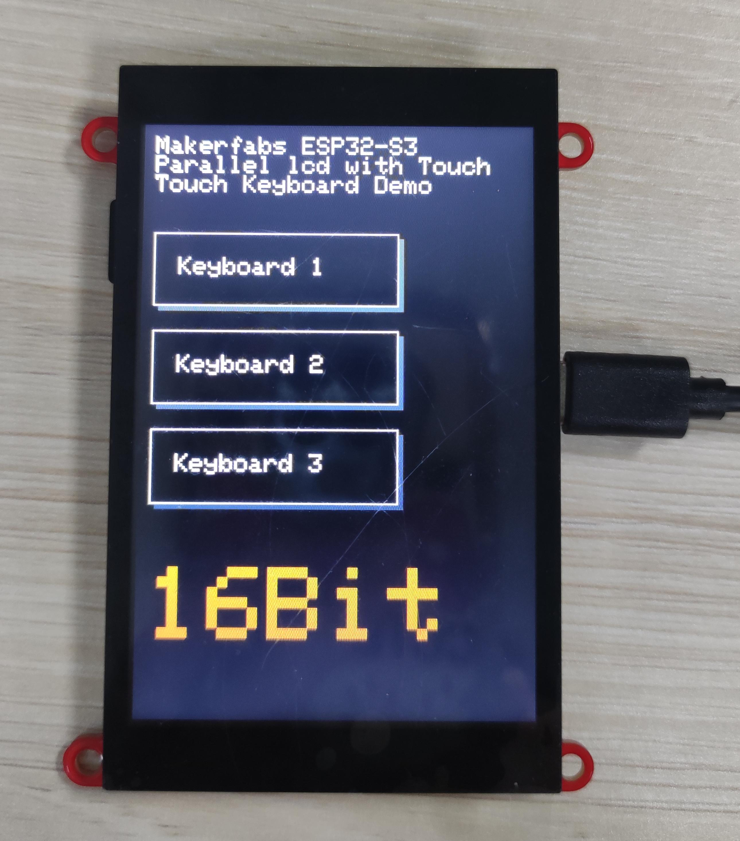
5.2 SGP30_WEBSERVER Demo
By using the Mabee CO2, we can detect the Temperature/humidity/TVOC/eCO2 in the room, and we want to make the colleague can see the measured result where in Another office. So, we try to use a web page to display the measured data, in the LAN.
Hardware Wiring
| Matouch | Mabee CO2 |
|---|---|
| GND | GND |
| +3V3 | VCC |
| IO38 | SDA |
| IO39 | SCL |
Download and unzip the ESP32S3_SGP30_WEBSERVER_V1.2, open this project by VS Code.
Waiting for configuration project.

- Click "src-->main.cpp".
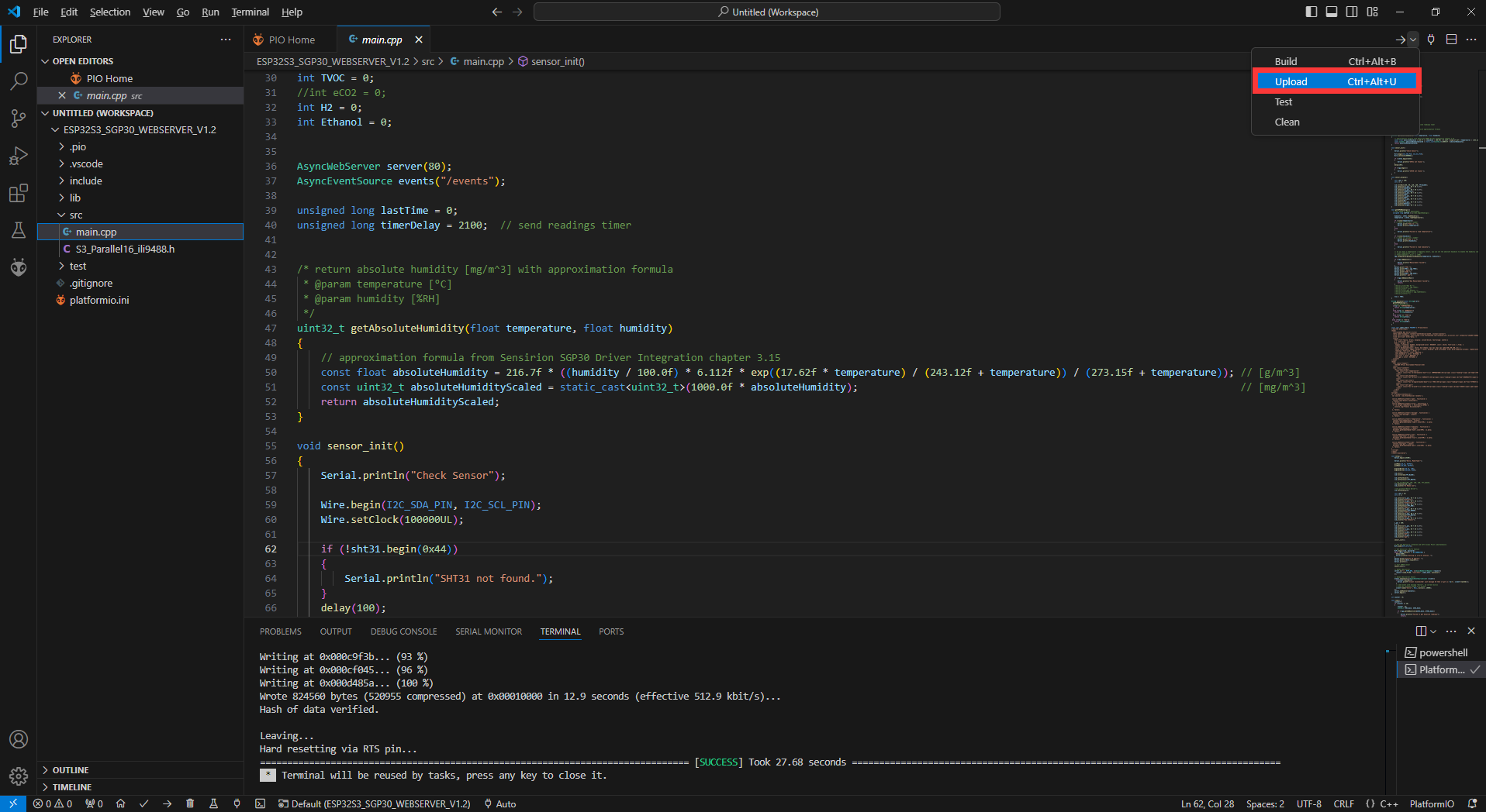
Verify it and upload. When the program is uploaded successfully, open the serial port.


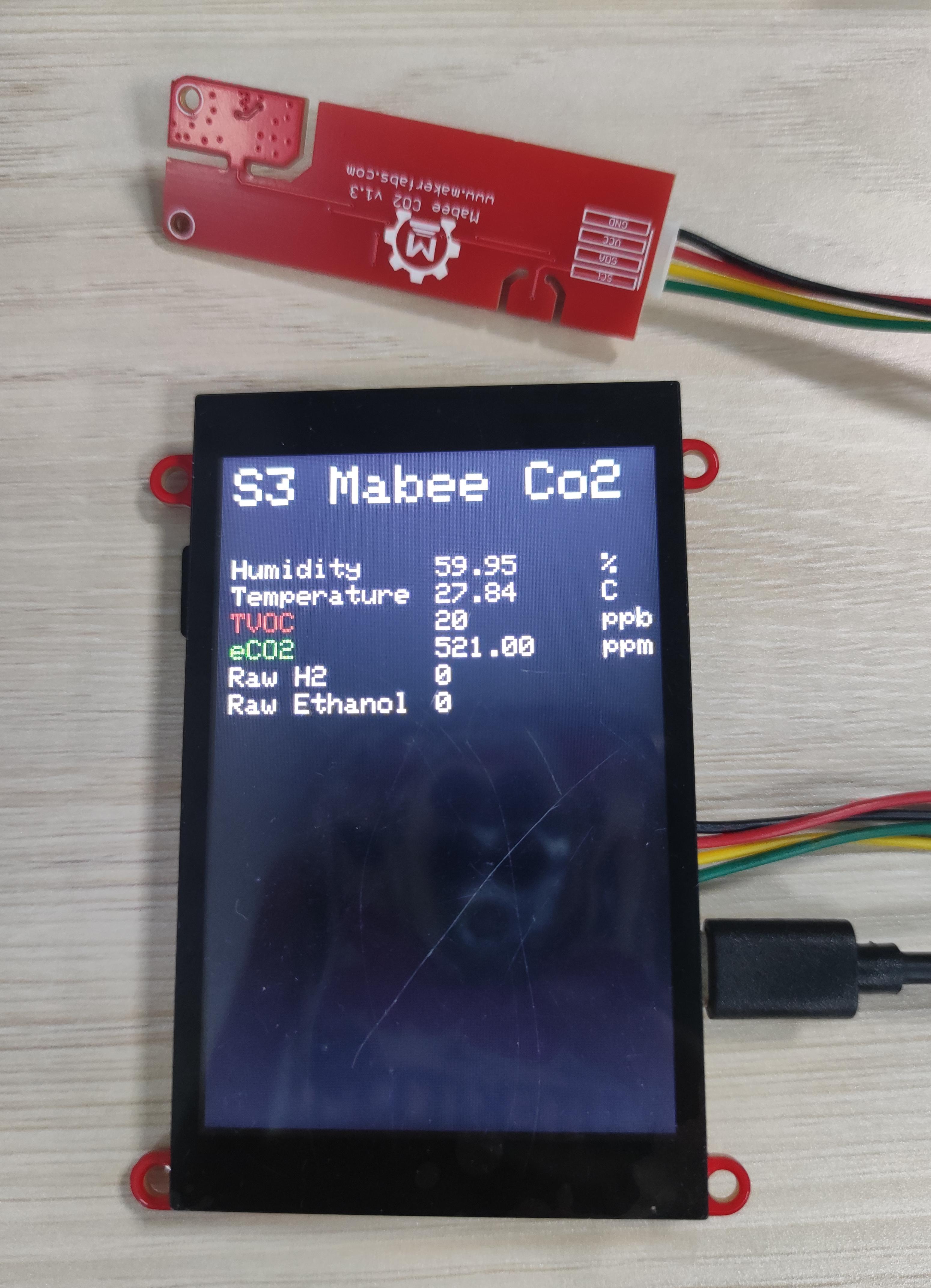
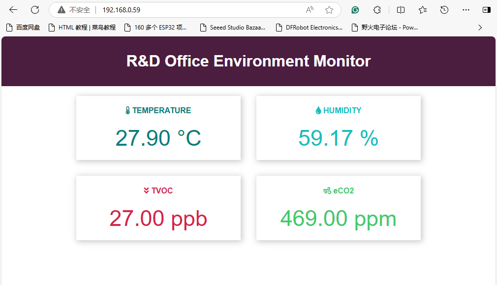
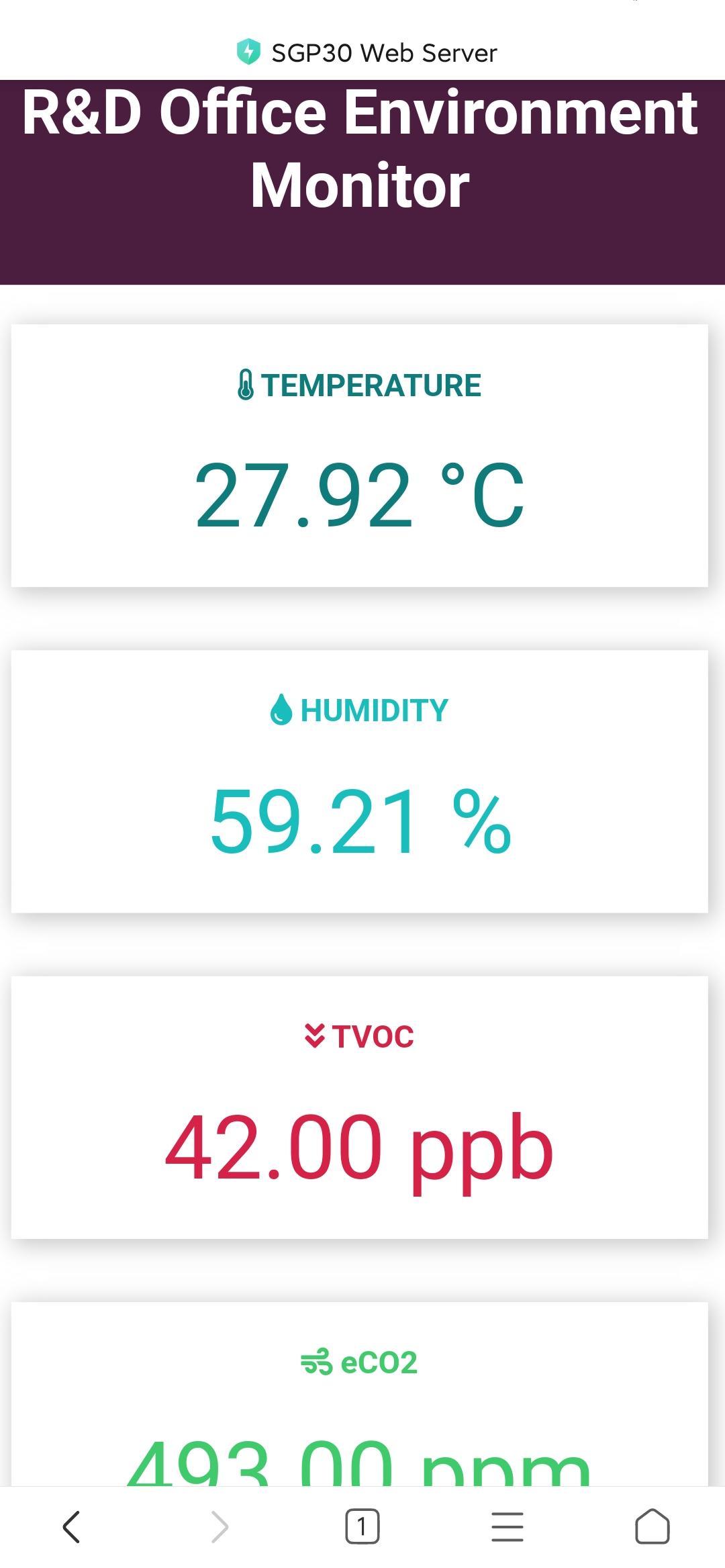
Enter this ip address in the mobile phone or website, you can see the same data as the screen.
6. Usage in SquareLine Studio
If you have not installed SquareLine Studio, please follow this guide to install.
Squareline currently only supports 4", 1.9", 2.1" screens, if you want to use other screens, you need to follow this guide to add the relevant simplified packages.
6.1 LVGL design with SquareLine Studio
1.Click on Squareline to log in to your account, or click on "Sign up" if you don't have one.
2.Create a project.
- Click “Crearte-->Makerfabs”.
- Select “MaTouch ESP32-S3 3.5inch Parallel”, modify the desired project name and location information.
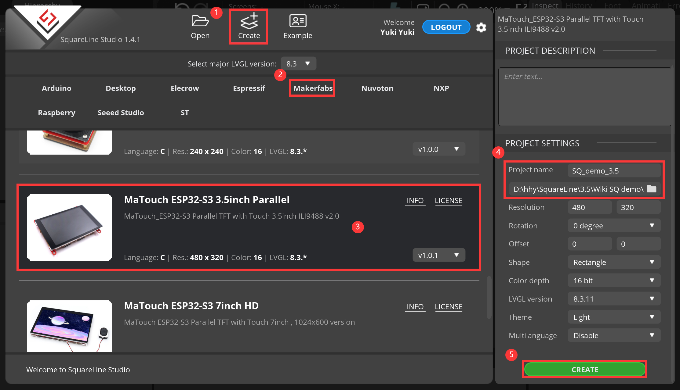
Notice: Check the hardware silkscreen to check the version number,if hardware is V1.0,Please switch to the v1.0.0.

3.Add the required images or icons.
- Click "ADD FILE INTO ASSETS" to add the images or icons you like.

4.Setting the screen background.
- Click screen, switch to the screen Settings, click "brackground", add the image to the screen.
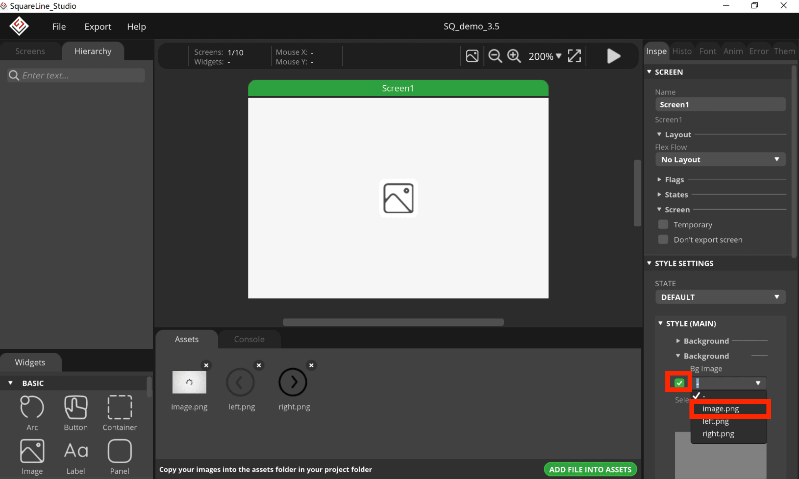
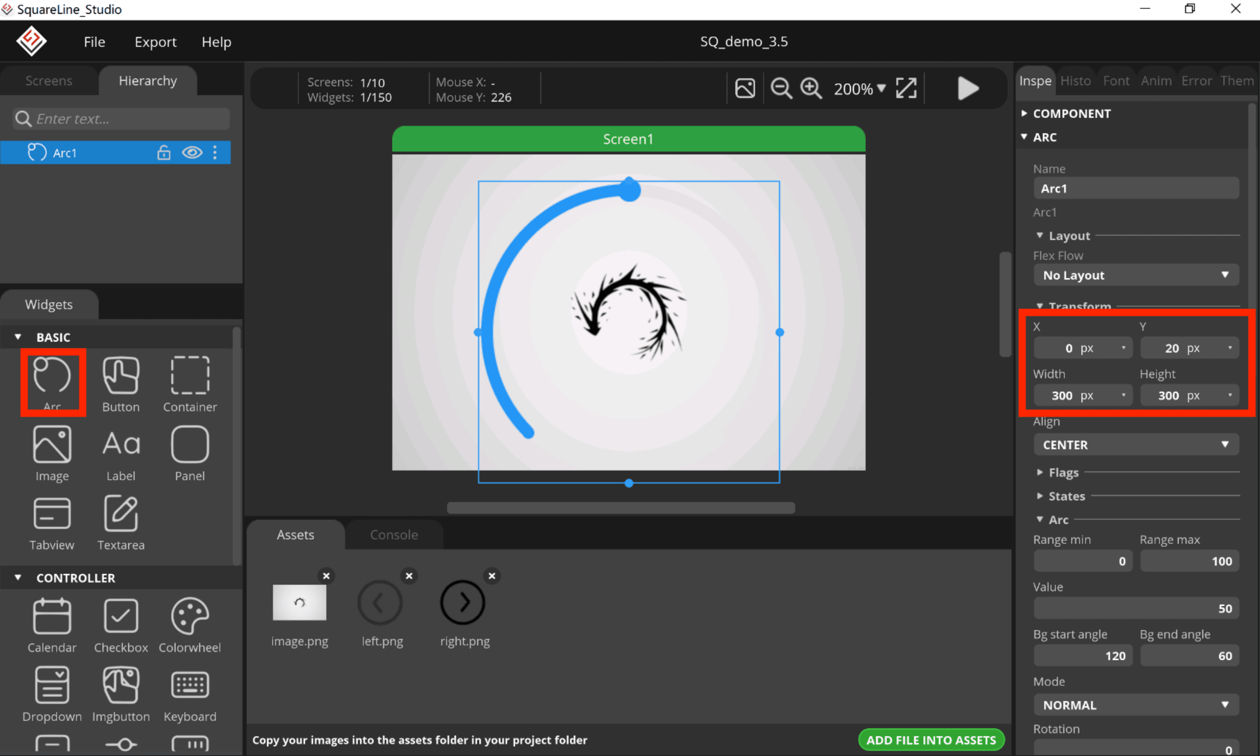
5.Add an Arc.
- Click “Arc”, and set its size and position.
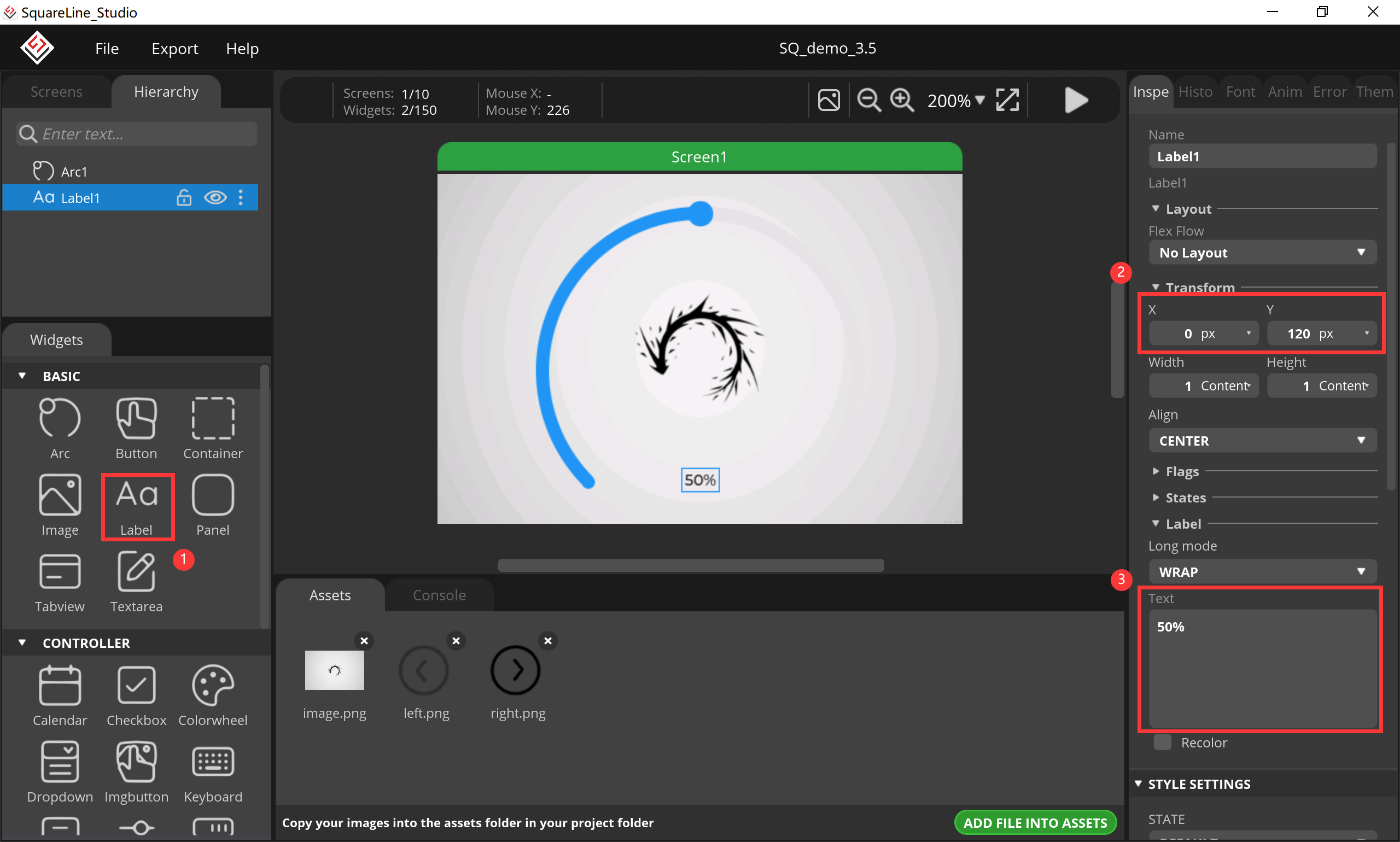
6.Add a Label.
- Click “Label”, and set its position, value and size.
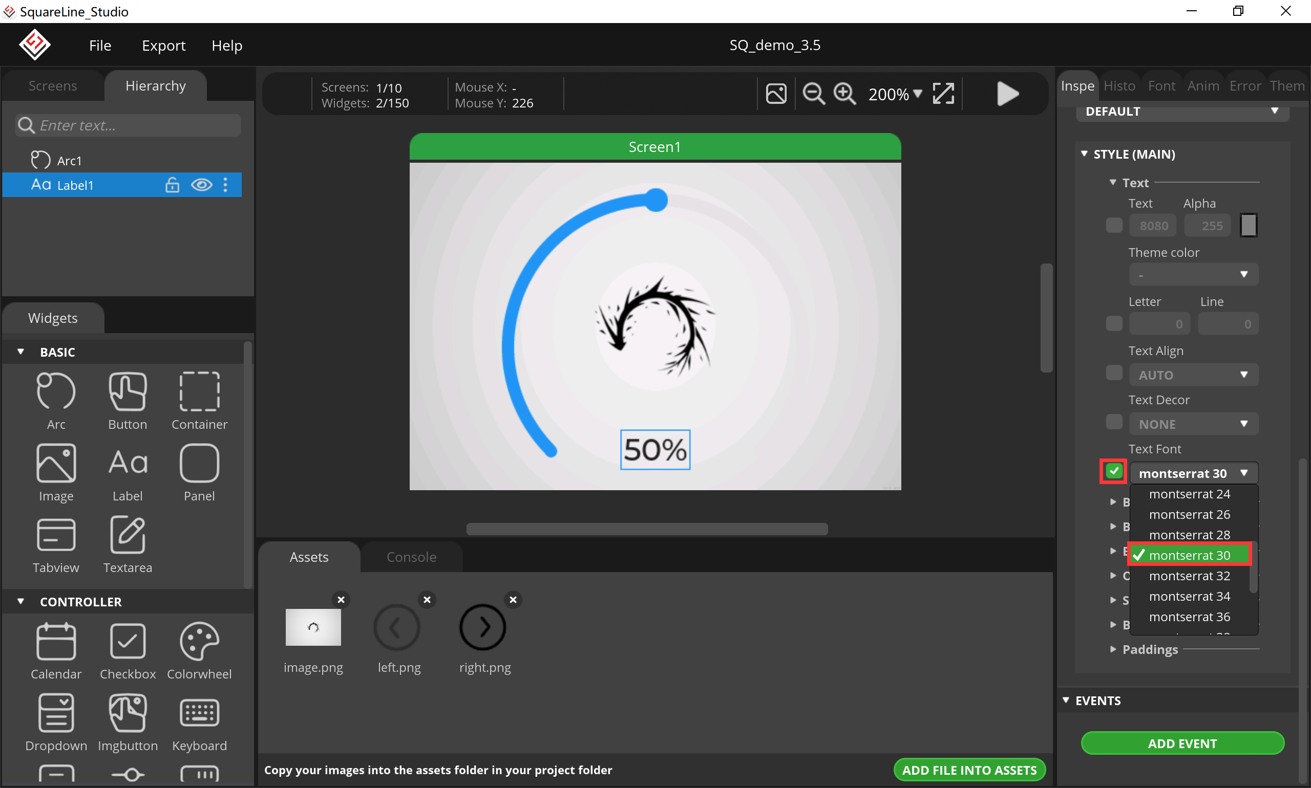
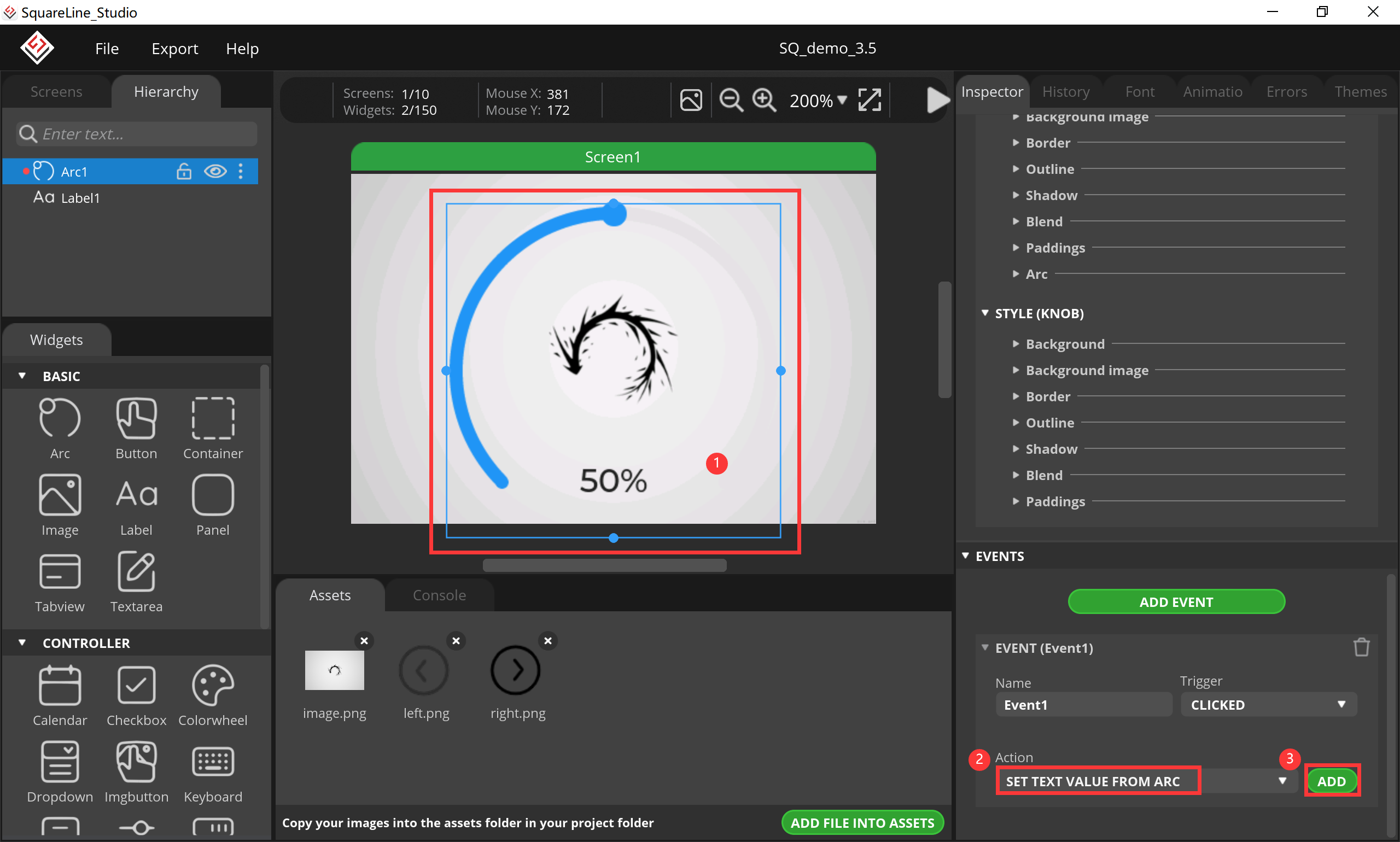
7.Add event, set text value from arc.
- Click “Arc”, select “SET TEXT VALUE FROM ARC” and click “ADD”.
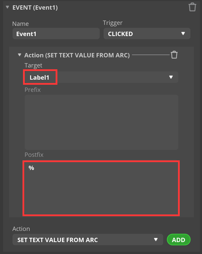
- Select “Label1”, the unit is %.
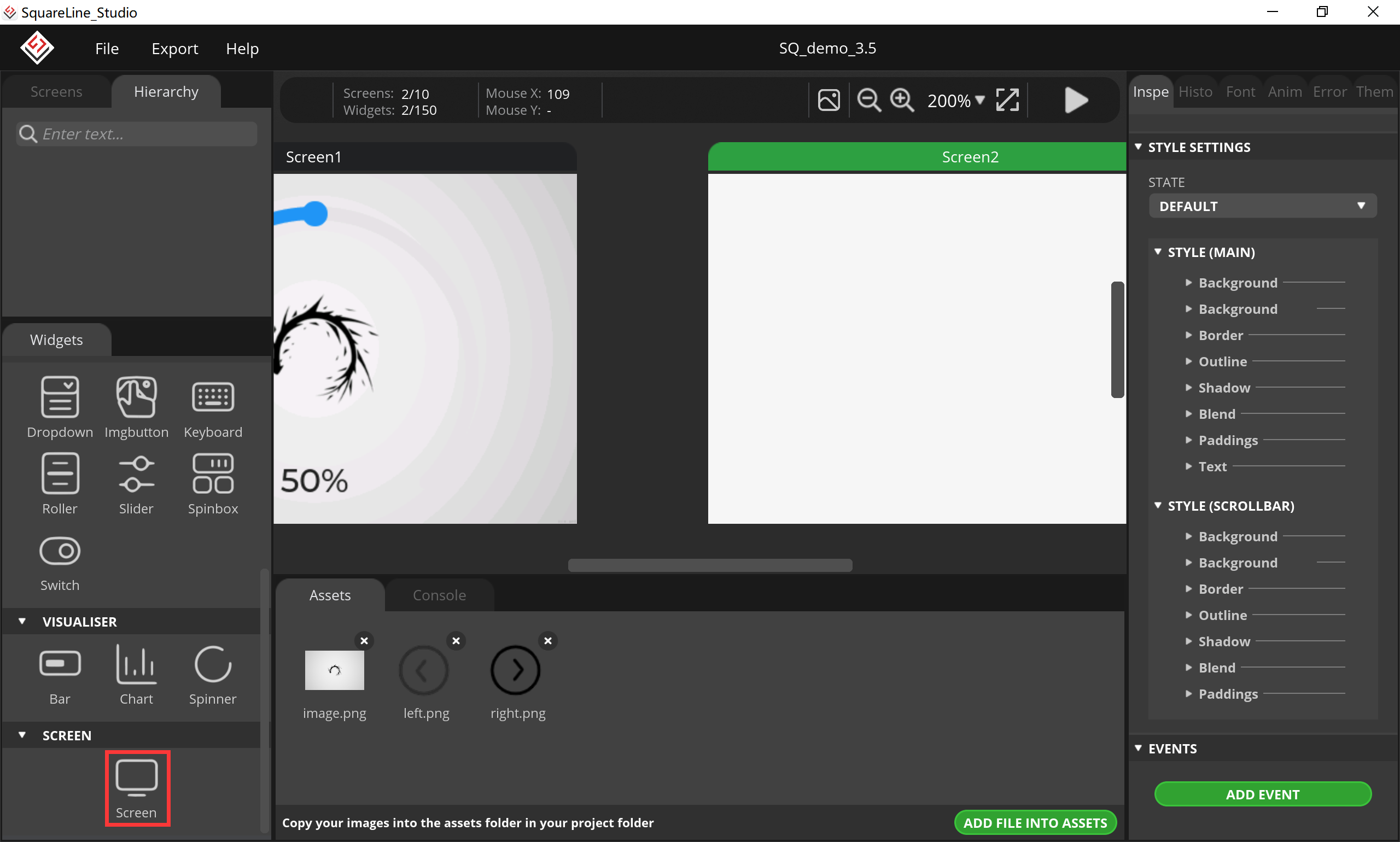
8.Add a Screen.
9.Add a textarea.
- Click “Textarea”, set its size and position.
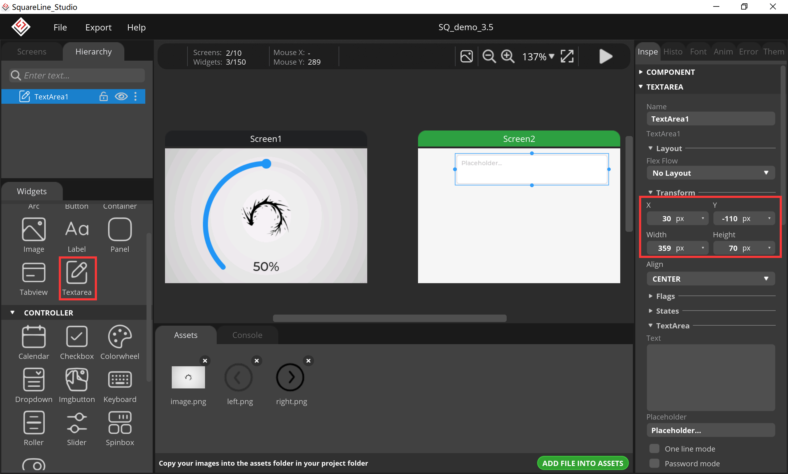
10.Add a keyboard, set textarea value from keyboard.
- Click “Keyboard”, set its size and position, the target textarea select “TextArea1”.
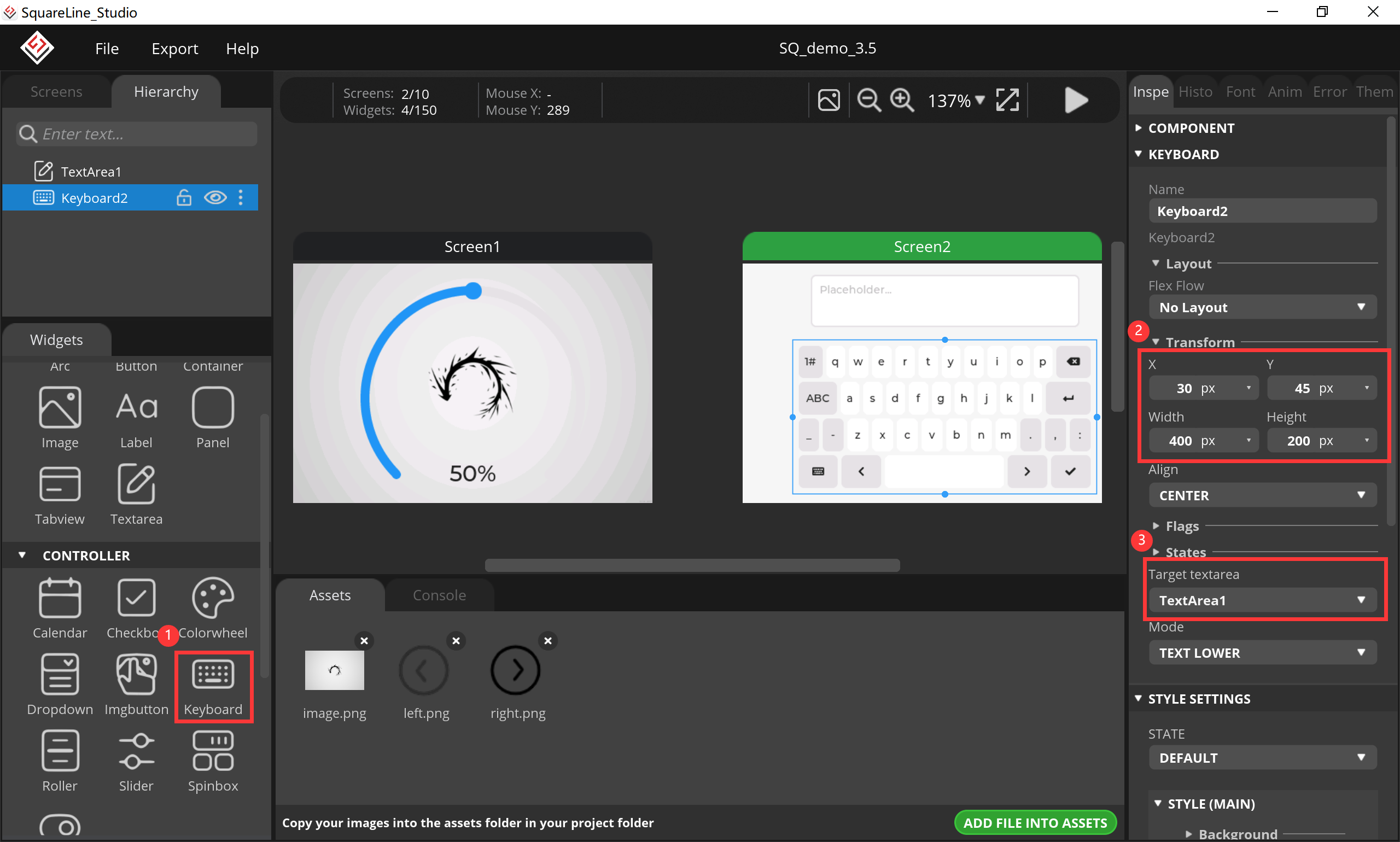
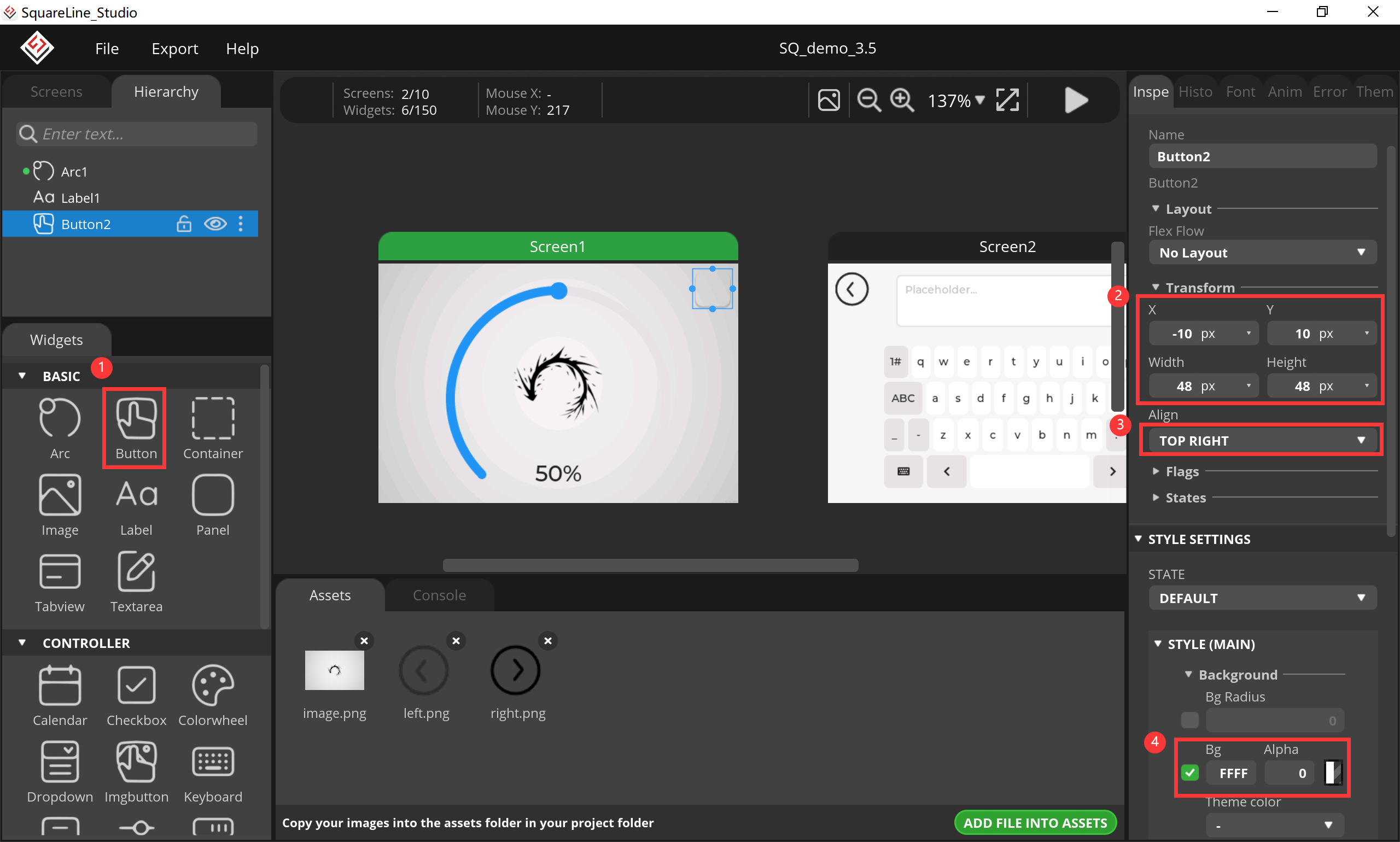
11.Add button for screen switching.
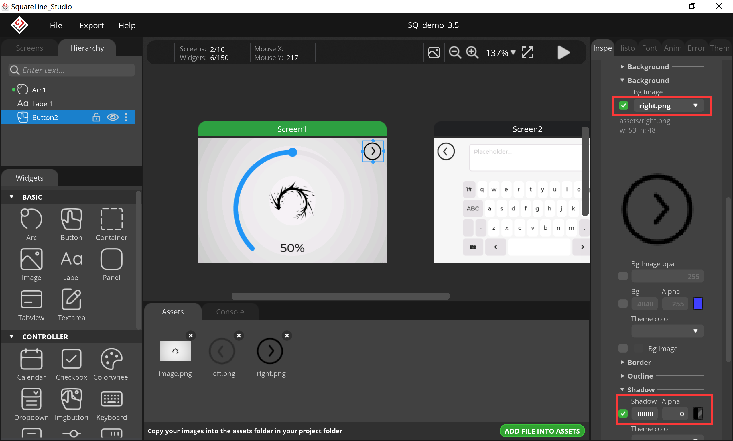
- Click “Button”, set its size and position, change its background.
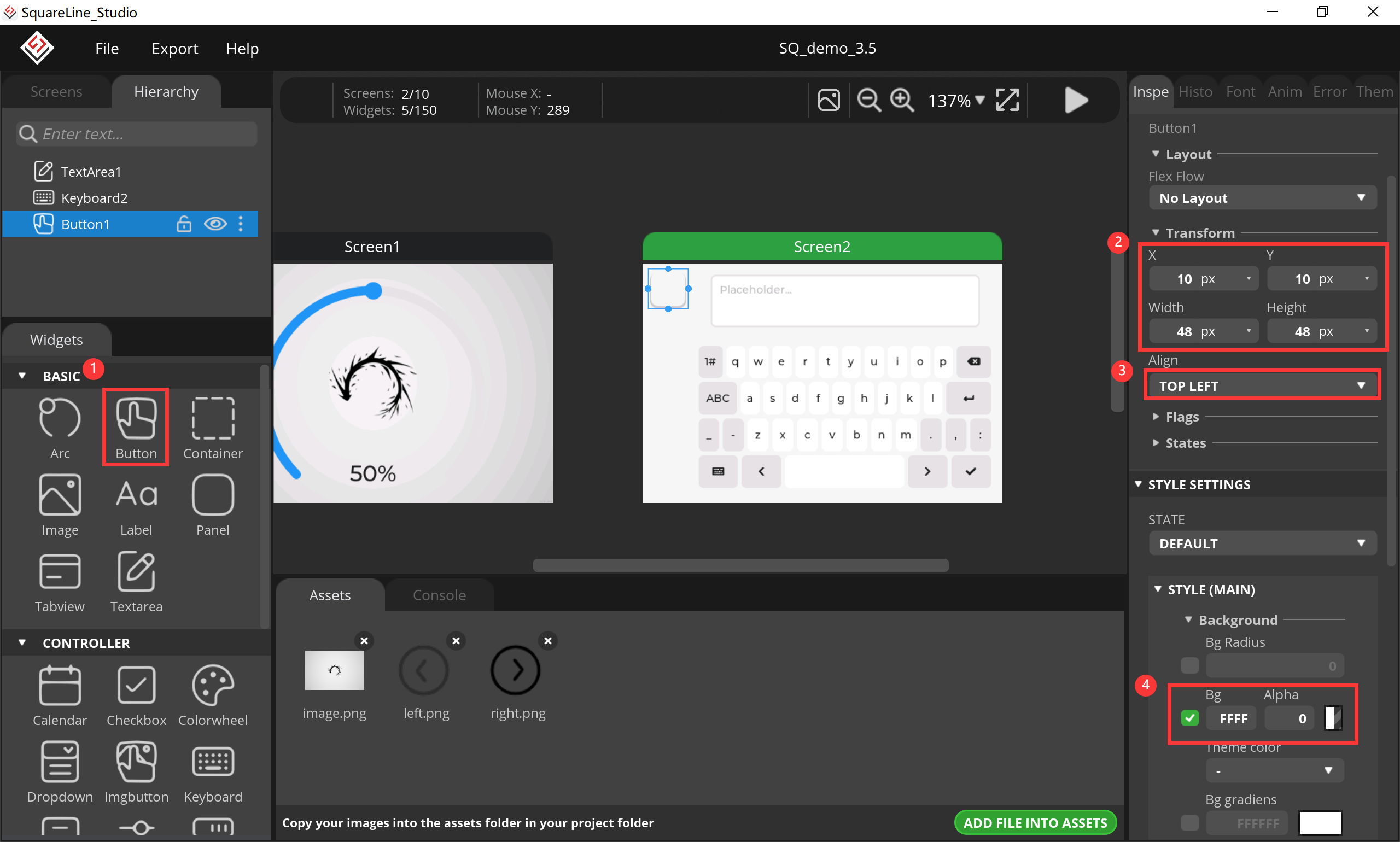
- change its background image and shadow.
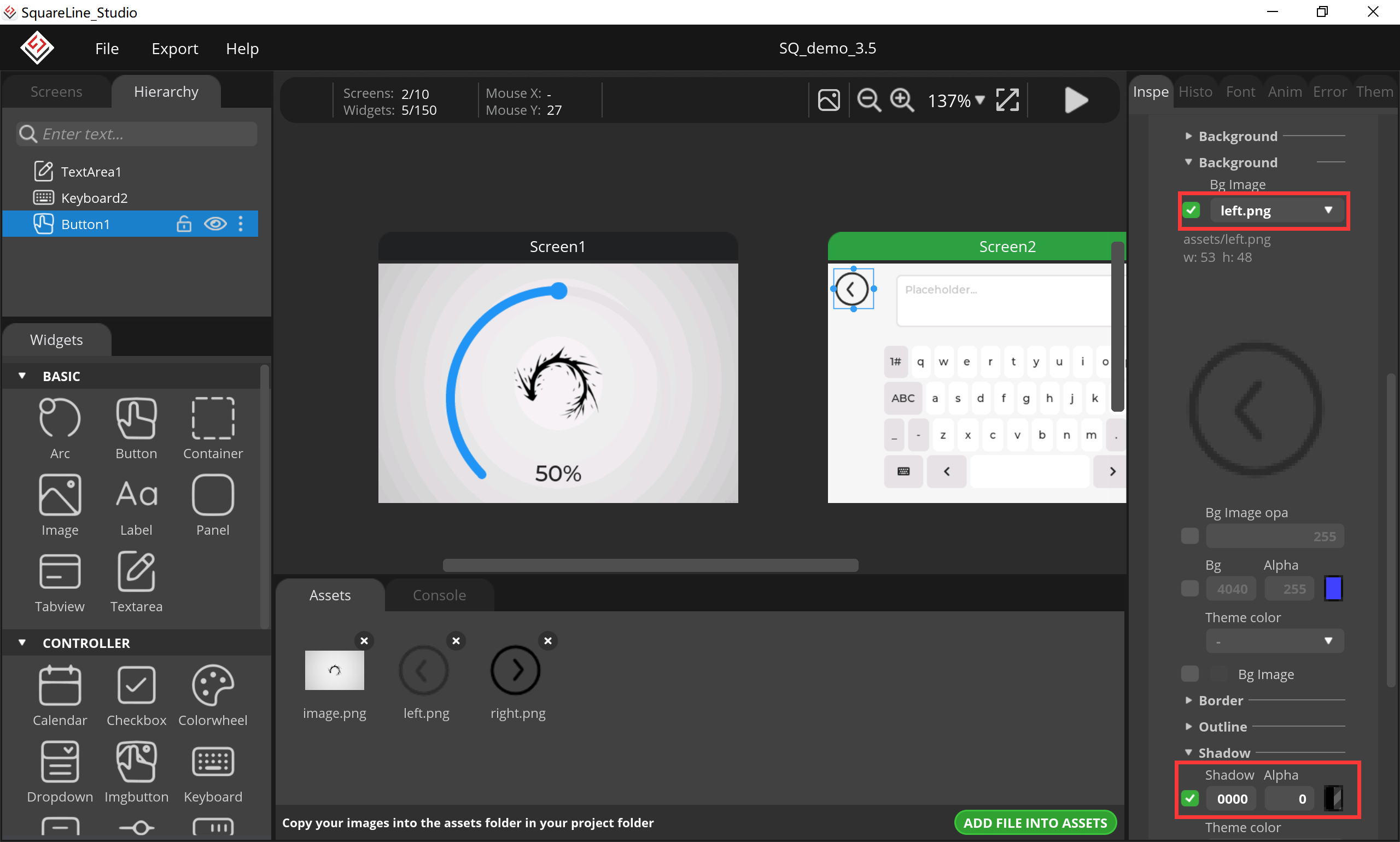
- Click “Screen1”, add a button as the same way with screen2.
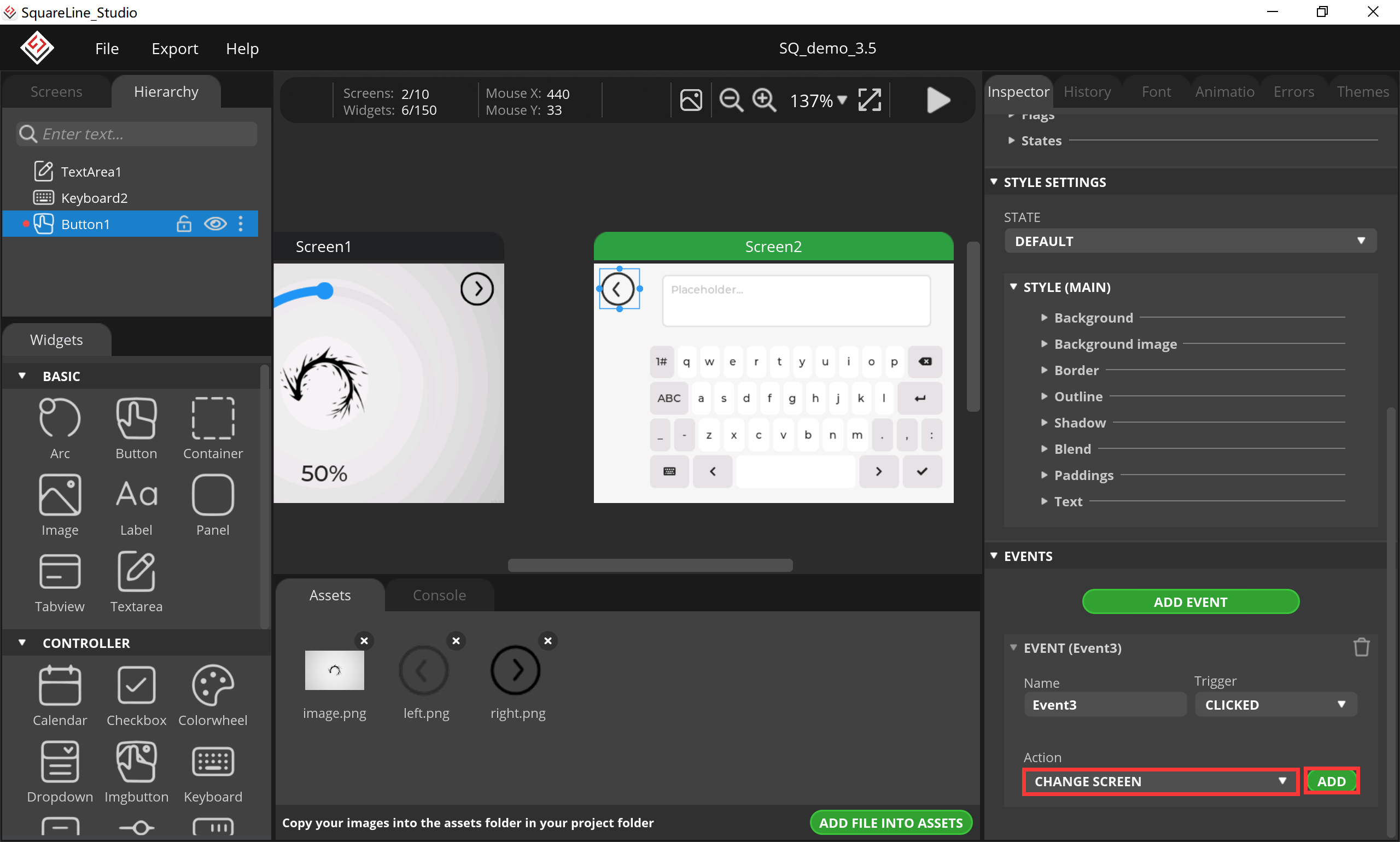
12.Add an event for screen switching.
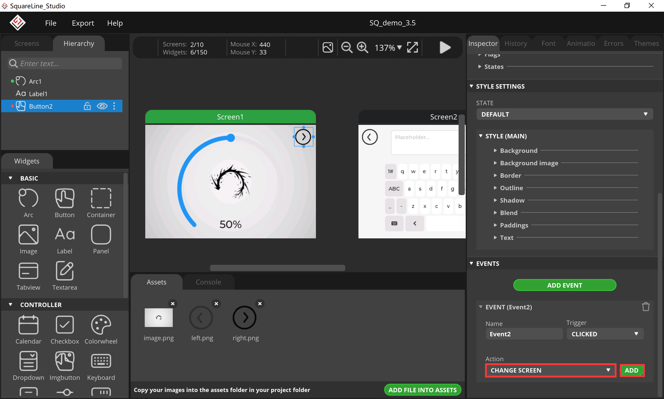
- Click “button2”, select “CHANGE SCREEN” and click “ADD”.
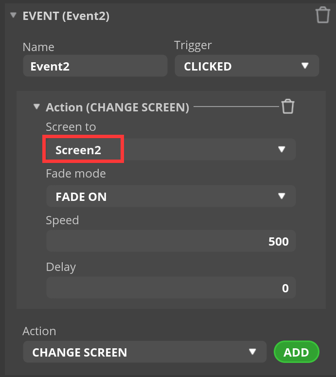
- Select “Screen2”.
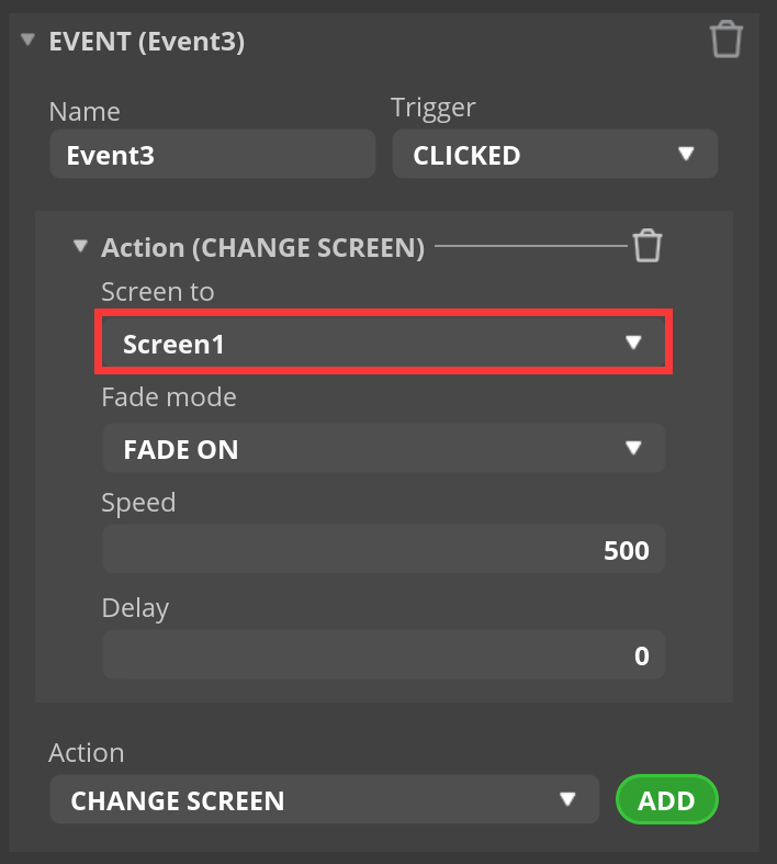
- Click “button1”, select “CHANGE SCREEN” and click “ADD”.
- Select “Screen1”.
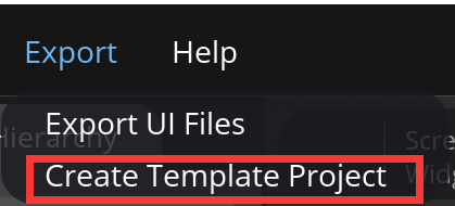
13.Export project.
- Click “Export-->Create Template Project”.
- Export the project file to the location you want.

- Wait for export succeed.

6.2 Code Upload with Arduino IDE
This projects are based on ESP32-S3 development board. If you didn't install the ESP32 Board SDK, you can follow this guide to learn how to do it.
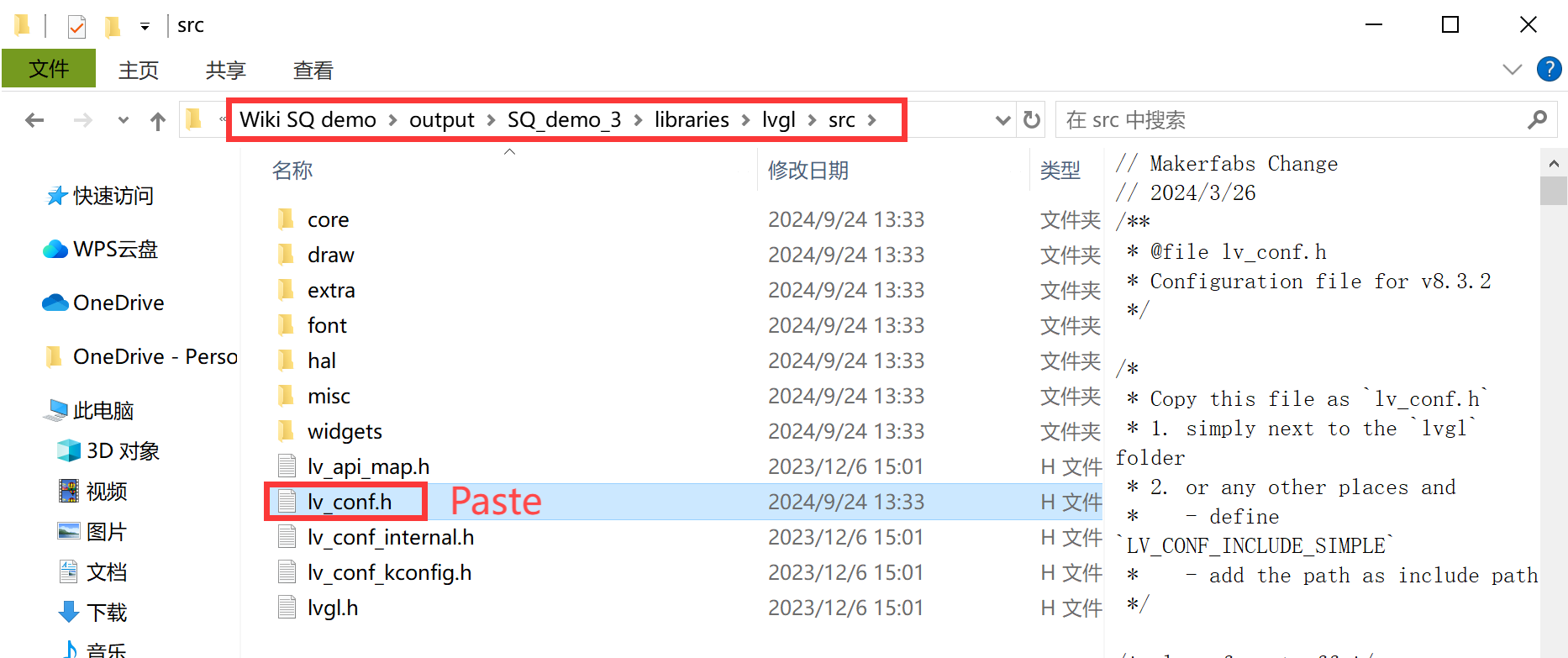
1.Click on the code project document you just export.
- Copy the “lv_conf.h” into the “src” in the lvgl in libraries.

- Copy these files into the Arduino library.


- Open the ui.ino.

- Before uploading the sketch, select and set the parameter in the Tools menu, as picture:
6.3 Result
7. FAQ
You can list your question here or contact techsupport@makerfabs.com for technology support. Detailed descriptions of your question will be helped to solve your question.
Q1: Why the display fails to respond sometimes I touch?
A1: The touching interface is loose, please reconnect it.
Q2: What is the difference between hardware v1.0 and v2.0?
A2: Here are the modify key points of hardware v2.0:
-
1.Replace the ESP32-S3-WROOM-N16R8 module.
-
2.LCD_WR is changed from IO35 to IO18.
-
3.LCD_RS is changed from IO36 to IO17.
-
4.LCD_CS is changed from IO37 to IO46.
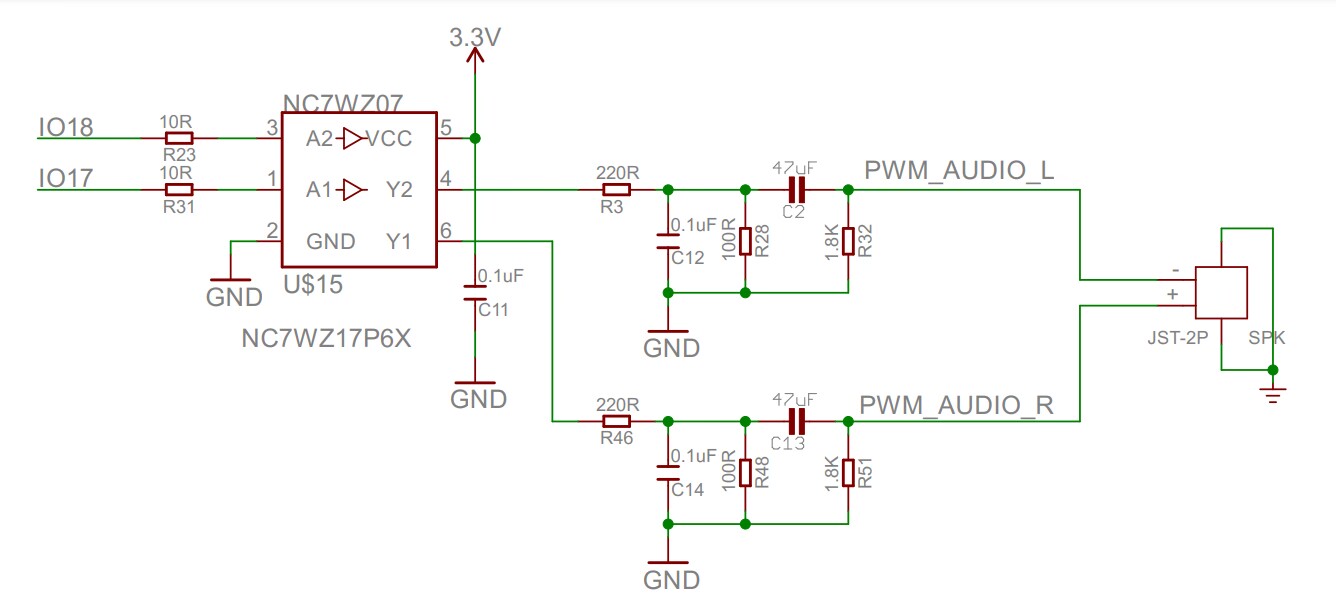
- 5.The Mabee interface pin is changed from IO17/IO18 to IO19/IO20.
