ESP32-S3 Parallel 4.0" TFT with Touch
1. Introduction
ESP32-S3 Parallel 4.0 TFT with Touch is a new solution for IoT application, Choose the ESP32-S3, whicn is a execllent performance controllter. Compare with ESP32-S3 4.3 inch IPS display it increase the I2S output. In many IoT scenarios, Audio playing can have a better exhibition effect. by integrating display/ touch/ audio speaker/ Lipo charger, to make this product ideal for applications such as IoT controlling, electronic photo frame, etc.
Module:E32S3RGB40
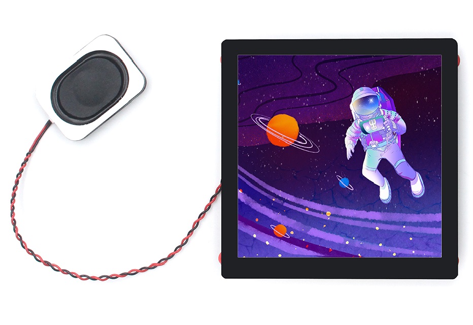
2. Feature
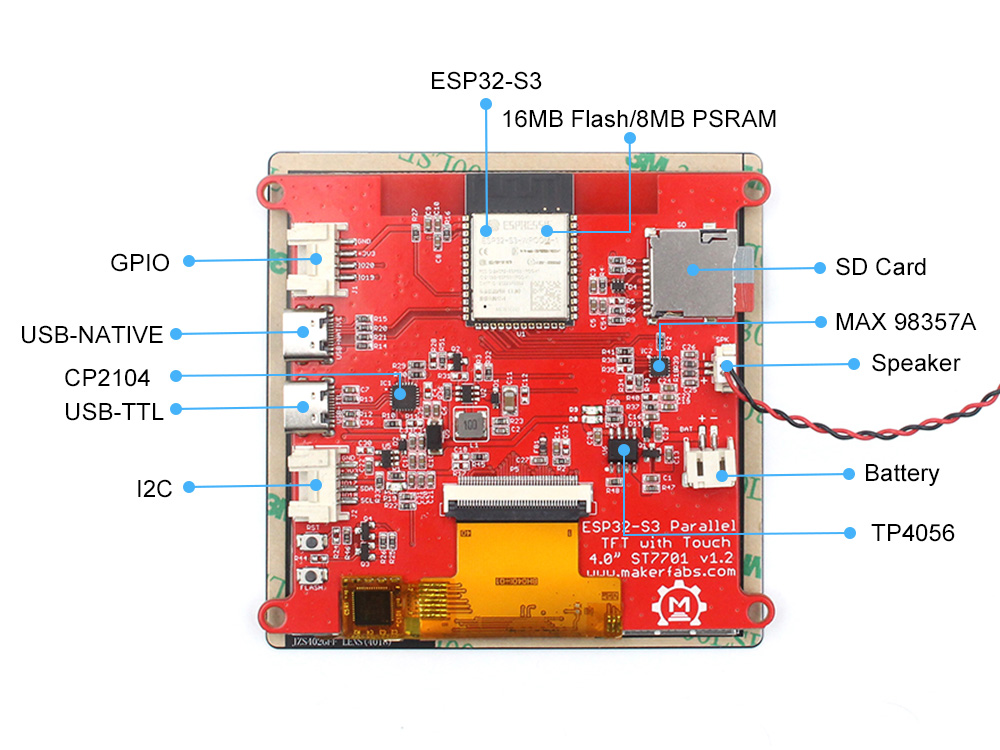
- Controller: ESP32-S3-WROOM-1, PCB Antenna, 16MB Flash, 8MB PSRAM,
- Wireless: Wifi& Bluetooth 5.0
- LCD: 4.0 inch High Lightness IPS
- FPS: >50
- Resolution: 480*480
- LCD interface: RGB565 +3-wire SPI
- LCD Driver: ST7701S
- USB: Dual USB Type-C(one for USB-to-UART and one for native USB)
- Touch Panel: 5 Points Touch, Capacitive
- Touch Panel Driver: GT911
- USB to UART Chip: CP2104
- Power Supply: USB Type-C 5.0V(4.0V~5.25V)
- Button: Flash button and reset button
- Mabee interface: 1 * I2C; 1 * GPIO
- MicroSD: Yes
- Type-C Power Delivery: Not Supported
- Operation temperature: -40℃ to +85℃
- Speaker(I2S)
- Lipo battery charger& connector
- Audio: MAX98357A
3. Usage in Arduino IDE
If you need backlight control, you need to solder R28 whose resistance is 1kΩ(the default is not soldered when leaving the factory), and remove the R29 resistor.
3.1 Software setup
Note that the same version of the libraries and packages are recommended in case of updates make unexpected results. All the projects are based on ESP32-S3. If you didn't install the ESP32 Board SDK, you can follow this tutorial to install it.
1.Install the TAMC_GT911 library V1.0.2.

- Install the GFX_Library_for_Arduino library V1.3.1.

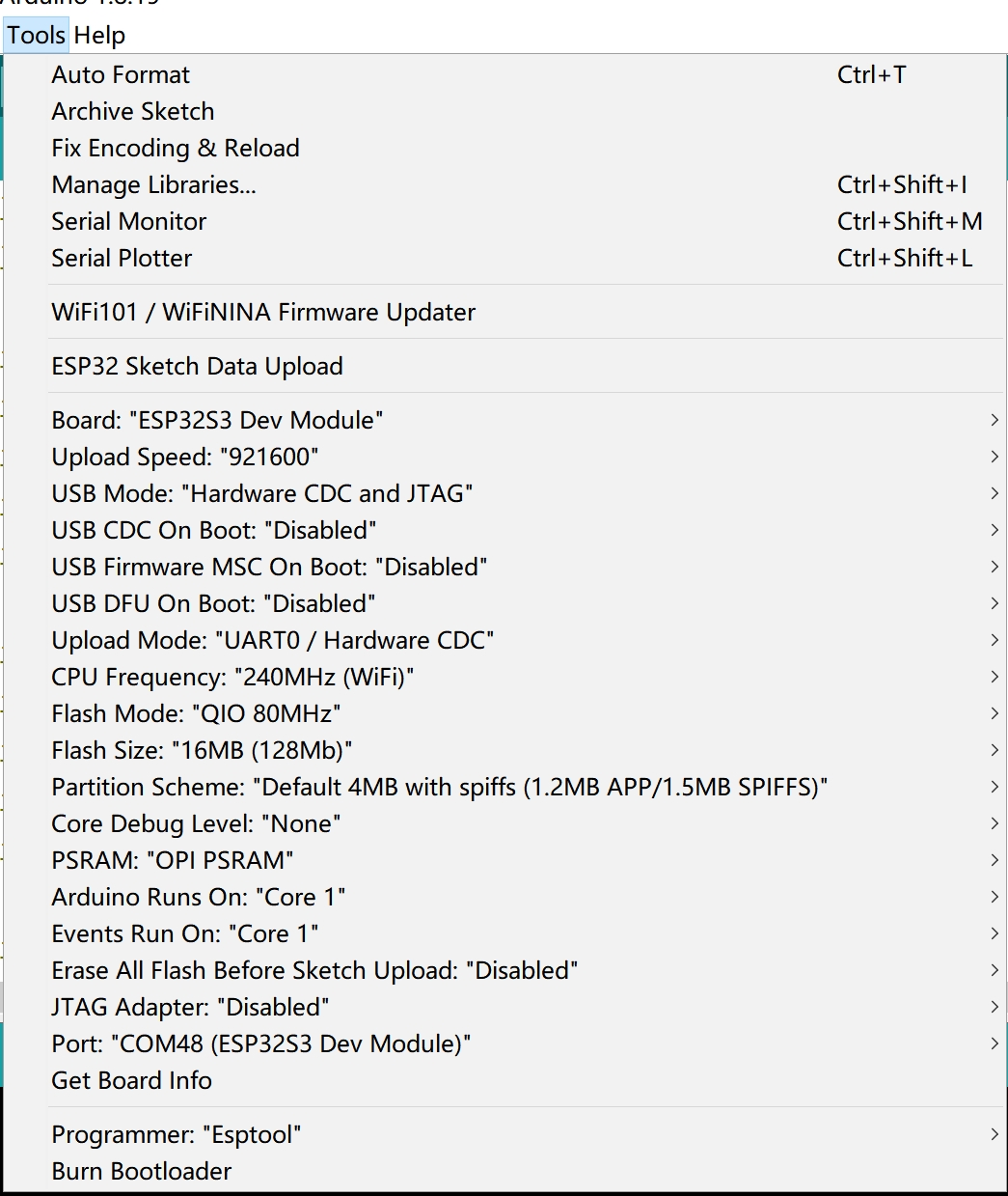
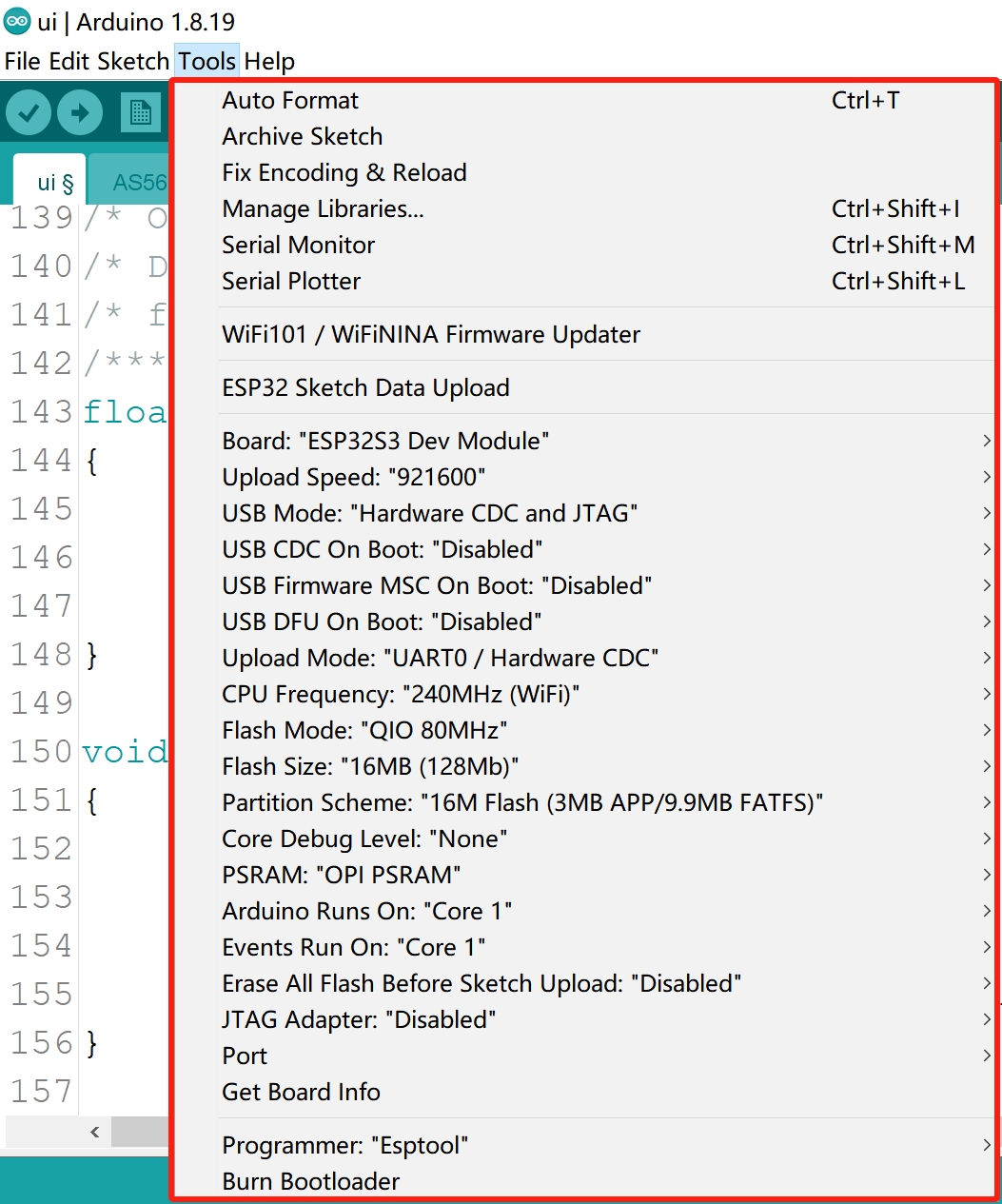
Select and set the parameter in the Tools menu before uploading the sketch,shows as below:
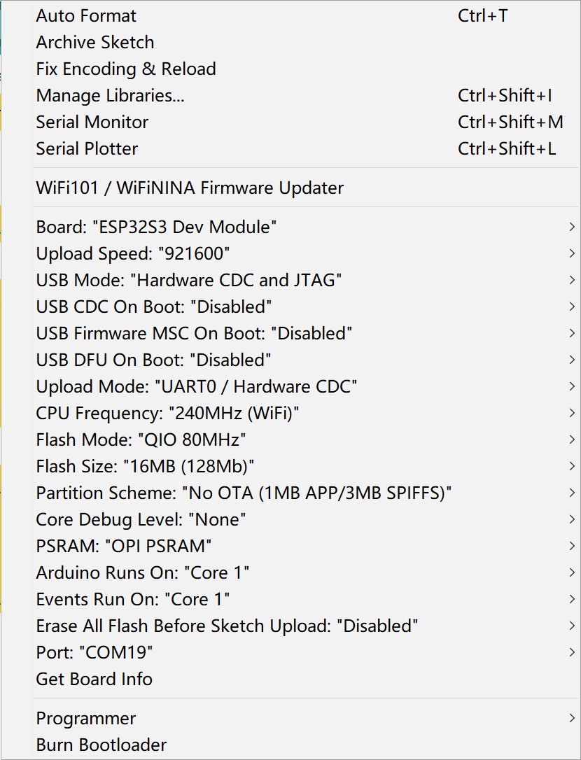
Note: Different PC has different Serial COM number, select your local serial number
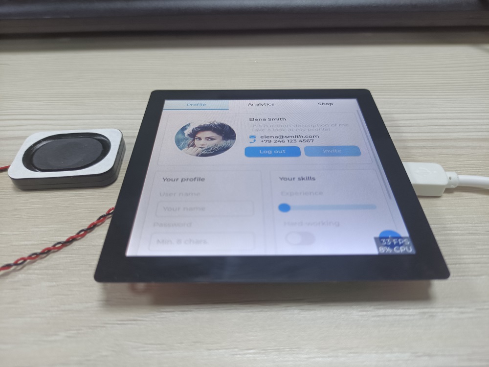
3.2 LVGL Demo
1.Download the MF_Lvgl library.
2.Click sketch-->include library--> ADD.ZIP library
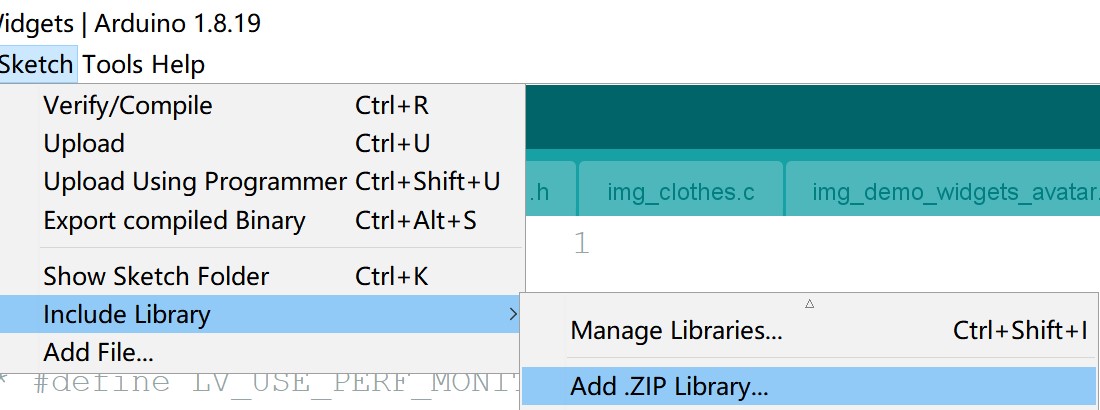
3.Choose the path of MF_Lvgl.
4.Download the SD_file and unzip it, copy these files to the microSD card.
5.Open the LvglWidgets by Arduino IDE.
6.Verify and upload the sketch.
The version of the libraries shows as below. It may cause compilation errors if you use different version of the libraries!

3.3 PDQgraphics demo
Open the PDQgraphicstest by Arduino IDE.
Verify and upload the code. it will display as follows.
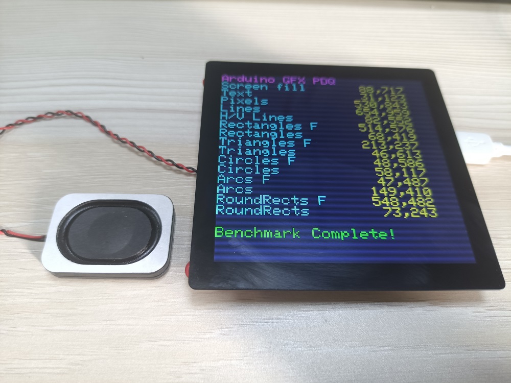
If you want to know more display effects with ESP32-S3 Parallel 4.0 TFT with Touch, watch the following video.
3.4 Bightness control Demo
Notice: Before you can implement this demo, you must solder R28 whose resistance is 1kΩ(the default is not soldered when leaving the factory), and remove the R29 resistor.
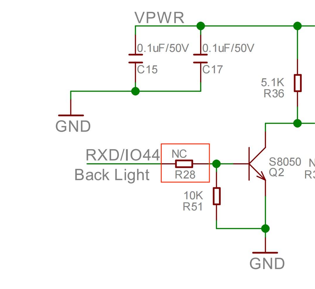
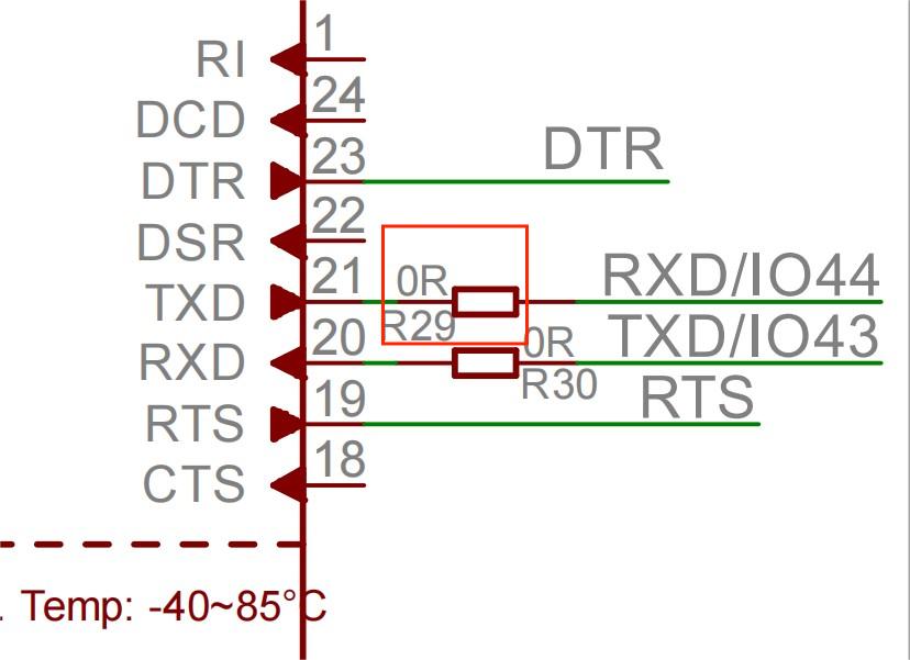
Open Bightness control Demo by Arduino IDE.
Use Type-C USB cable to connect the board and PC, note plug the cable to USB-NATIVE interface, and select the development board "ESP32S3 Dev Module" and the port.
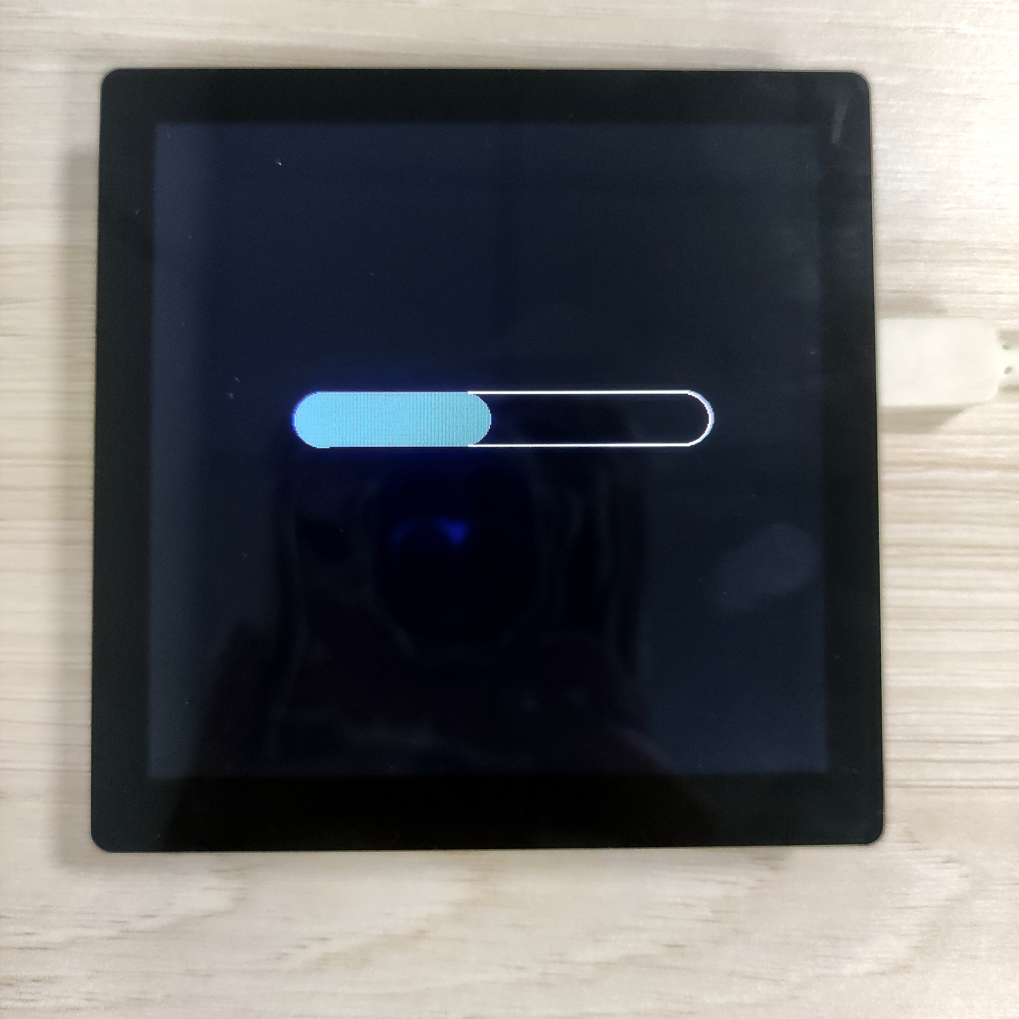
Verify and upload the code. it will display as follows.
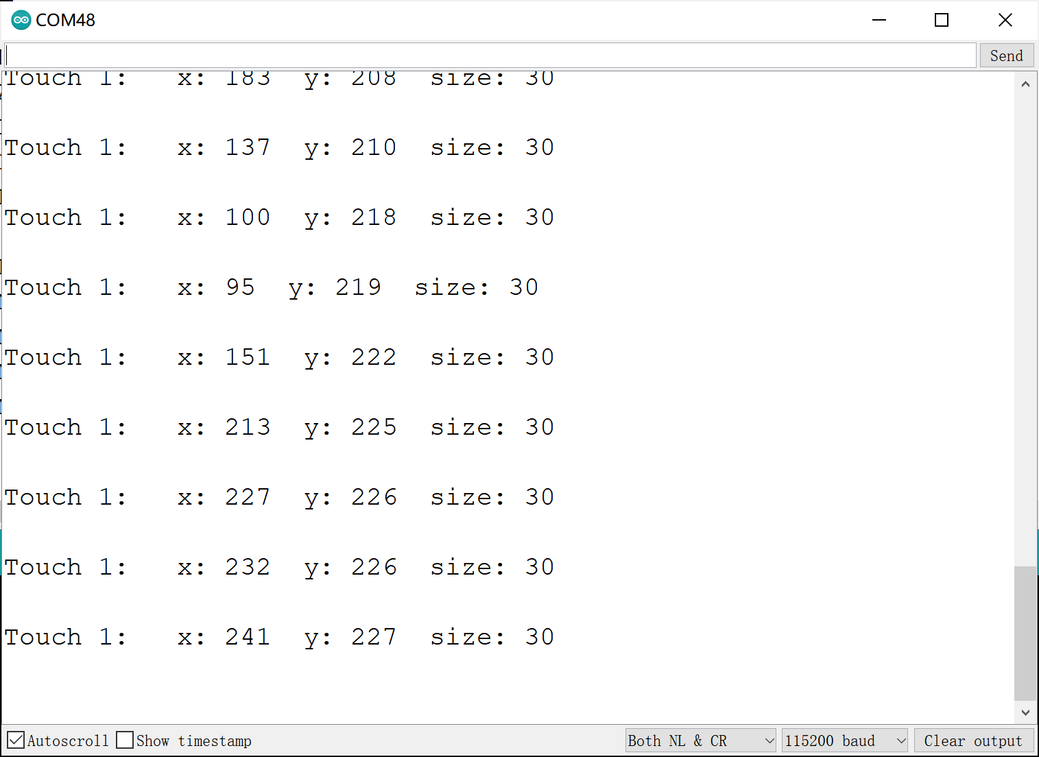
Swipe the progress bar and you will see the brightness of the screen change and you can open the Serial Monitor to capture the coordinates of the screen points.
4. Usage in VS Code & PlatformIO
Downloaded and installed PlatformIO IDE for VSCode
4.1 LVGL Demo
Download and unzip the LvglWidgets, open this project by VS Code.
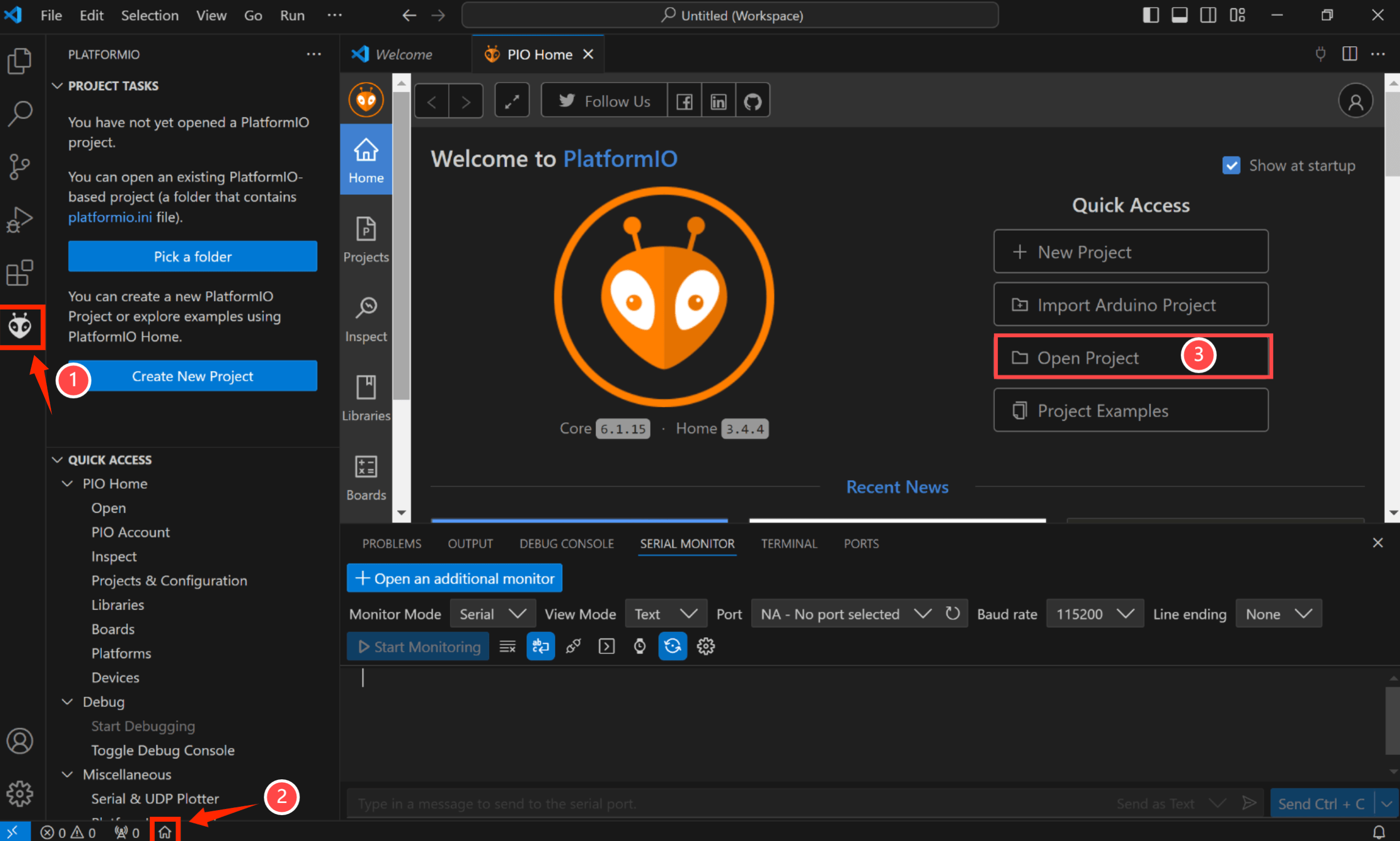
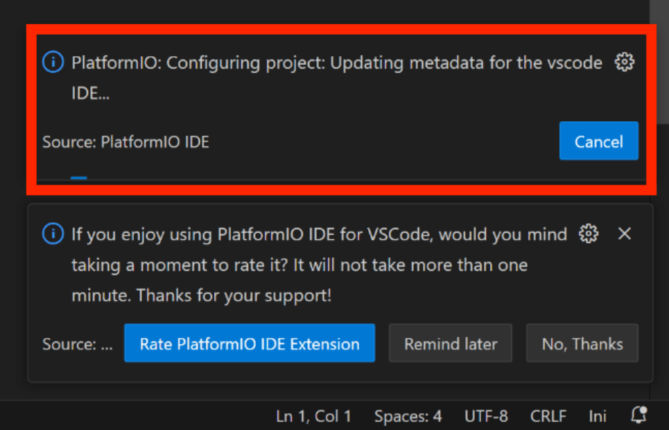
Waiting for configuration project.
- Click "src-->main.cpp".
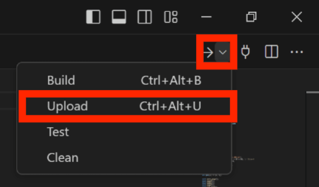
Verify it and upload.
Result

4.2 PDQgraphics demo
Download and unzip the PDQgraphicstest, open this project by VS Code.

Waiting for configuration project.

- Click "src-->main.cpp".
Verify it and upload.

Result

4.3 Bightness control Demo
Download and unzip the Bightness control, open this project by VS Code.

Waiting for configuration project.

- Click "src-->main.cpp".
Verify it and upload.

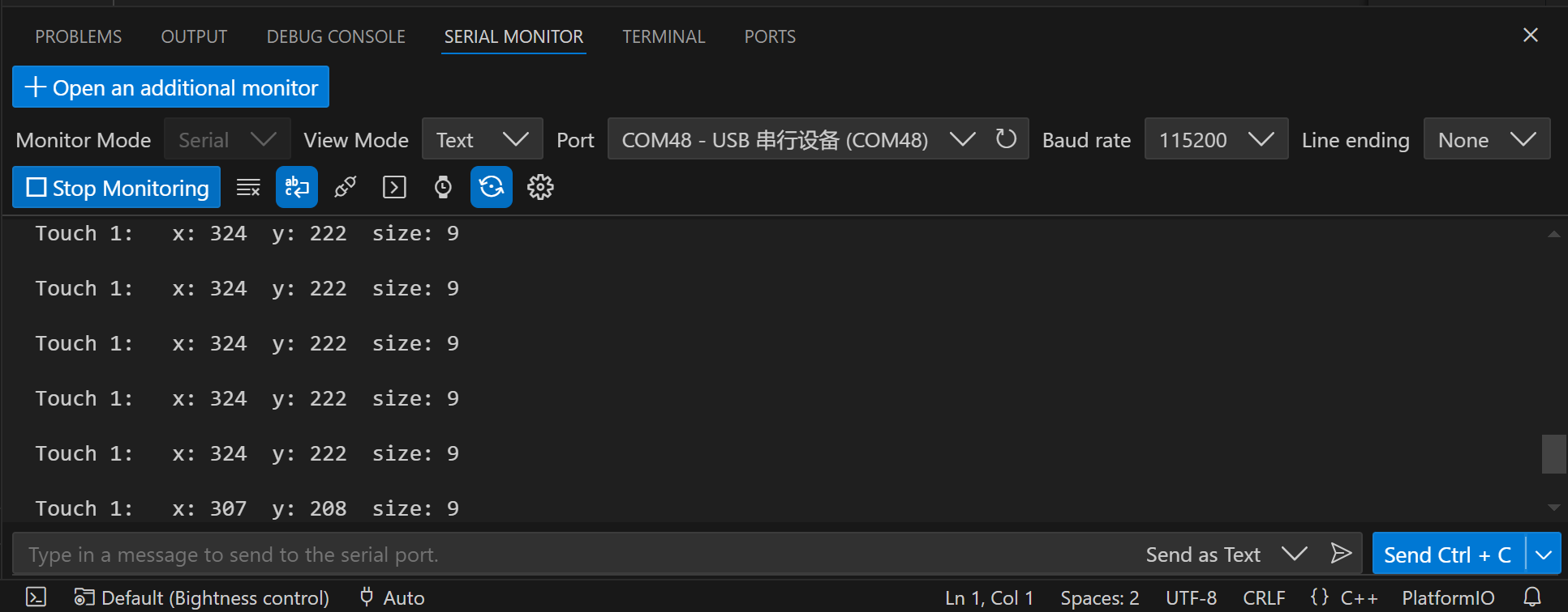
Result:Swipe the progress bar and you will see the brightness of the screen change and you can open the Serial Monitor to capture the coordinates of the screen points.

5. Usage in SquareLine Studio
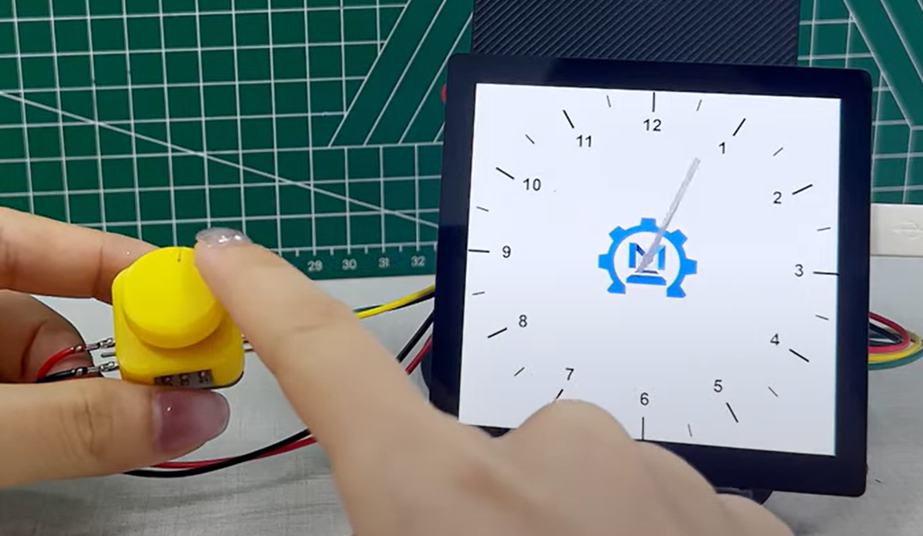
We cleverly combined the AS5600 module, 3D printing technology, Squareline ui design and Arduino programming to create a smart magnetic knob. The AS5600 module accurately captures the rotation Angle to provide high-precision feedback for the knob; 3D printing gives the knob its unique shape and durability. Design your favorite ui on Squareline and interact with MaTouch through Arduino.
For the use of SquareLine you can refer to this video. LVGL Usage with Squareline & MaTouch Lesson #3
For the use of code you can find in Github
5.1 Hardware preparation
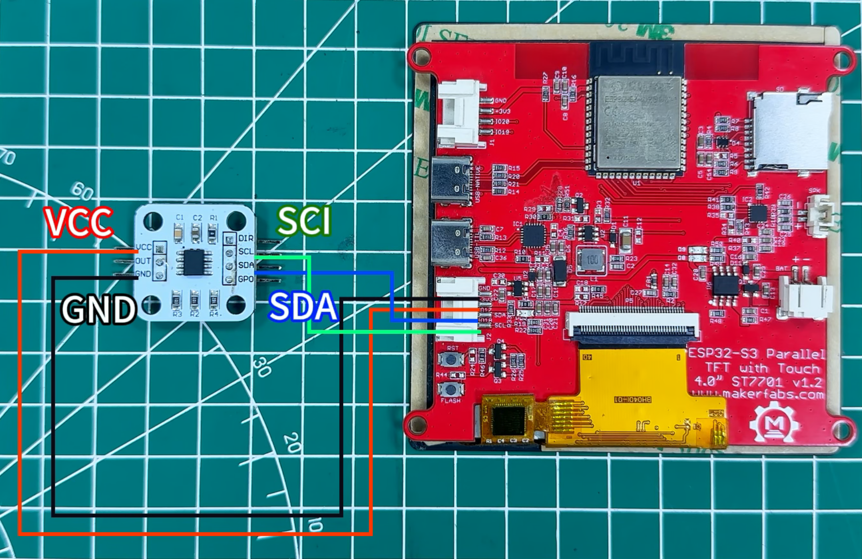
1.Firstly, you need a AS5600 module, a magnet, a Bearing and a 3Dprinted case, and assemble them.
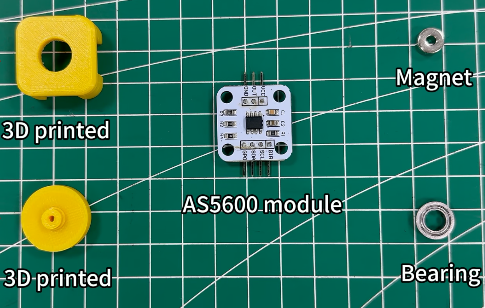
2.The AS5600 uses I2C port for communication with controller, connected it to Matouch 4irch display.
5.2 LVGL design with SquareLine Studio
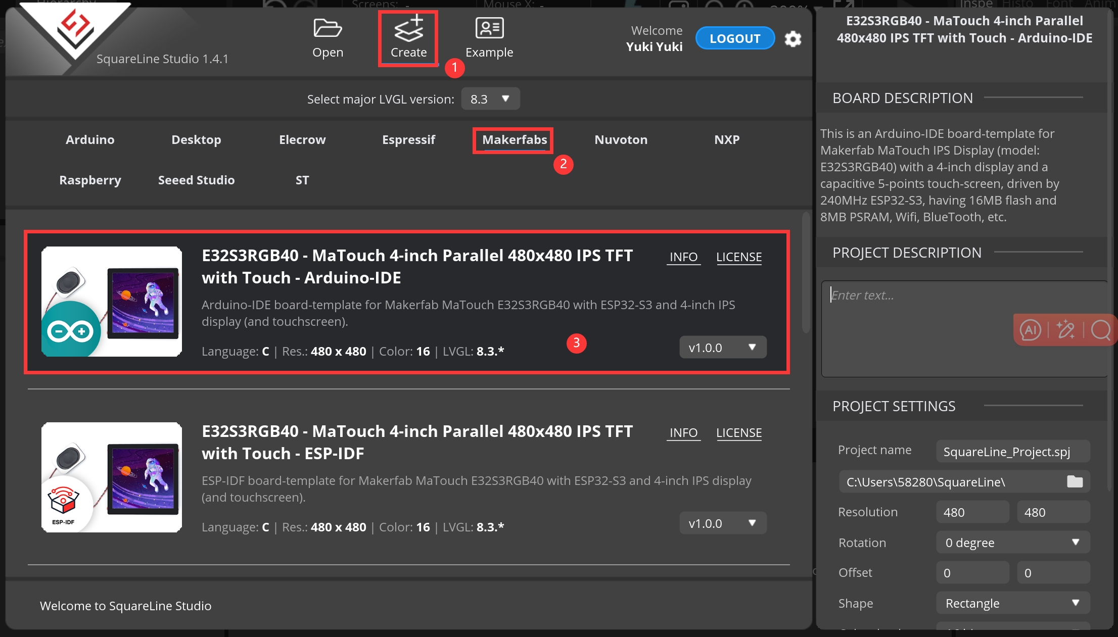
1.click on "Create-->Makerfabs", select the 4 inch screen
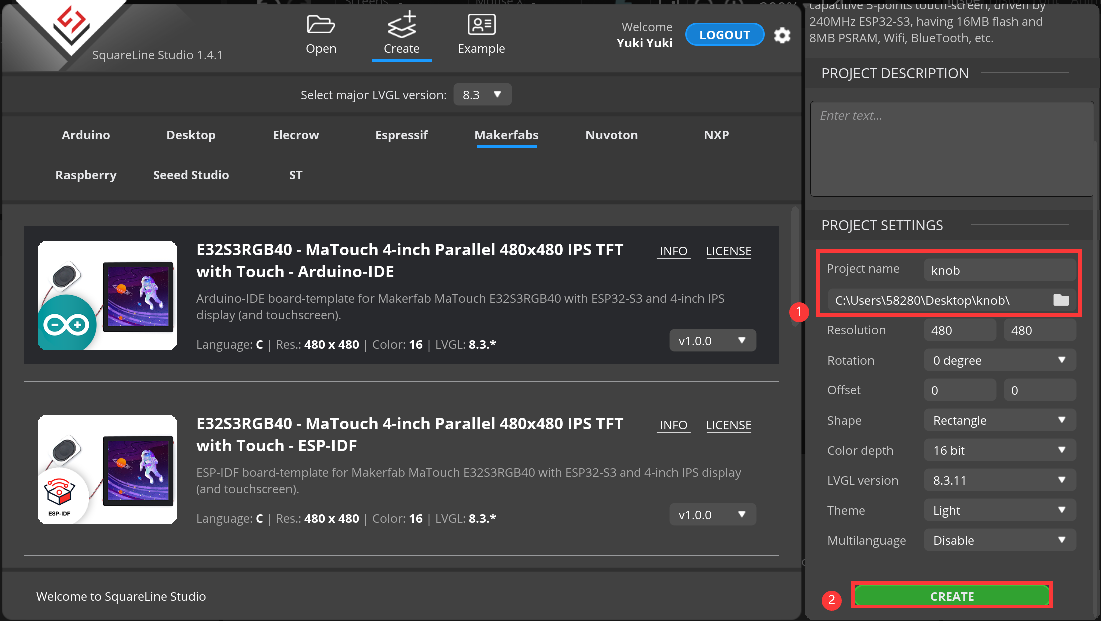
2.Modify the desired project name and location information, and then click “CREATE”.
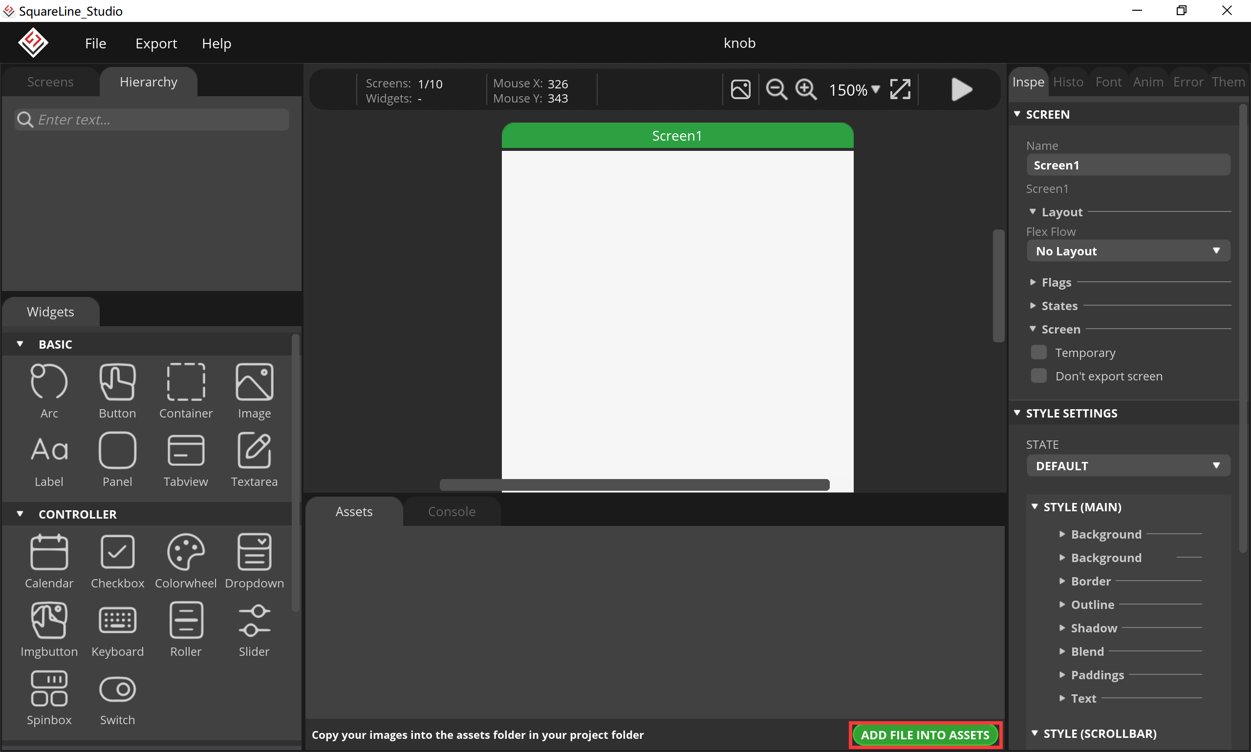
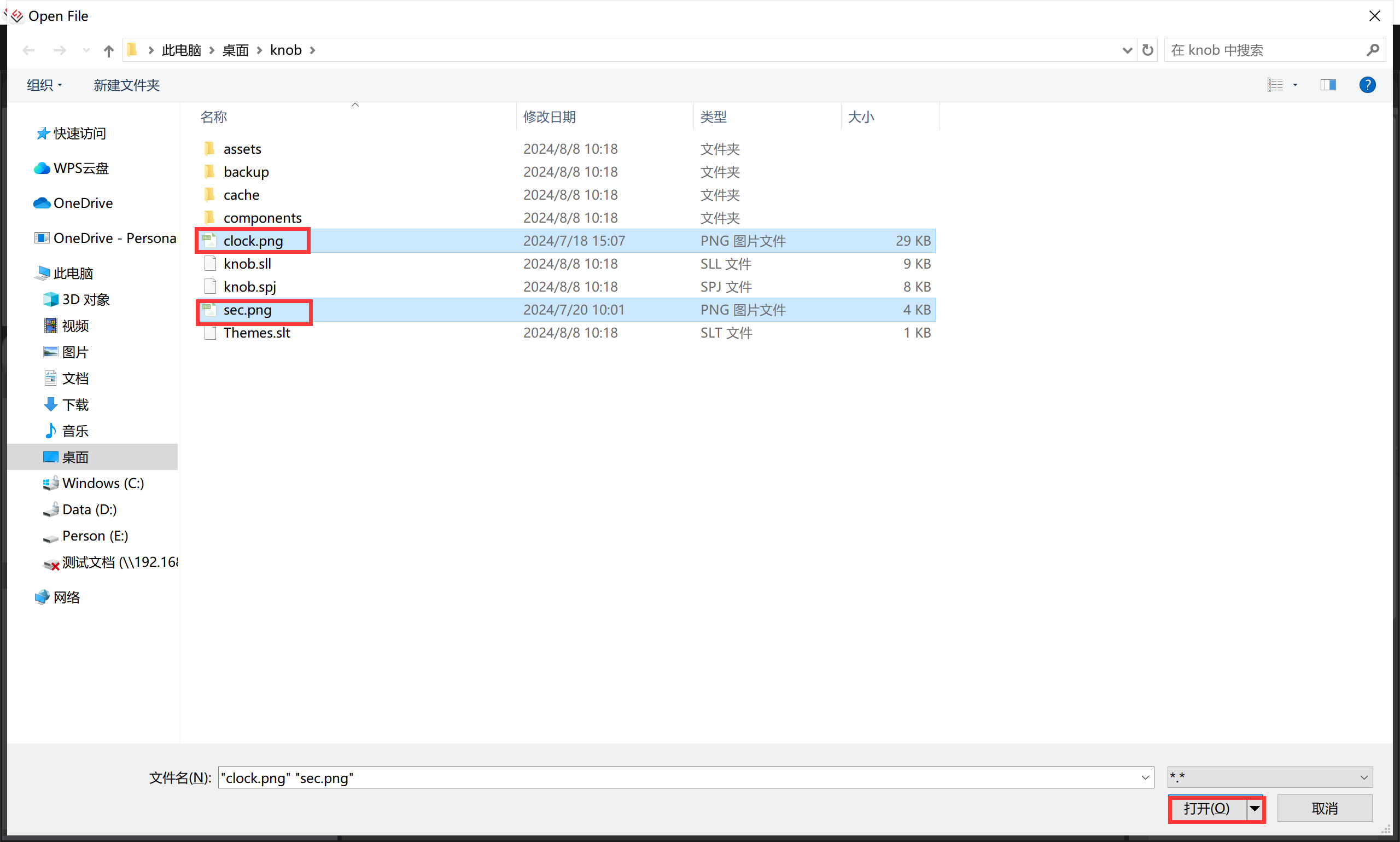
3.Add the image we need to use, click “ADD FILE INTO ASSETS”.
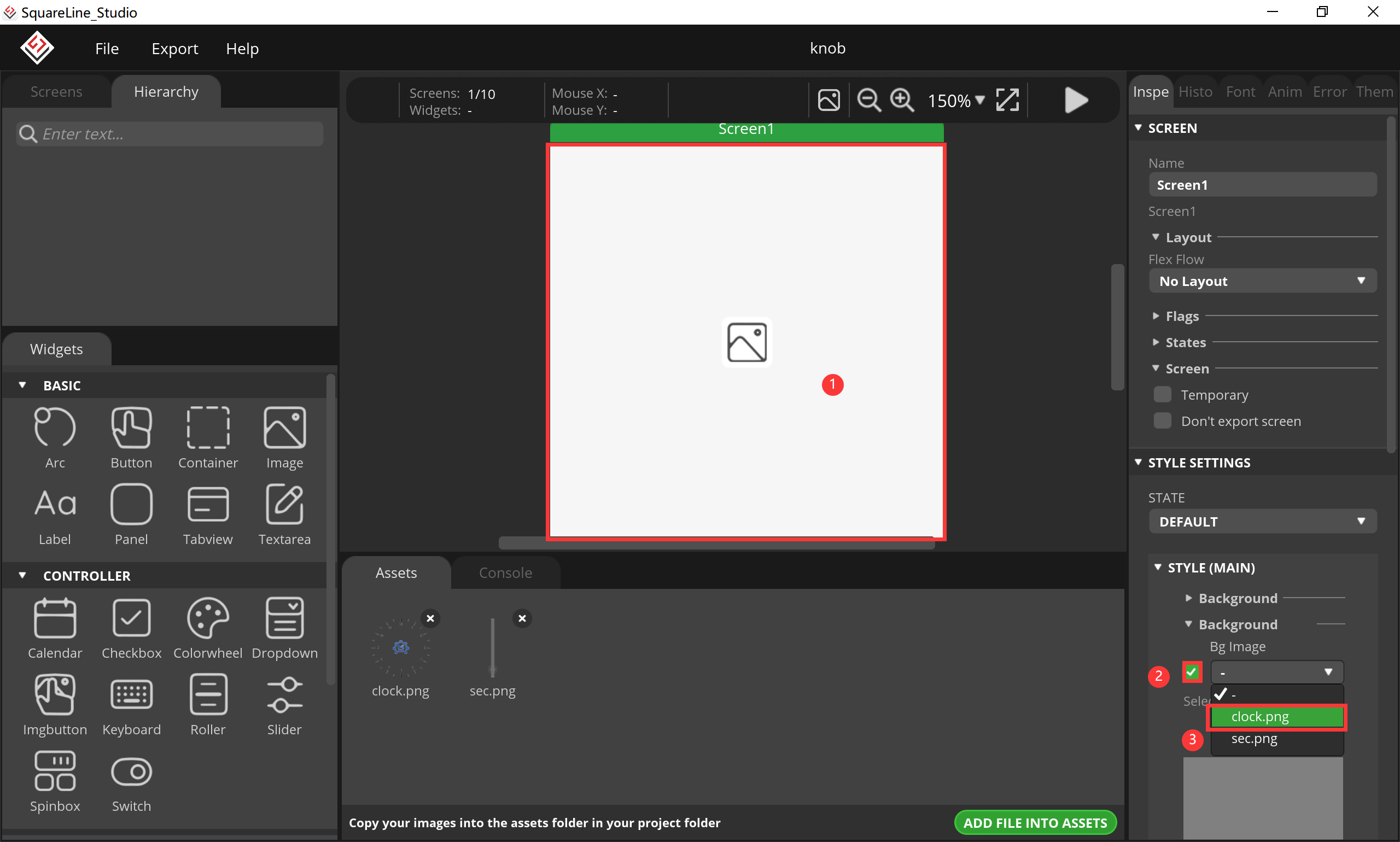
4.click screen, switch to the screen Settings, click "brackground", add the image to the screen.
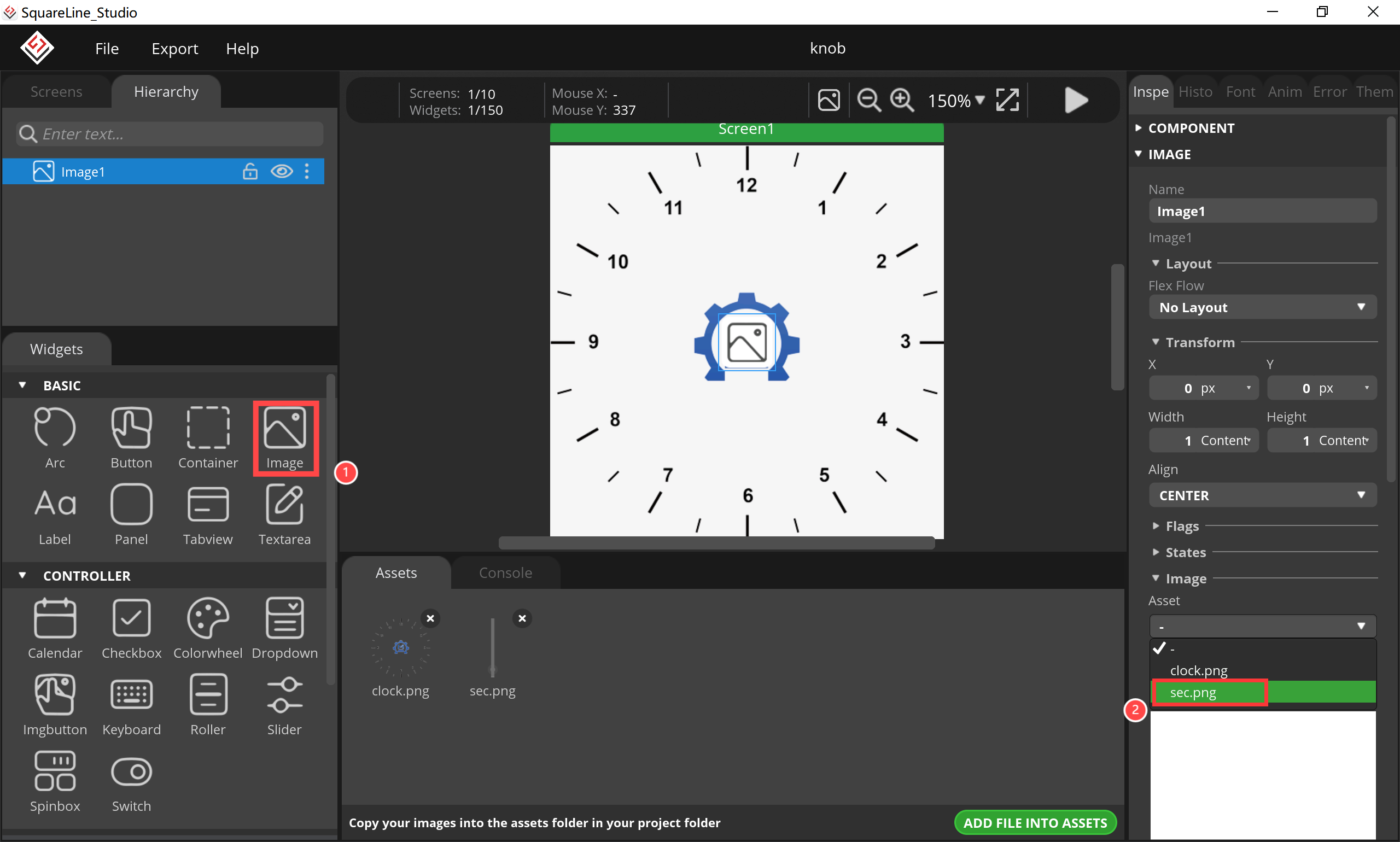
5.Add a image, change it brackground to set it to a knob.
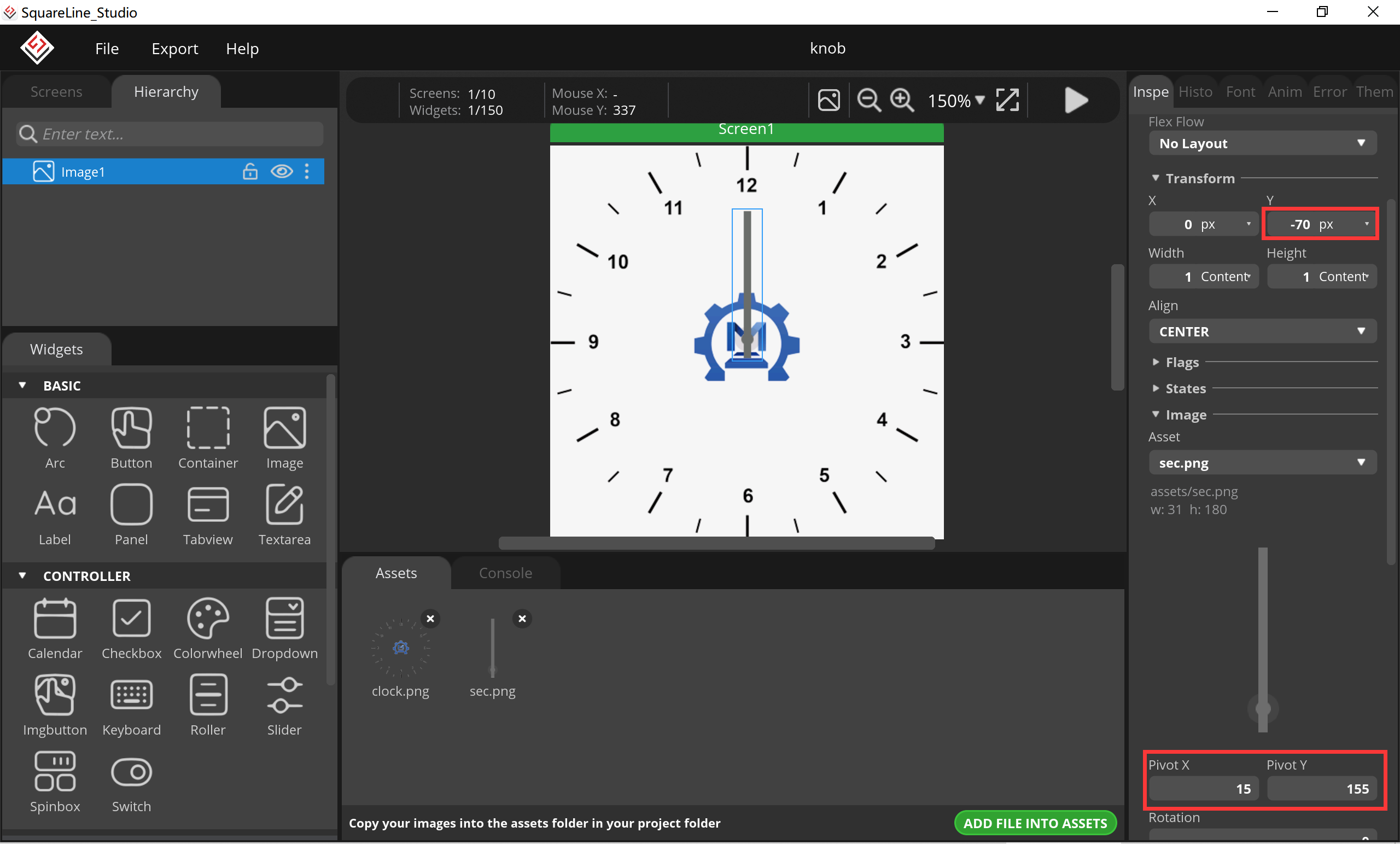
6.Change its position and rotation point.
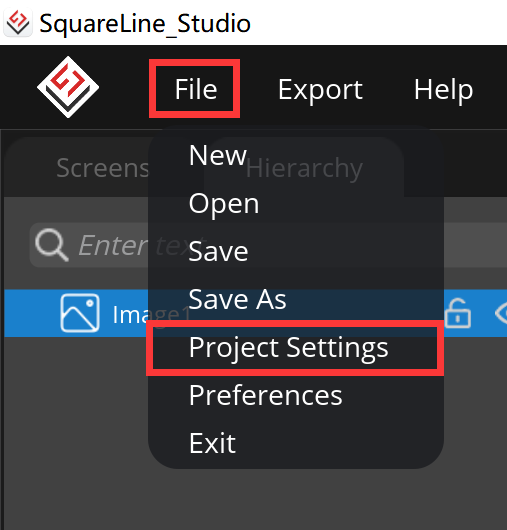
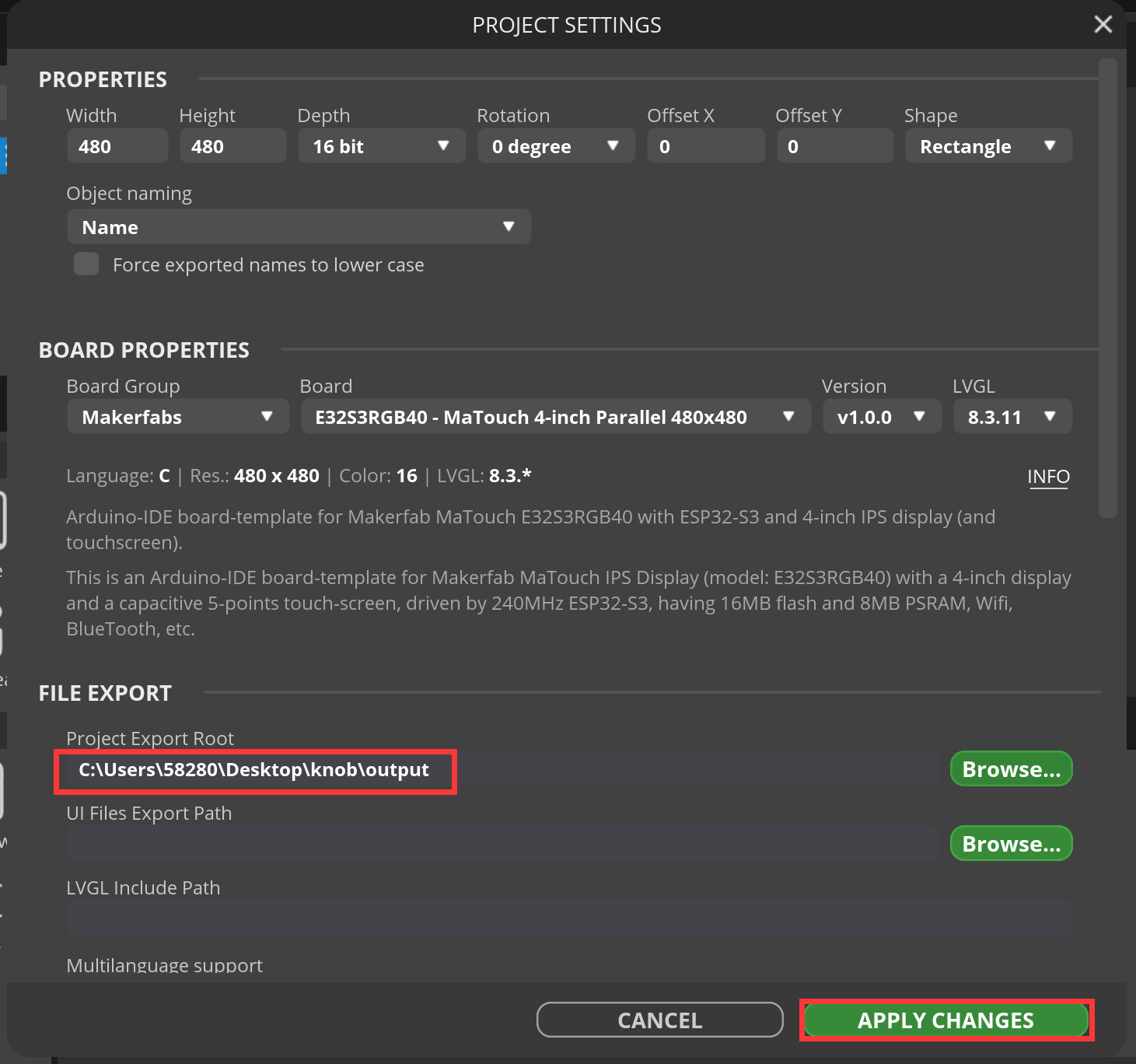
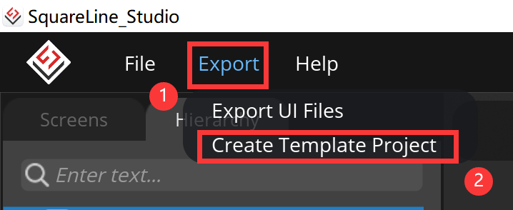
7.At this point, our LVGL graphical user interface has been designed. Click "ctrl s" to save, and then output the project code document.
5.3 Code Upload with Arduino IDE
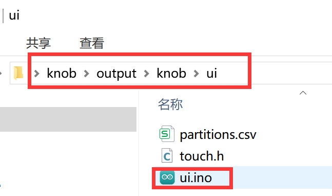
1.Open the output code file into the Arduino design.
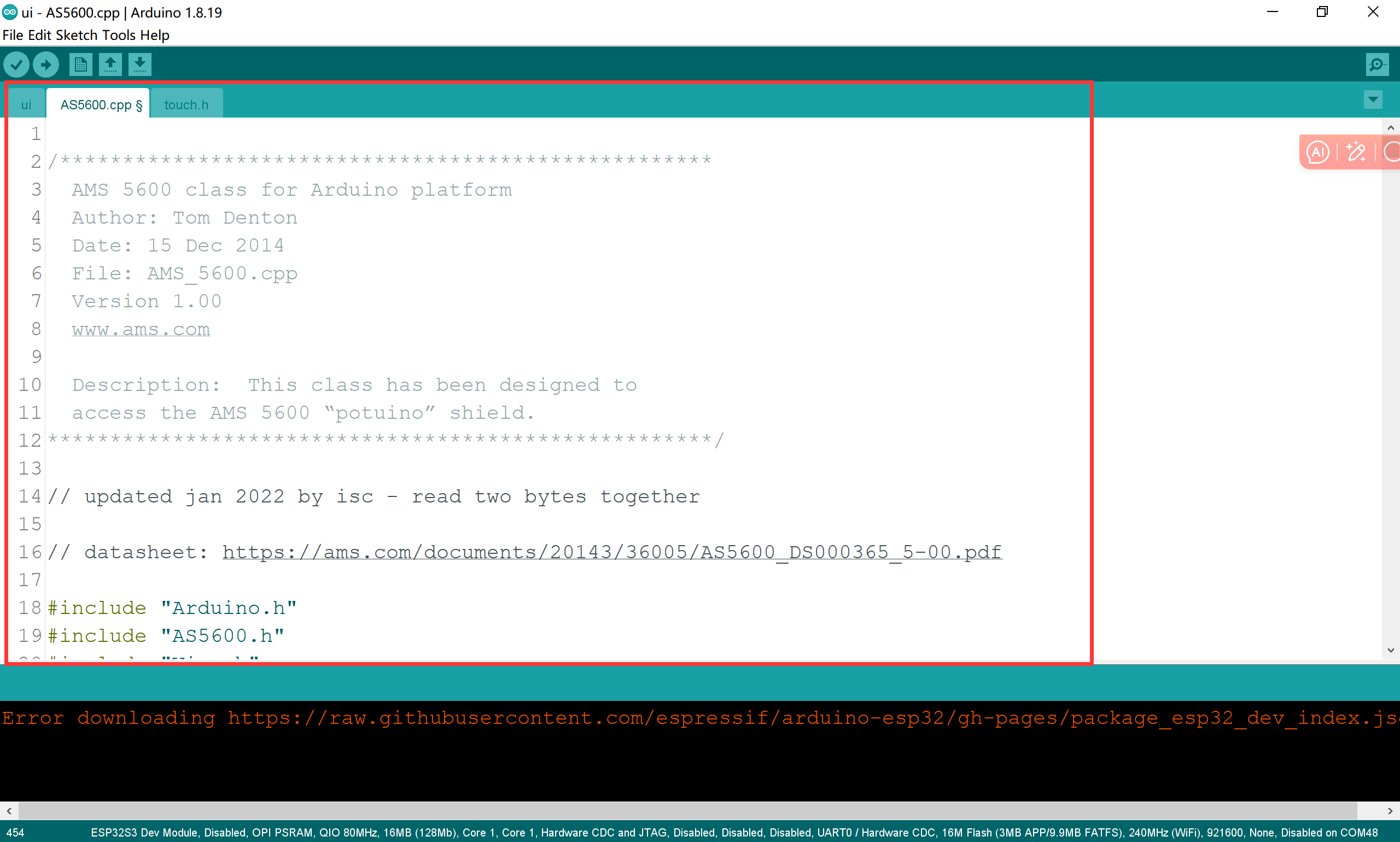
2.Add a driver library for the AS5600.
- Copy and paste AS5600.cpp, AS5600.h as a same way.


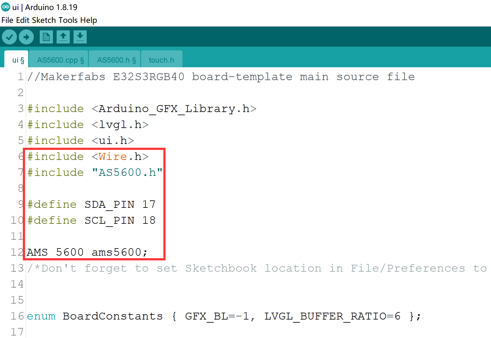
3.Add the library and define its pins, then enable the IIC pin.
#include <Wire.h>
#include "AS5600.h"

#define SDA_PIN 17
#define SCL_PIN 18

AMS_5600 ams5600;
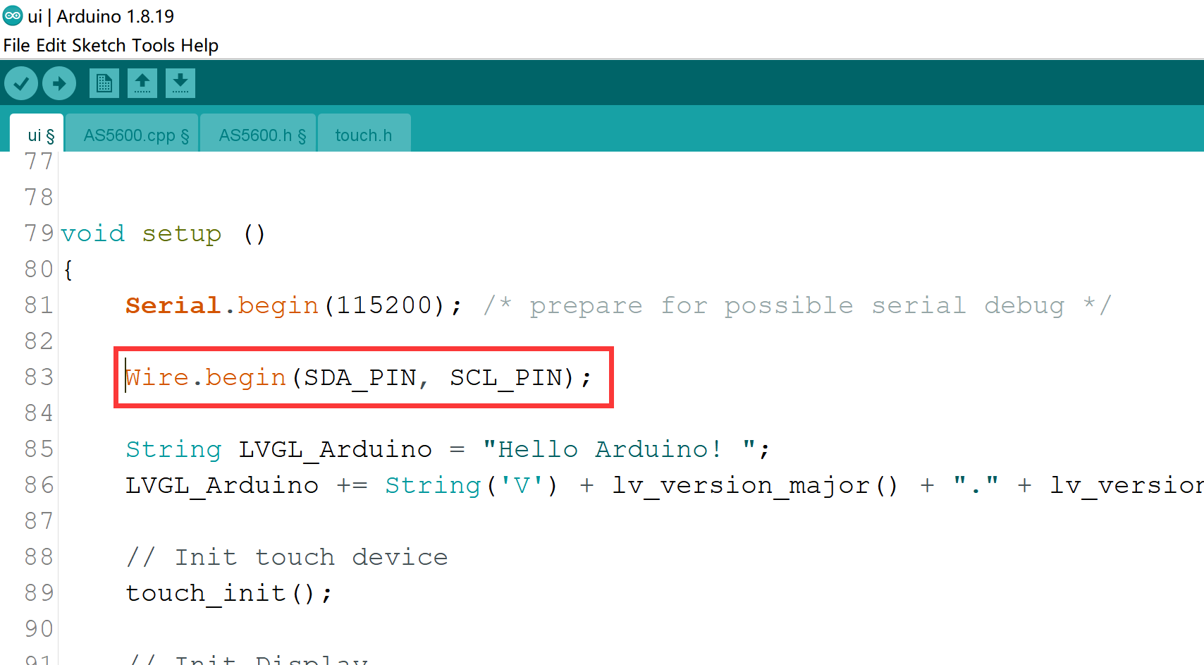
Wire.begin(SDA_PIN, SCL_PIN);
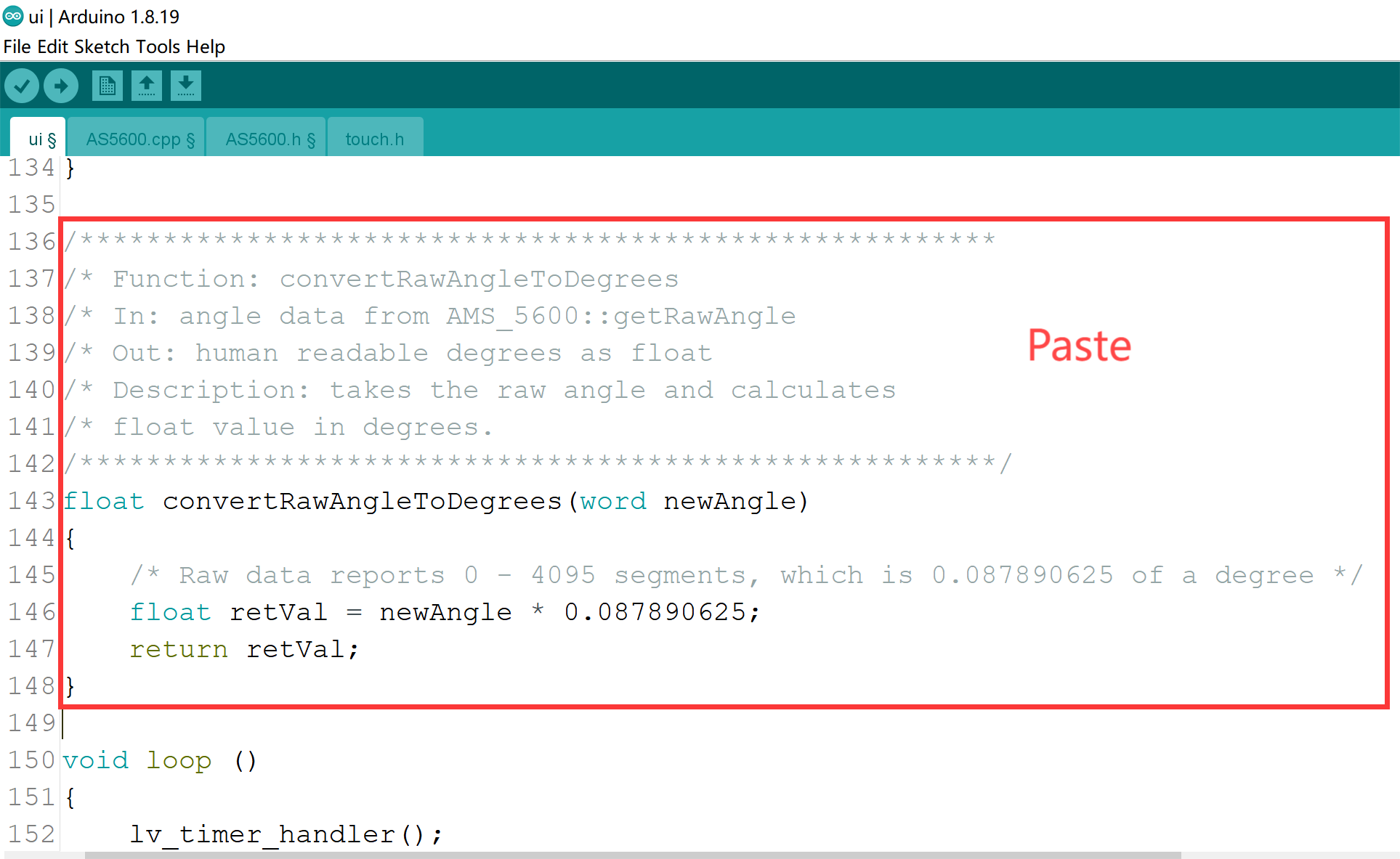
4.Add an Angle conversion function.
/*******************************************************
/* Function: convertRawAngleToDegrees
/* In: angle data from AMS_5600::getRawAngle
/* Out: human readable degrees as float
/* Description: takes the raw angle and calculates
/* float value in degrees.
/*******************************************************/
float convertRawAngleToDegrees(word newAngle)
{
    /* Raw data reports 0 - 4095 segments, which is 0.087890625 of a degree */
    float retVal = newAngle * 0.087890625;
    return retVal;
}
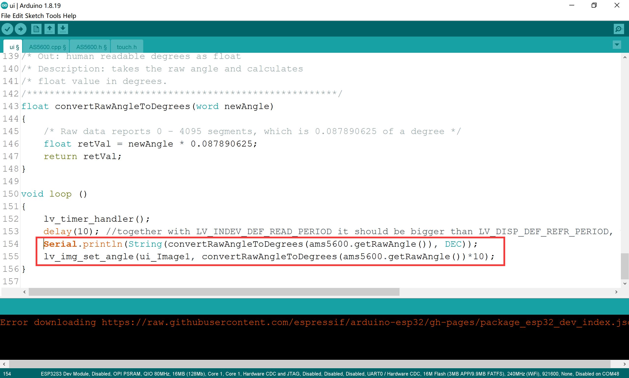
5.Serial Monitor to print Angle value and then the Angle of the knob is designed as the original Angle value, because the rotation Angle of the SquareLine image is 10 times the original Angle, so it needs to be multiplied by 10.
Serial.println(String(convertRawAngleToDegrees(ams5600.getRawAngle()), DEC));
lv_img_set_angle(ui_Image1, convertRawAngleToDegrees(ams5600.getRawAngle())*10);
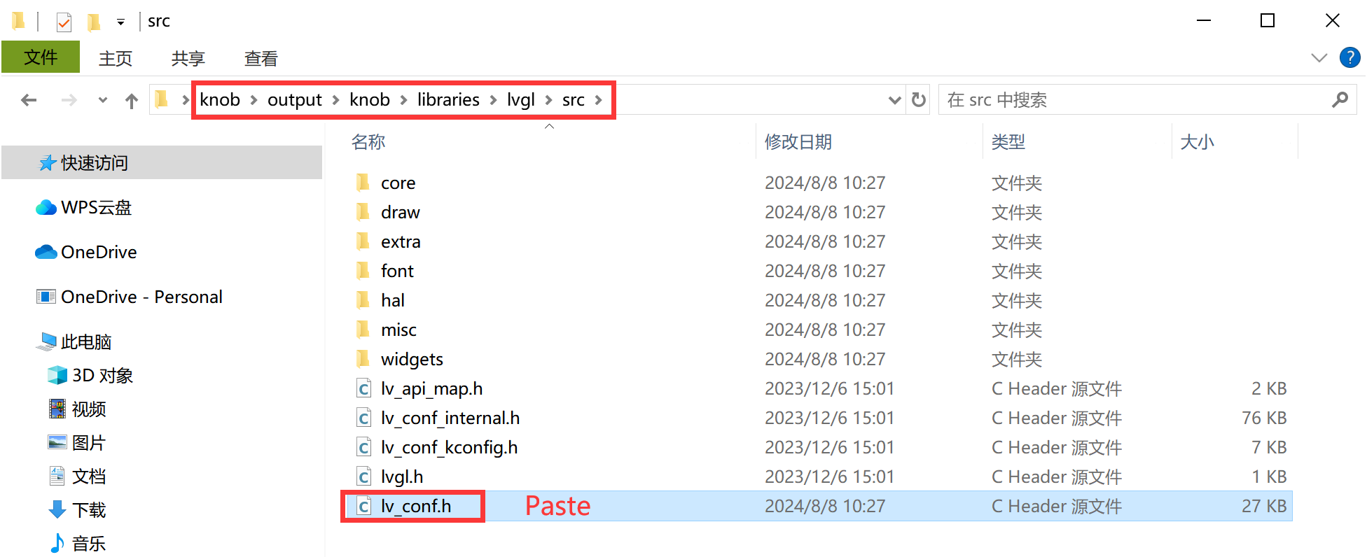
6.Click on the code project document you just output. Copy the lv_conf.h file into the “src” folder in the LVGL folder in libraries.

7.copy these four files into the Arduino library.


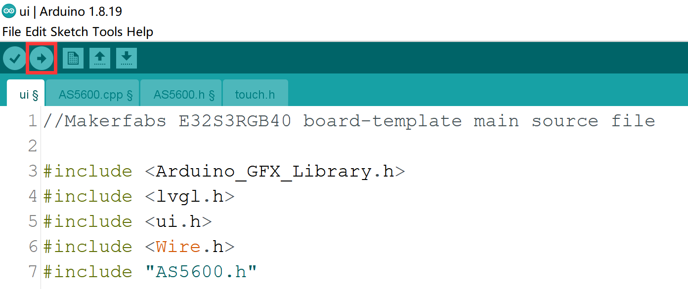
8.Go back to the Arduino, connect the screen with USB, select the com port and the board of the ESP32S3 and click upload.
Result
6. FAQ
You can list your question here or contact techsupport@makerfabs.com for technology support. Detailed descriptions of your question will be helped to solve your question.
-
Q1: Why the display fails to respond sometimes I touch?
-
A1: The touching interface is loose, please reconnect it.
Q2: I get the error "no matching function for call to 'Arduino_ESP32RGBPanel::Arduino_ESP32RGBPanel(int, int, int, int, int, int, int, int, int, int, int, int, int, int, int, int, int, int, int, int, int, int, int)'); ^" when I compile the code, how to solve it?

A2: Mabe you use the newest ArduinoGFX v1.4.7 not the tested v1.3.1. The oringinal code need to make some changes to support v1.4.7 as below:
#if 0  //for Arduino_GFX_Library v1.3.1
Arduino_ESP32RGBPanel *bus = new Arduino_ESP32RGBPanel(
    1 /* CS */, 12 /* SCK */, 11 /* SDA */,
    45 /* DE */, 4 /* VSYNC */, 5 /* HSYNC */, 21 /* PCLK */,
    39 /* R0 */, 40 /* R1 */, 41 /* R2 */, 42 /* R3 */, 2 /* R4 */,
    0 /* G0/P22 */, 9 /* G1/P23 */, 14 /* G2/P24 */, 47 /* G3/P25 */, 48 /* G4/P26 */, 3 /* G5 */,
    6 /* B0 */, 7 /* B1 */, 15 /* B2 */, 16 /* B3 */, 8 /* B4 */
);

Arduino_ST7701_RGBPanel *gfx = new Arduino_ST7701_RGBPanel(
    bus, GFX_NOT_DEFINED /* RST */, 0 /* rotation */,
    true /* IPS */, 480 /* width */, 480 /* height */,
    st7701_type1_init_operations, sizeof(st7701_type1_init_operations),
    true /* BGR */);
#endif  //end of  for Arduino_GFX_Library v1.3.1

#if 1 //for Arduino_GFX_Library v1.4.7
Arduino_DataBus *bus = new Arduino_SWSPI(
    GFX_NOT_DEFINED /* DC */, 1 /* CS */,
    12 /* SCK */, 11 /* MOSI */, 13 /* MISO */);

Arduino_ESP32RGBPanel *rgbpanel = new Arduino_ESP32RGBPanel(
    45 /* DE */, 4 /* VSYNC */, 5 /* HSYNC */, 21 /* PCLK */,
    39 /* R0 */, 40 /* R1 */, 41 /* R2 */, 42 /* R3 */, 2 /* R4 */,
    0 /* G0 */, 9 /* G1 */, 14 /* G2 */, 47 /* G3 */, 48 /* G4 */, 3 /* G5 */,
    6 /* B0 */, 7 /* B1 */, 15 /* B2 */, 16 /* B3 */, 8 /* B4 */,
    1 /* hsync_polarity */, 10 /* hsync_front_porch */, 8 /* hsync_pulse_width */, 50 /* hsync_back_porch */,
    1 /* vsync_polarity */, 10 /* vsync_front_porch */, 8 /* vsync_pulse_width */, 20 /* vsync_back_porch */);

Arduino_RGB_Display *gfx = new Arduino_RGB_Display(
    480 /* width */, 480 /* height */, rgbpanel, 0 /* rotation */, true /* auto_flush */,
    bus, GFX_NOT_DEFINED /* RST */, st7701_type1_init_operations, sizeof(st7701_type1_init_operations));
#endif   //End of for Arduino_GFX_Library v1.4.7