Maduino Zero Canbus with RS485
1. Introduction
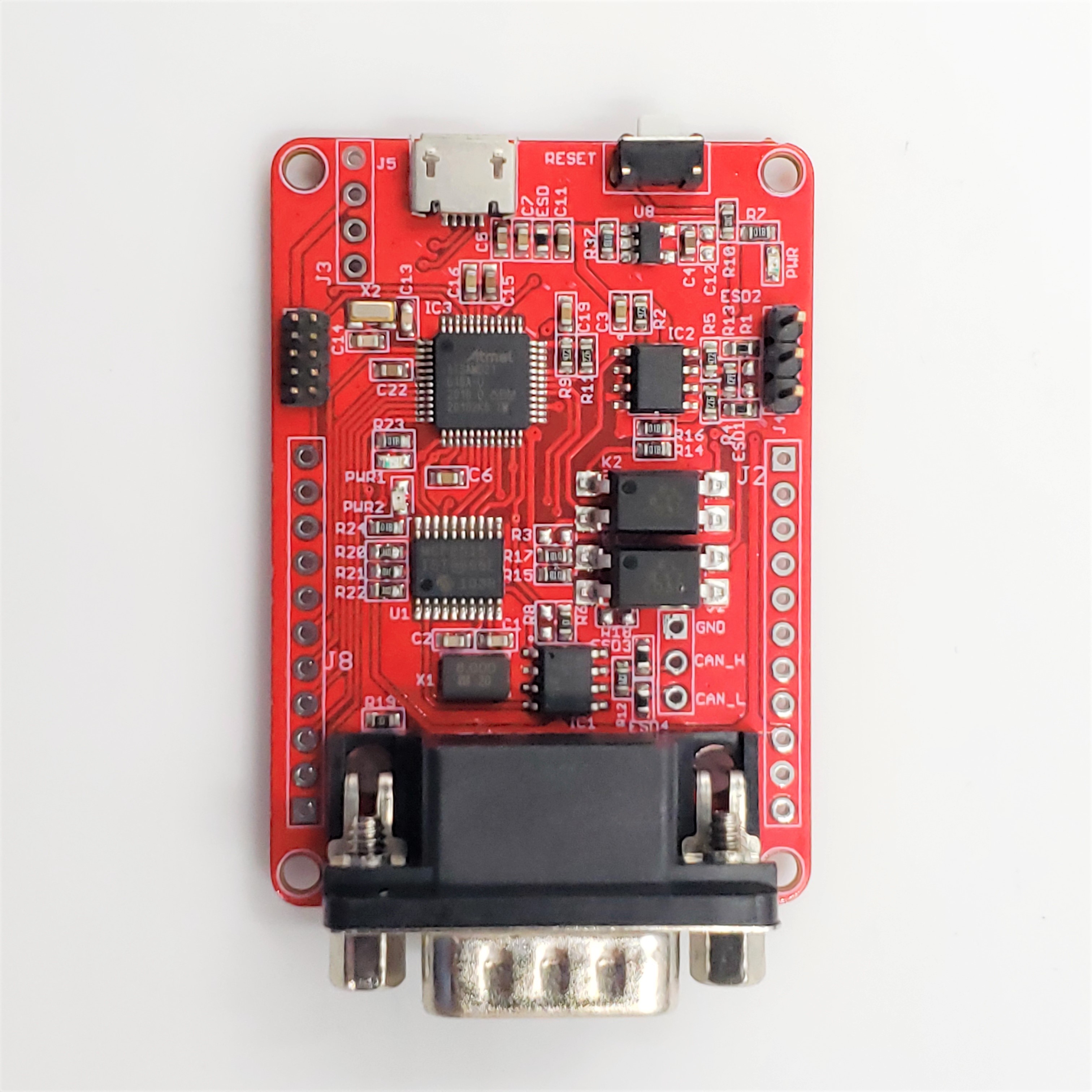
CAN-BUS is a common industrial communication bus because of its long travel distance, medium communication speed, and high reliability, it is the backbone of many protocols with applications in automation, industrial systems, building management. This Maduino Zero CAN-BUS based on SAMD21G18A, with the CAN controller MCP2515 and CAN transceiver MAX3051, to create a ready-to-use CAN-bus port. With this board, you can easily get/send your local data remotely with a standard CAN Bus. For example, you can collect local sensor data, using the Maduino zero ports, and send all the data to remote servers, to create remote-monitor with reliable CAN-Bus communication.
Model:MADCANB
2. Features
- ATMEL SAMD21G18A: 32-bit ARM® Cortex®-M0, Arduino Zero bootloader pre-loaded.
- CAN-BUS/ RS-485.
- Implements CAN V2.0 at 1M/s.
- MCP2515 CAN Bus controller and MAX3051 CAN Bus transceiver.
- Allows for Transmission Speeds Up to 16Mbps of RS-485.
- Industrial standard 9 pins sub-D connector.
3. Diagram
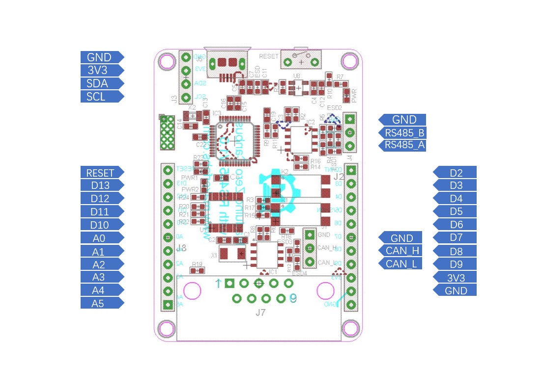
DB9 Interface:
| DB9 PIN | Description |
|---|---|
| 1 | GND |
| 3 | CAN_H |
| 5 | CAN_L |
4. Usage
4.1 Software setup
- After installed Arduino, there is no package to support the board (Arduino zero) that is needed to be installed.
- select tools ->Board -> Board Manager, search "Arduino zero" and install "Arduino SAMD Boards".
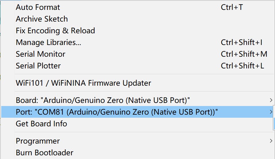
- Select Tools ->Board -> Arduino Zero (Native USB Port), select Tools -> Port -> com…
4.2 Test
Github: Maduino-Canbus-RS485
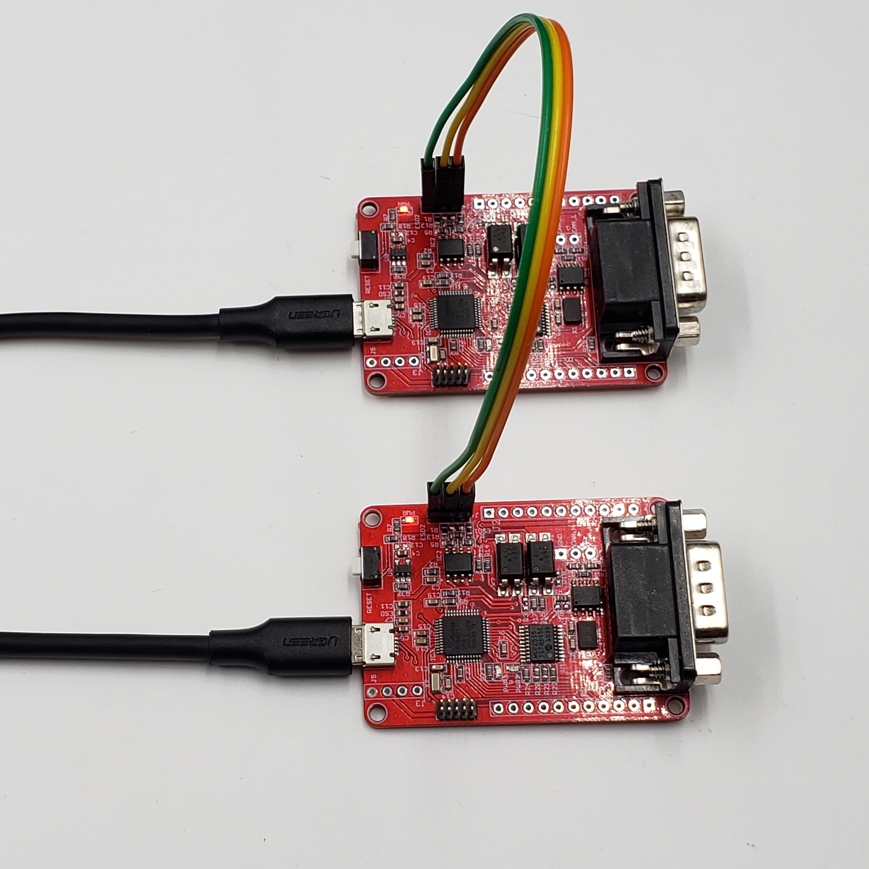
- The sensors or devices which can carry on RS485 or CANbus are connected to the board through cables. in this project, use the same board instead of the device being tested, and connected two boards by cables or Dupont lines to check the communication between boards.
- The pins connection is:
| Maduino Zero CANbus with RS485 | Devices or sensors |
|---|---|
| GND | GND |
| RS485_A | RS485_A |
| RS485_B | RS485_B |
| CAN_H | CAN_H |
| CAN_L | CAN_L |
4.3 CANBUS
- One board upload the code Maduino-CANbus-RS485/CAN_Sender/CAN_Sender.ino, and the other upload the code Maduino-CANbus-RS485/CAN_Receiver/CAN_Receiver.ino. Both programs include functions that can realize receiving and sending data in CANBUS communication mode.
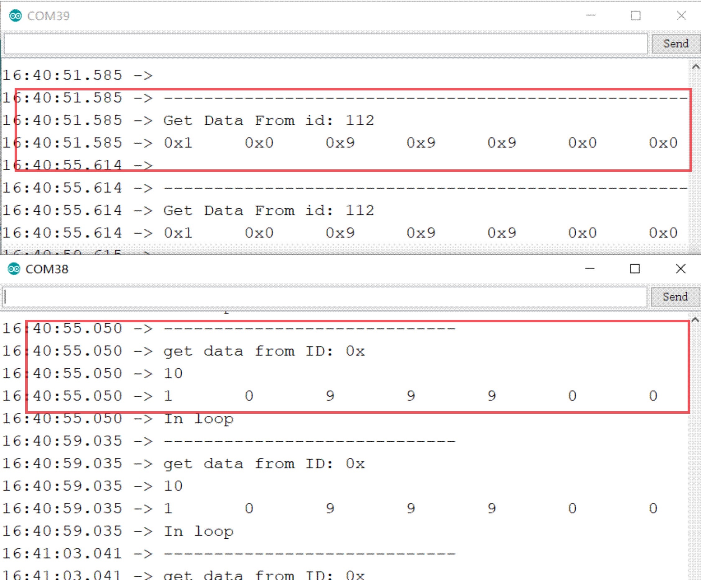
- After the upload is successful, open the Serial Monitor and you can observe that the board is receiving and sending data cyclically through CANBUS. The green indicator light on the board will flash when data is received.
5. RS485
- Upload the code Maduino-CANbus-RS485/RS485/RS485.ino to two boards.
- After the uploading is successful, open the Serial Monitor and send data, and it will receive the data through RS485 communication on another board. The blue indicator light on board will flash when data is received.
6. FAQ
You can list your question here or contact techsupport@makerfabs.com for technology support. Detailed descriptions of your question will be helped to solve your question.