MaTouch_ESP32S3-SPI-TFT-with-AI-2.8-ST7789V
1. Introduction
The MaTouch_ESP32S3-SPI-TFT-with-AI-2.8-ST7789V base on ESP32S3, featuring a 2.8-inch display with capacitive touch. It comes with a wide range of onboard peripherals, including dual-channel INMP441 microphone input, MAX98357 audio output, a MicroSD card slot, camera interface, WS2812 RGB LED, RTC (real-time clock), battery, and both USB-to-serial and native USB interfaces. With its rich feature set, this board is ideal for embedded applications such as voice recognition, graphical user interfaces.
2. Features
- Controller: ESP32-S3
- Wireless: WiFi& Bluetooth 5.0
- LCD: 2.8", 320x240 resolution
- LCD Driver: ST7789V
- LCD interface: SPI
- Flash: 16MB Flash
- PSRAM: 8MB
- Touch Panel: 5 Points Touch, Capacitive
- Touch Panel Driver: GT911
- USB: 1 * USB to UART, 1 * USB_native
- Power Supply: USB Type-C 5.0V(4.0V~5.25V)
- Button: Flash button and reset button
- Expansion interface: 4 * GPIO
- Camera: Yes
- MicroSD: Yes
- RGB LED: 1XWS2812
- RTC: Yes
- Charger: Yes
- Battery Connector: Yes
- Microphone input: 2CH INMP441
- Audio output: MAX98357(3.2W@4Ω)
- Arduino support: Yes
- LVGL support: Yes
3. Usage in Arduino IDE
- Install the Arduino IDE V1.8.19/V2.3.4 If you haven’t installed the ESP32 Board SDK yet, follow the steps in this guide to get started quickly.
For the ESP32-S3 Development board version, we recommend using versions that have been verified, such as 2.0.16, which is more stable, and less prone to errors.
Note: Different computers may have different port numbers when connecting to a development board. Please select the correct port number based on the development board you are connecting to.
Please download the relevant driver libraries before using these demos.
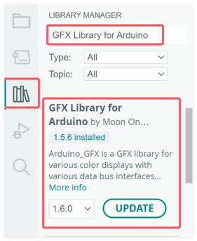
1.Install Arduino_GFX_Library V1.5.6
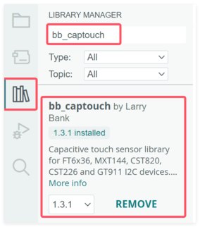
2.Install bb_captouch V1.3.1
3.1 Display_Touch_Camera
This demo demonstrates the combined use of display, touch, and camera functionalities.The screen first shows an image. Then, the interface automatically switches to a drawing board mode, allowing the user to freely draw using the touchscreen. A square button is located at the bottom right corner of the screen; clicking this button switches the application to camera mode.
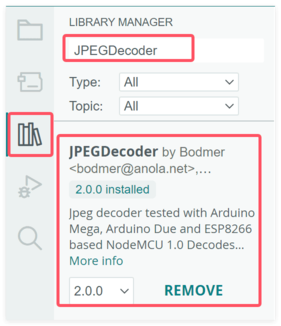
- Install JPEGDecoder V2.0.0
- Open the Display_Touch_Camera by Arduino.
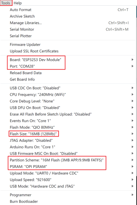
Use Type-C USB cable to connect the board and PC, and select the development board "ESP32S3 Dev Module" and the port.
-
Select "Tools > board:"xxx" > ESP32 Arduino > ESP32S3 Dev Module".
-
Select "Tools > Port", Select the port number of the board.
-
Select Flash Size is 16MB(128MB), Partition Scheme is 16M Flash (3MB APP/9.9MB FATFS), PSRAM is OPI PSRAM.
- Click the Upload button in the Arduino IDE and wait for the code to upload.
Results
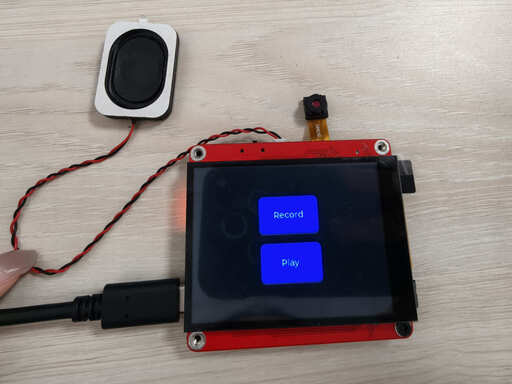
3.2 Record and Play Demo
The Record and Play demo implements a voice recorder functionality. It allows the user to record audio through a microphone, save the recording to an SD card, and later play back the recorded audio through a speaker.
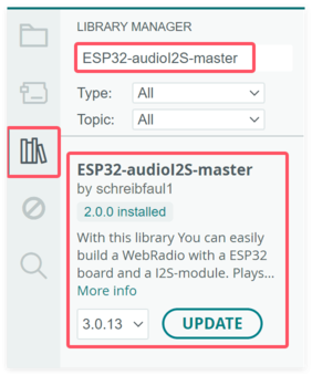
- Install ESP32-audioI2S-master V2.0.0
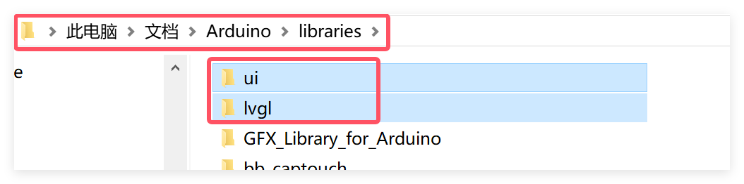
- Download and copy the ui and lvgl library into the arduino library.(Usually located at C:\Users\Username\Documents\Arduino\libraries)
- Open the Record_Play_Demo by Arduino.
Use Type-C USB cable to connect the board and PC, and select the development board "ESP32S3 Dev Module" and the port.
-
Select "Tools > board:"xxx" > ESP32 Arduino > ESP32S3 Dev Module".
-
Select "Tools > Port", Select the port number of the board.
-
Select Flash Size is 16MB(128MB), Partition Scheme is 16M Flash (3MB APP/9.9MB FATFS), PSRAM is OPI PSRAM.
-
Click the Upload button in the Arduino IDE and wait for the code to upload.
Results
3.3 RTC Demo
This demo uses a real-time clock module to keep track of the current time and displays the time continuously on the screen using the LVGL graphics library.
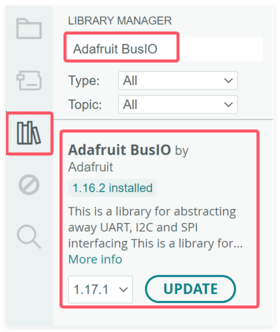
- Install RTClib V2.1.4

- Install Adafruit BusIO V1.16.2
- Download and copy the ui and lvgl library into the arduino library.(Usually located at C:\Users\Username\Documents\Arduino\libraries)
- Open the Clock_demo by Arduino.
Use Type-C USB cable to connect the board and PC, and select the development board "ESP32S3 Dev Module" and the port.
-
Select "Tools > board:"xxx" > ESP32 Arduino > ESP32S3 Dev Module".
-
Select "Tools > Port", Select the port number of the board.
-
Select Flash Size is 16MB(128MB), Partition Scheme is 16M Flash (3MB APP/9.9MB FATFS), PSRAM is OPI PSRAM.
-
Click the Upload button in the Arduino IDE and wait for the code to upload.
Results
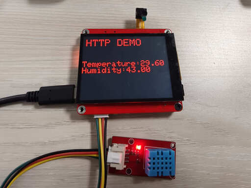
3.4 HTTP Demo
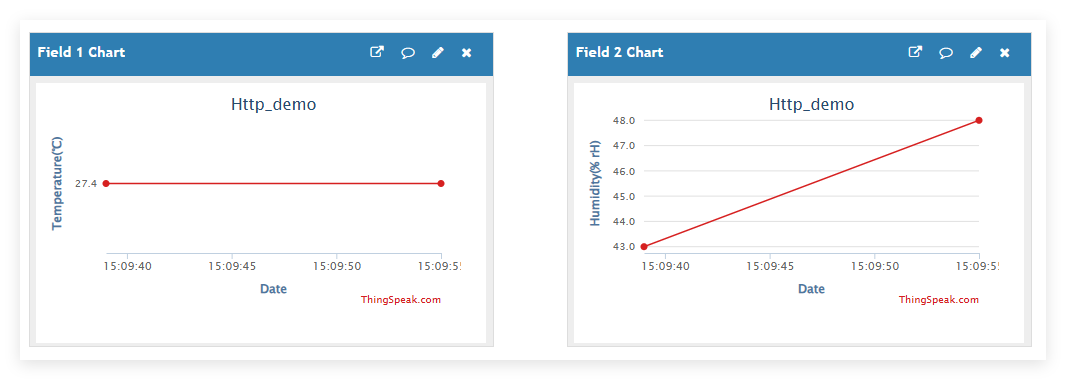
The HTTP demo uses DHT11 to collect temperature and humidity data and uploads the data to Thingspeak via the HTTP protocol.
Thingspeak
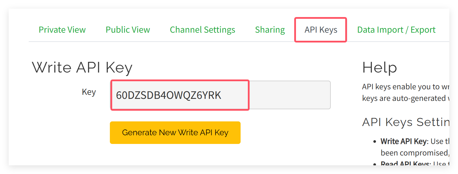
To transmit the data to your Thingspeak channel, it has to create a new channel and get the APIKEY information. Then replace the APIKEY in the code with yours.
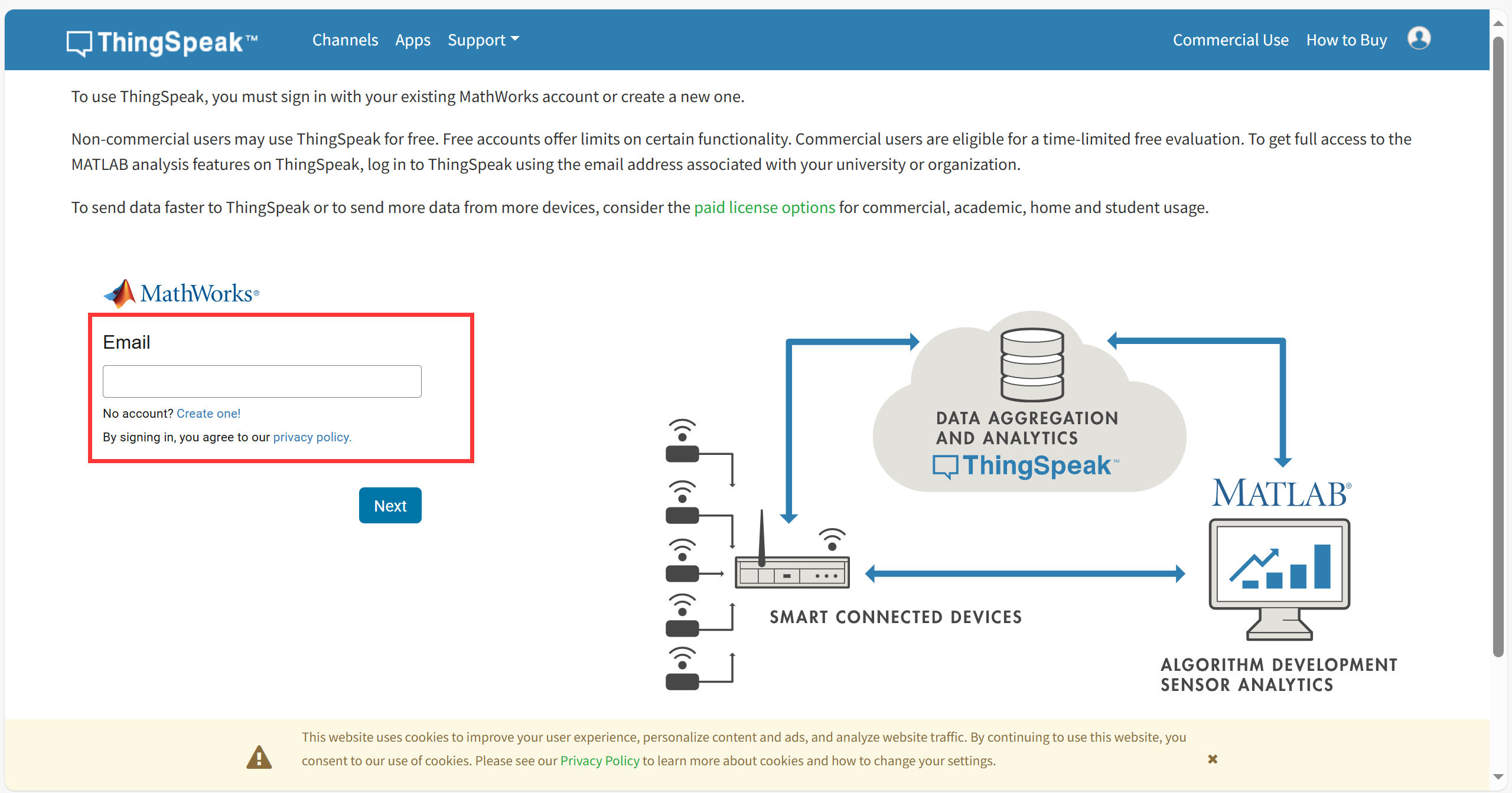
- sign in or sign up for ThingSpeak
If you already have an account, log in and enter the password, otherwise click Create one to register.
- Create new channel
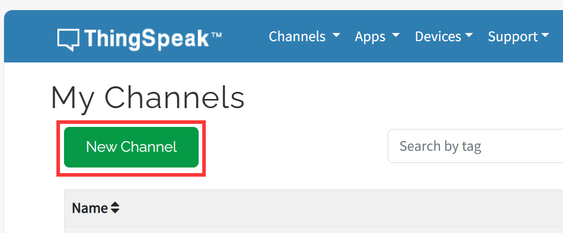
Select "Channel --> My Channels".
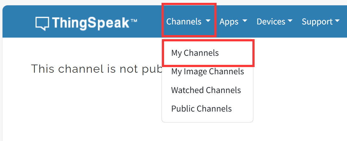
click "New Channel".
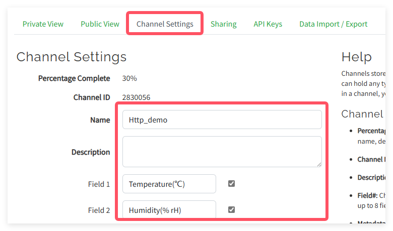
Write the name and field information and click Save Channel to create successfully.
Arduino
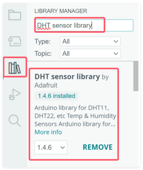
- Install DHT sensor library v1.4.6
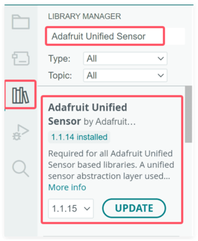
- Install Adafruit Unified Sensor V1.1.14
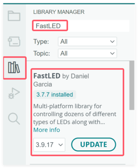
- Install FastLED V3.7.7
-
Open the HTTP_demo by Arduino.
-
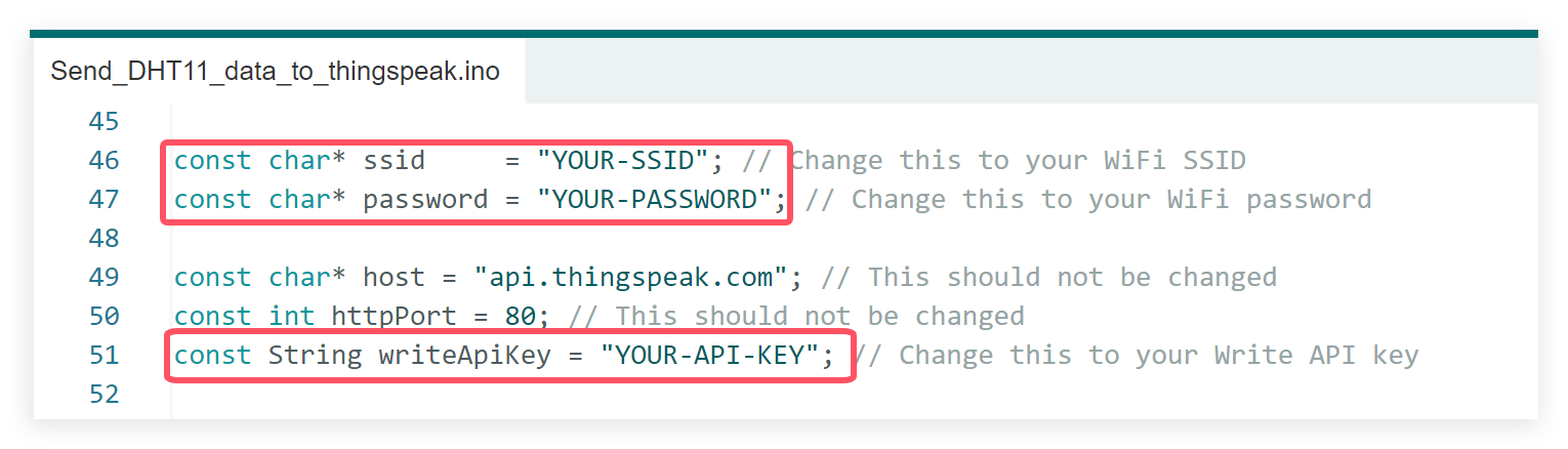
In order to view the data in your own channel, you need to modify the APIKEY in the code.
- Modify the APIKEY, your WiFi name and password in the code.
Use Type-C USB cable to connect the board and PC, and select the development board "ESP32S3 Dev Module" and the port.
- Click the Upload button in the Arduino IDE and wait for the code to upload.
Results
3.5 MQTT Demo
This demo implements button synchronization between two screens. When the button on one board is pressed, the button state on the other board is automatically updated as well.
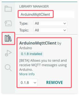
- Install ArduinoMqttClient V0.1.8
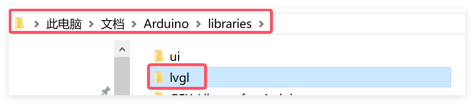
- Download and copy the lvgl library into the arduino library.(Usually located at C:\Users\Username\Documents\Arduino\libraries)
-
Open the MQTT_demo by Arduino.
-
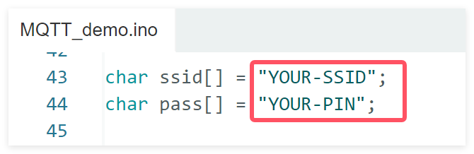
Modify your WiFi name and password in the code.
Use Type-C USB cable to connect the board and PC, and select the development board "ESP32S3 Dev Module" and the port.
-
Select "Tools > board:"xxx" > ESP32 Arduino > ESP32S3 Dev Module".
-
Select "Tools > Port", Select the port number of the board.
-
Select Flash Size is 16MB(128MB), Partition Scheme is 16M Flash (3MB APP/9.9MB FATFS), PSRAM is OPI PSRAM.
-
Click the Upload button in the Arduino IDE and wait for the code to upload.
-
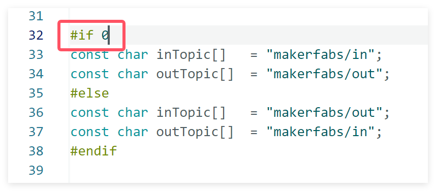
Prepare the other board, change the code to 0, and upload it following the same steps.
Results

3.6 Connect to ChatGPT
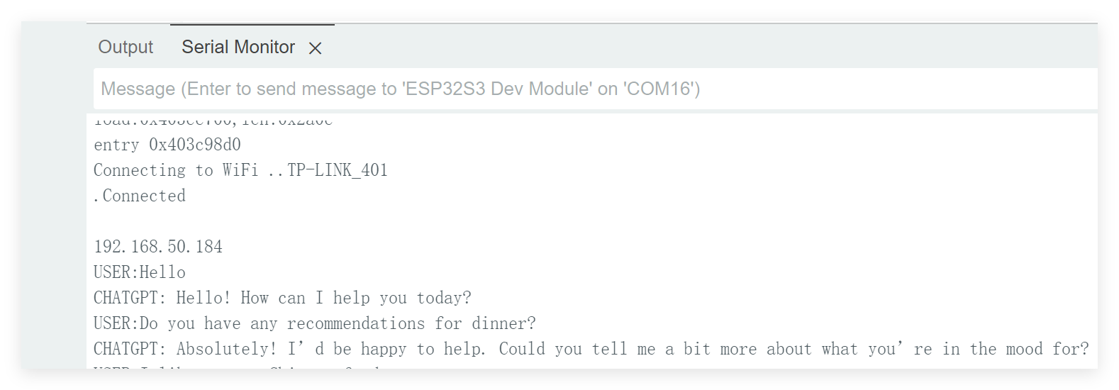
This demo shows how to integrate ChatGPT into your board, enabling a Q&A interaction through the serial interface.
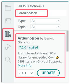
- Install ArduinoJson V7.2.0
-
Open the ChatgptwithMatouch by Arduino.
-
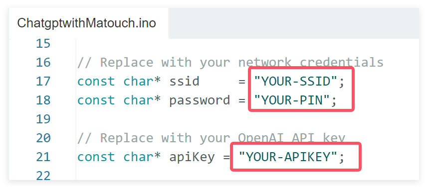
Modify your WiFi name, password and APIKEY in the code.
Use Type-C USB cable to connect the board and PC, and select the development board "ESP32S3 Dev Module" and the port.
- Click the Upload button in the Arduino IDE and wait for the code to upload.
Results
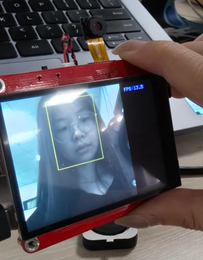
3.7 Face Detect
This demo detects human faces in real time using the camera. When a face is detected, a rectangle is drawn around it on the display to highlight the detected area.
- Open the Face_Detect by Arduino.
Use Type-C USB cable to connect the board and PC, and select the development board "ESP32S3 Dev Module" and the port.
-
Select "Tools > board:"xxx" > ESP32 Arduino > ESP32S3 Dev Module".
-
Select "Tools > Port", Select the port number of the board.
-
Select Flash Size is 16MB(128MB), Partition Scheme is 16M Flash (3MB APP/9.9MB FATFS), PSRAM is OPI PSRAM.
-
Click the Upload button in the Arduino IDE and wait for the code to upload.
Results
3.8 Speech_to_Text
3.9 Text_to_Speech
3.10 AI_XiaoZhi
4. FAQ
You can list your questions here or contact techsupport@makerfabs.com for technology support. Detailed descriptions of your question will help to solve your question.