GPRS GSM GPS Shield (SIMCOM- SIM808)
Introduction
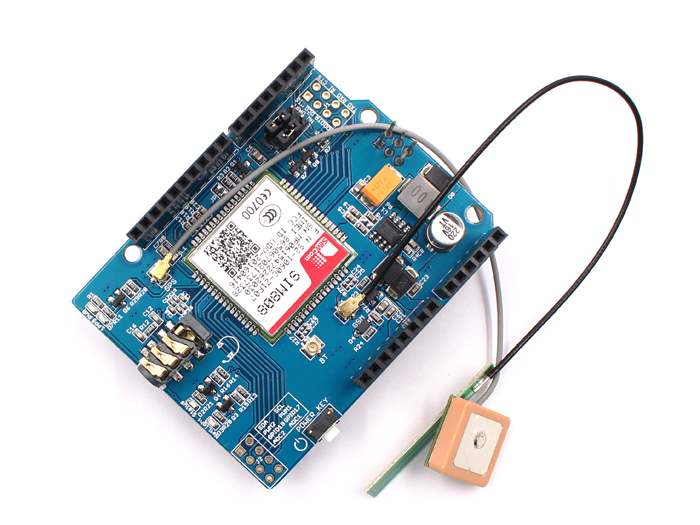
This GPRS GSM GPS Shield is based on the SIM808 GSM GPRS GPS all-in-one cellular phone module. You can add location-tracking, voice, text, SMS and data to your project. This shield fits right over your Arduino or Maduino, it is easy to use. This shield fits right over your Arduino or compatible. At the heart is a powerful GSM cellular module (we use the latest SIM808) with integrated GPS. The module is controlled by AT command via UART and supports 3.3V and 5V logical levels.
Model:OAS808SIM
Features
- Quad-band 850/900/1800/1900MHz - connect onto any global GSM network with any 2G SIM (in the USA, T-Mobile is suggested)
- Fully-integrated GPS
- Make and receive voice calls using a headset or an external 32Ω speaker + electret microphone
- Send and receive SMS message
- AT command interface with "auto baud" detection
- Send and receive GPRS data (TCP/IP, HTTP, etc.)
- GPS L1 C/A code
- 22 tracking /66 acquisition channels
- Tracking: -165 dBm
- Cold starts: -148 dBm
- Time-To-First-Fix: Cold starts-32s (typ.),Hot starts-1s (typ.),Warm starts-5s (typ.)
- Accuracy: approx 2.5 meters
Interface Function
Connectors:
- Headset jack-This is a 'standard' TRRS 3.5mm phone headset jack with stereo earphone and mono microphone. Any 'iPhone' or 'Android' compatible (but not iPhone original) should work.
- uFL GSM connector-This is the GSM Antenna connector, an antenna is required to use the SIM808 shield!
- uFL GPS connector-This is the GPS Antenna connector, an antenna is required if you want to get GPS readings!
- uFL BT connector- This is the Bluetooth Antenna connector, in this version, there no have the Bluetooth function.
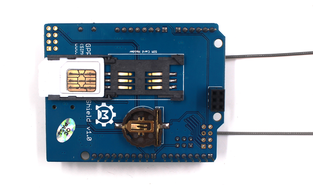
- SIM Connector: A 2G Mini SIM card is required to use the module. You can buy it in any cell phone shop. It must be a 2G GSM card.
-
VRTC Battery holder: Power supply for RTC. LEDs
-
PWR –Power light
- 1PPS –This is the 'pulse per second' output of the GPS
- Status – Power on status. Lit when the Cell module is booted and running
- NetLight – Network status. You can use this for checking the current state without sending an AT command
- 64ms on, 800ms off - the module is running but hasn't made connection to the cellular network yet
- 64ms on, 3 seconds off - the module has made contact with the cellular network and can send/receive voice and SMS
- 64ms on, 300ms off - the GPRS data connection you requested is active
By watching the blinks you can get a visual feedback on whats going on. POWER_KEY
- Power on or power off the SIM808.
Pins usage on Arduino
- D0 - Used if you select hardware serial port to communicate with SIM808
- D1 - Used if you select hardware serial port to communicate with SIM808
- D7 - Used if you select software serial port to communicate with SIM808
- D8 - Used if you select software serial port to communicate with SIM808
- D9 - Used for software control of the Power ON or Power OFF of the SIM808
Usage
SIM Card:
Insert a mini SIM card.
On its own, this shield can't do anything. It requires a microcontroller like an Arduino to drive it! You will also need some required accessories to make SIM808 shield work.
SIM Card! A 2G Mini SIM card is required to do anything on the cellular network. US AT&T no longer sells 2G SIMs and will shut off their 2G network, so for American customers we recommend any T-Mobile or reseller (TING, SIMPLE mobile, etc) that uses the T-Mobile network.
Assembly
Attaching Antennas: GSM antenna is required to use the Cellular module. If you want to use GPS as well, a passive GPS antenna is also required.
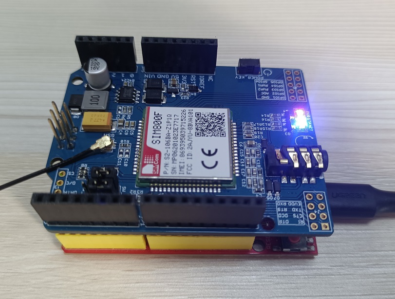
Note: Press and hold the power button for more than two seconds until the blue LED lights up, indicating that the module starts to work.
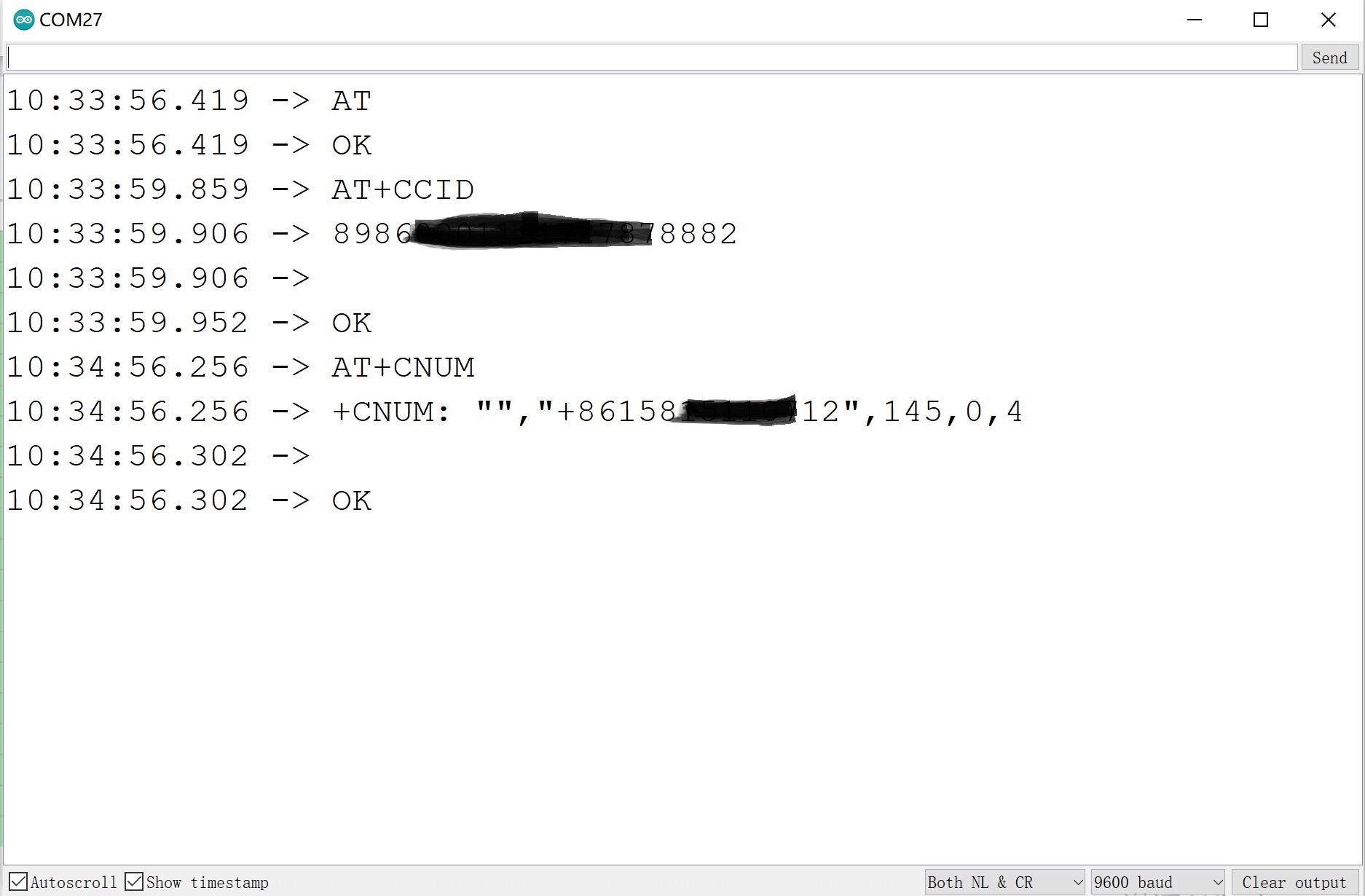
AT Command Test Demo
AT command test You can debug the AT command through the serial port to verify the function of the AT command
Download the AT_test Demo and verify and upload the code.
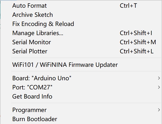
Select Arduino board: Arduino Uno , and Port:
By useing the AT command ,you can cheak the module whether runing well.
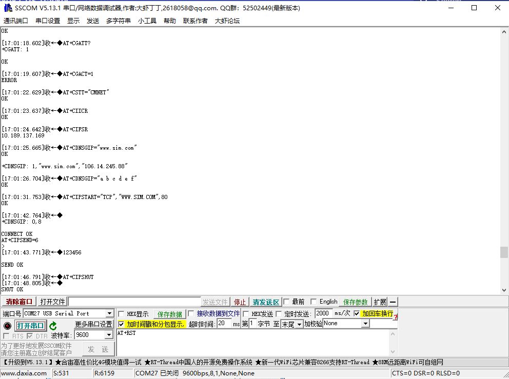
TCP Test Demo
Print the TCP_Test data with the serial port
The GPRS GSM GPS Shield can be capable of the GPRS connectivity for the Internet, to upload/download data with internet. The following simple example shows the starters how to access a website on the internet (Users need check the AT commands for how to access a website):
     sendData("AT+CCID",3000,DEBUG);
     sendData("AT+CREG?",3000,DEBUG);
     sendData("AT+CGATT?",1000,DEBUG);
     sendData("AT+CGACT=1",1000,DEBUG);
     sendData("AT+CSTT=\"CMNET\"",3000,DEBUG);
     sendData("AT+CIICR",1000,DEBUG);
     sendData("AT+CIFSR",1000,DEBUG);
     sendData("AT+CDNSGIP=\"www.sim.com\"",1000,DEBUG);
     sendData("AT+CDNSGIP=\"a b c d e f\"",1000,DEBUG);
     sendData("AT+CIPSTART=\"TCP\",\"WWW.SIM.COM\",80",5000,DEBUG);
     delay(10000);
     sendData("AT+CIPSEND=6",1000,DEBUG);
     sendData("123456",1000,DEBUG);
     delay(2000);
     sendData("AT+CIPSHUT",1000,DEBUG);
     sendData("AT+CIPCLOSE",1000,DEBUG);
     sendData("AT+CFUN=1,1",1000,DEBUG);
Open up the File: and upload to your Arduino wired up to the module.
Select Arduino board: Arduino Uno , and Port:
Verify and upload the code.
Once uploaded to your Arduino, open up the serial console at 9600 baud speed to show the test result:
FAQ
You can list your question here or contact techsupport@makerfabs.com for technology support. Detailed descriptions of your question will be helped to solve your question.