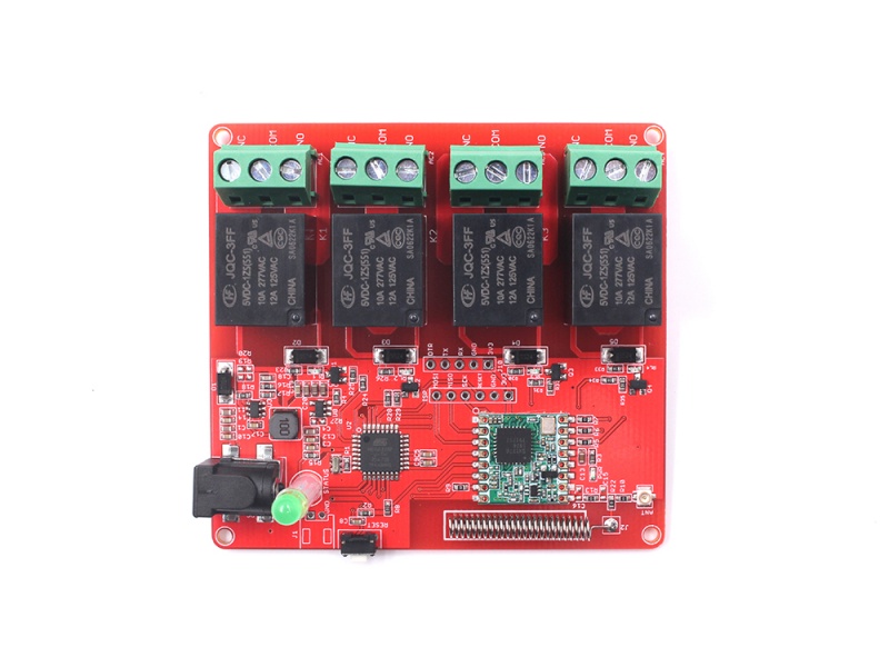
4-Channel Lora Relay-10A
Introduce
This Lora relay helps to extend the Lora networks to control actuators/ lights/ motors, to create automatic applications such as farming, aquaculture, and pasture. There 4 channels of the relay on the board, with max current 10A@277V AC. The main controller Atmega328P is Arduino Uno bootloader pre-loaded, which allows the users to program it with Arduino IDE directly.
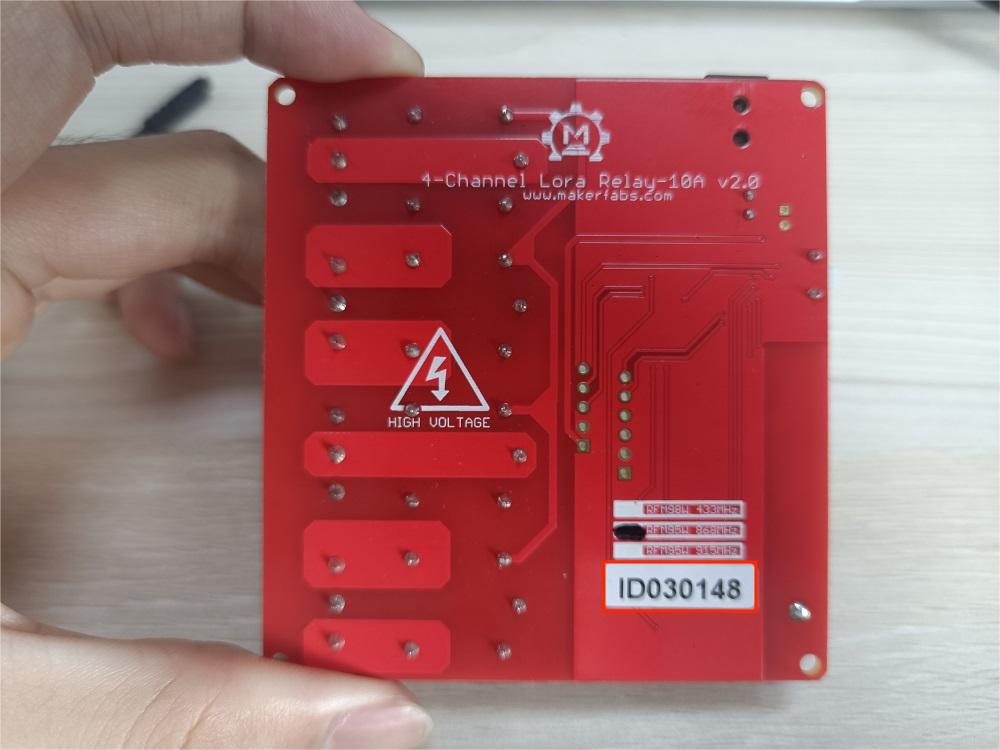
Modul: LORA4REL
4-Channel Lora Relay 10A offers bandwidth options ranging from 7.8125kHz to 500 kHz with spreading factors ranging from 6 to 12, there are three choices of working frequency.
| Item | Lora Module | working frequency |
|---|---|---|
| 4-Channel Lora Relay 10A 433M | RFM98W-433MHz/SX1278 | 433MHz |
| 4-Channel Lora Relay 10A 868M | RFM95W-868MHz | 868MHz |
| 4-Channel Lora Relay 10A 915M | RFM95W-915MHz | 915MHz |
Feature
- ATMEL Atmega328P: High Performance, Low Power Atmel®AVR® Classic Microcontroller
- Speed Grade: 20Mhz
- Flash: 32KBytes
- RAM: 2KBytes
- EEPROM: 1Kbytes
- Relay Type: General Purpose
- Rated Current of Relay Contact: 10A
- Coil Type of Relay: Non Latching
- Coil Voltage of Relay: 5V
- Switching Voltage of Relay: (277VAC, 28VDC) Max
- Lora Distance: >2 km
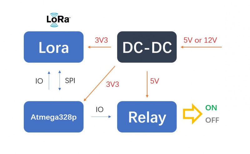
- DC 5V or DC 12V
Diagram
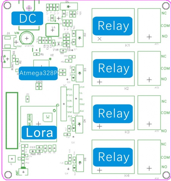
- Pins connection:
| Atmega328P | Relay |
|---|---|
| D4 | K1 |
| D3 | K2 |
| A3 | K3 |
| A2 | K4 |
- The following table lists all of the relay's pins and their functionality.
| Pin | Description |
|---|---|
| NC | Normally Closed |
| NO | Normally Opened |
| COM | Switch Common |
Normally, when the Atmega328P Pin output LOW the relay is not triggered, COM connects to NC. Contrarily, when the Atmega328P Pin output HIGH the relay is triggered, COM connects to NO.
Usage
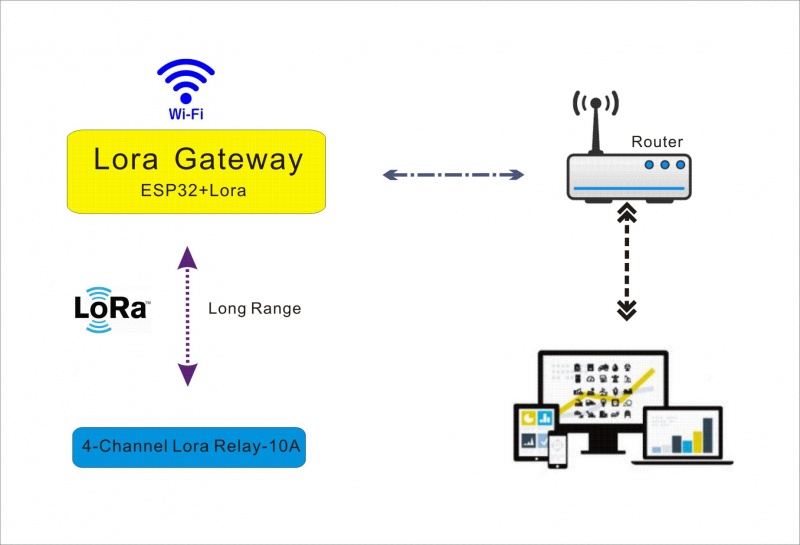
The 4-channel relay can be directly controlled by the device code, and the transmitter can be paired with the 4-channel relay through the device code to perform Lora communication. Also can establish a server through Lora gateway, realize web control relay function
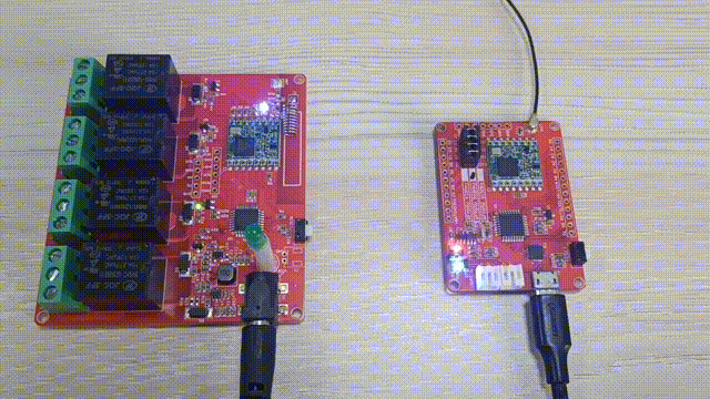
The user needs a Lora transmitter to transmit the corresponding signal to control the switch of the relay. We use the Maduino Lora radio to be a transmitter as an example.
Software setup
- Install RadioLib library. Click “Tools> Manager Libraries” to search for and install the RadioLib library.
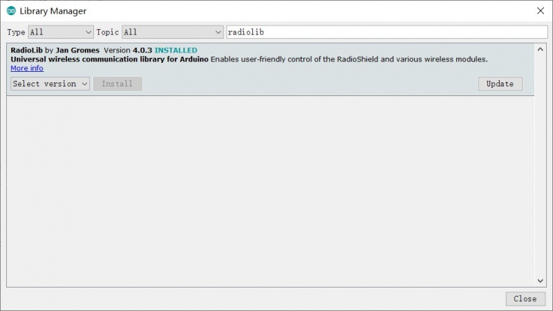
Note: It is recommended to use version 4.0.3, using the latest version may cause compilation failure.
- You can get the code from Github: Code
String node_id = String("IDXDEBUG");//modify the device code here.
- verify and upload code
Result:
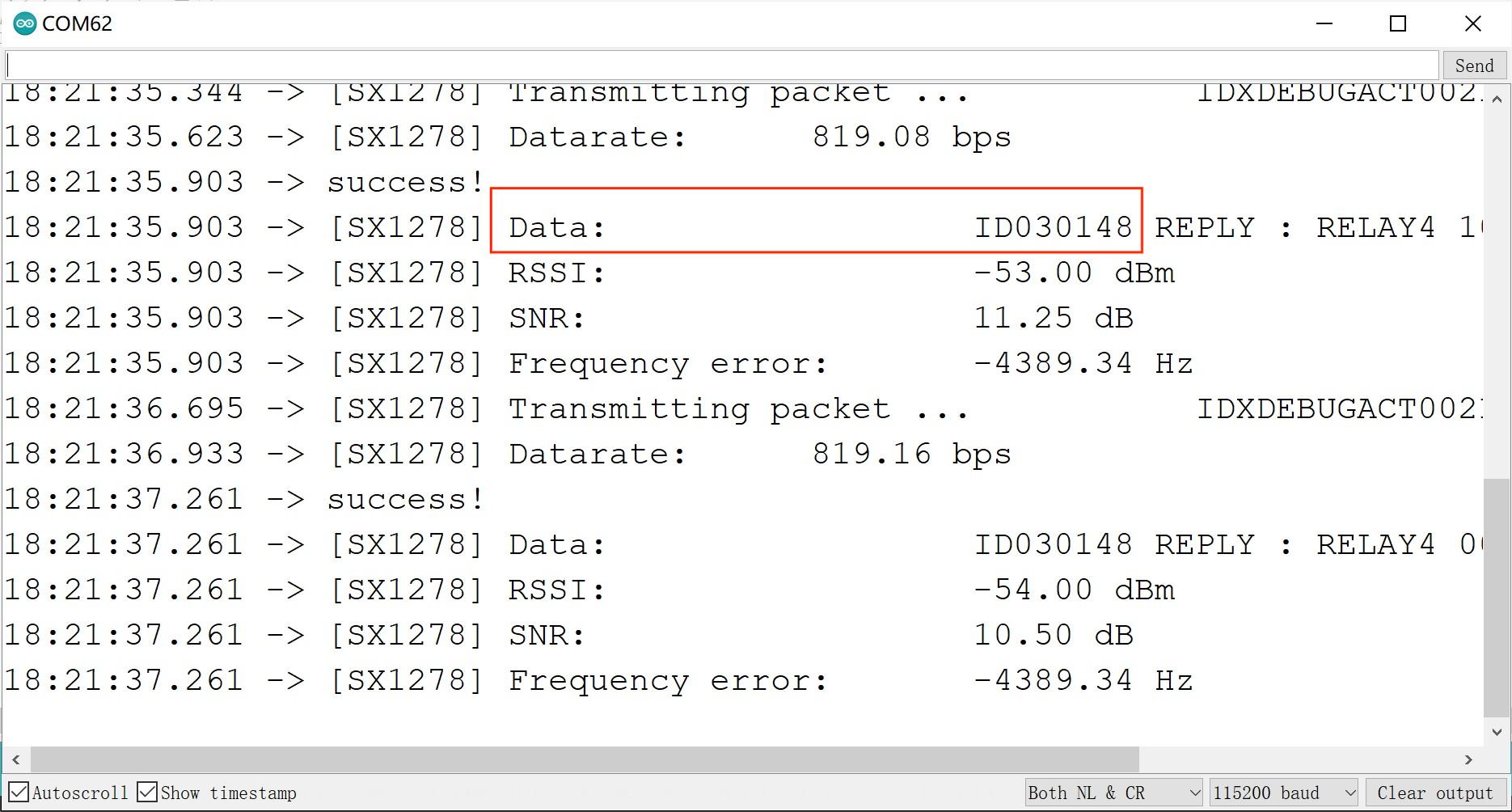
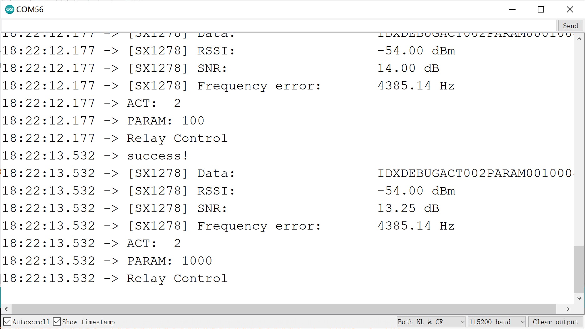
Open the serial port, and then we can see that the Maduino Lora Radio is continuously sending the signal to control the relay, and the other serial port monitor displays its own device code and the received control signal.
Lora gateway Control
- You can get the code from Github: Code
-
Install RadioLib library. Click “Tools> Manager Libraries” to search for and install the RadioLib library.
-
Upload the file Lora-Relay-4Channel/Example/Lora gateway cantrol--arduino/LoraRelay-receive/LoraRelay-receive.ino. The 4-Channel Lora Relay-10A module can be connected to the gateway and controlled by it.
Lora gateway
For detailed information about the gateway, please check [the Wiki of the Makepython Lora module](). Prepare the Makepython ESP32 module and the Makepython Lora module. Modify the wifi information in the code Lora-Relay-4Channel/Example/Lora gateway control--arduino/ESP32_lora/ESP32_lora.ino.
 const char *ssid = "Makerfabs";
 const char *password = "20160704";
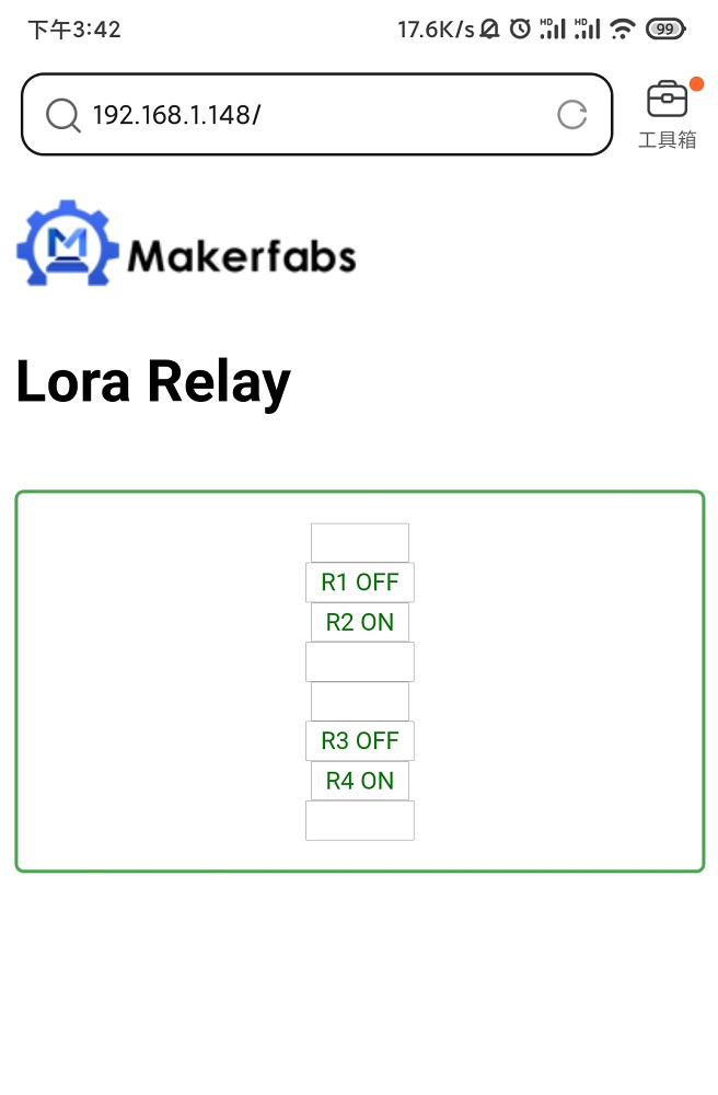
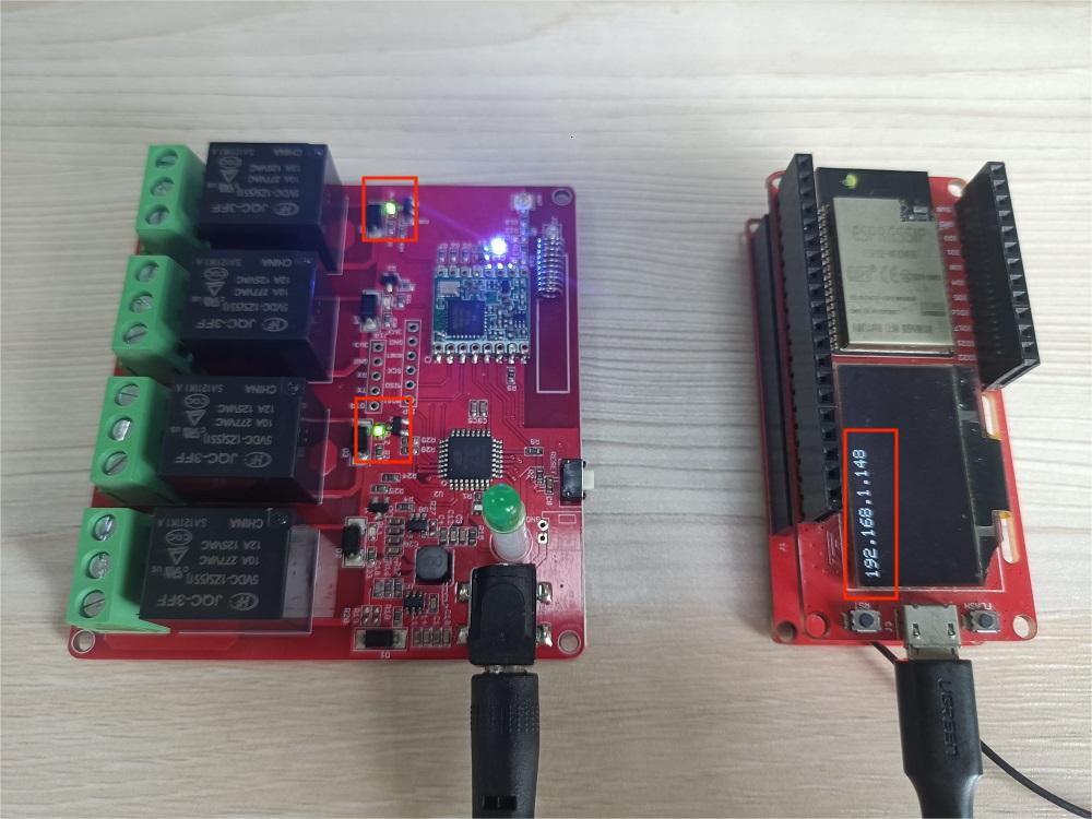
Upload the code Lora-Relay-4Channel/Example/Lora gateway control--Arduino/ESP32_lora/ESP32_lora.ino for the Makepython ESP32 module. Assemble the MaESP ESP32 module and the Makepython Lora, and power on. Open the address displayed on the screen of the MaESP ESP32 module on the browser. Before opening the browser, please make sure your electronic device is connected to the same WiFi. You can see the control interface of the relay.
Device 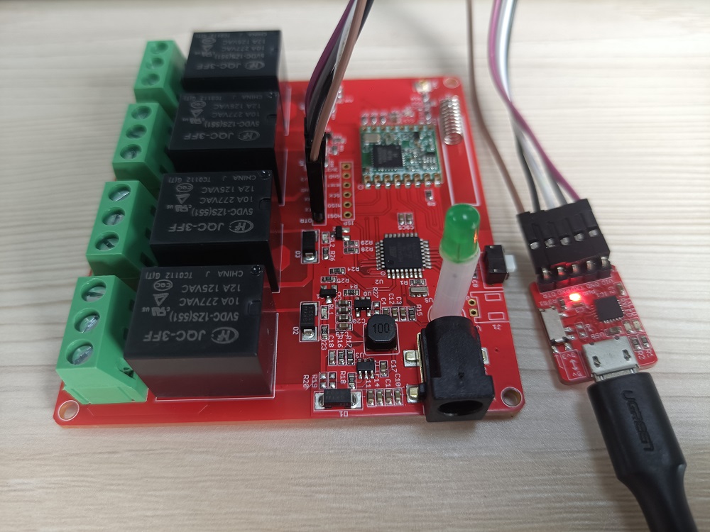 program burning。
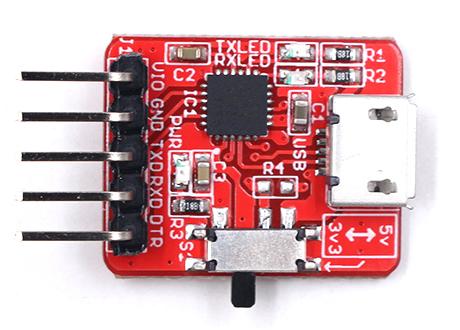
The USB TO UART TOOL is needed to connect the module and PC. The pins connections are:
| 4-Channel Lora Relay-10A | 4-Channel Lora Relay-10A |
|---|---|
| 3V3 | 3V3 |
| GND | GND |
| RX | TXD |
| TX | RXD |
| DTR | DTR |
The 4 channel relay program can refer to GitHub
#define FREQUENCY 434.0 // modify the communication frequency, it depends on your board.
F&Q
You can list your question here or contact techsupport@makerfabs.com for technology support. Detailed descriptions of your question will be helped to solve your question.