Maduino Zero A9G
1. Introduction
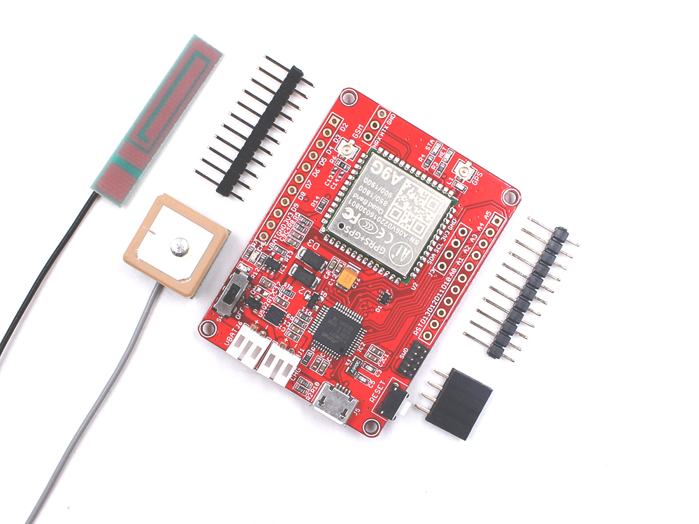
Maduino Zero A9G is an IoT (Internet of things) Solution based on the 32-bit Atmel’s SAMD21 MCU and GPRS/GSM+GPS module A9G. It integrates a micro Controller ATSAMD21G18, GRRS/GSM+GPS module A9G, which is the upgrade version of Maduino GPRS A7, power management, and storage, to make the A9G ready for real projects, for IoT projects such as smart-home, outdoor monitoring, etc. The Maduino Zero A9G GPS Tracker is based on the Arduino, users can program it with Arduino IDE, which is very easy and especially suit for non-programmers. There are also guide for users to learn how to create the first IoT project with this board, with which the starters can learn the hardware and programming skill quickly. With this board, you will easy to add text, SMS, and data to your project. It is good for your smart home project or GPS tracker and so on.
Model: OAC010A9G
Note: A9G is a GPRS/GSM+GPS module, while A9 is just a GPRS/GSM module not include GPS.
2. Features
- BAT Input Voltage: 3.4-4.2V
- ATSAMD21G18, 32-Bit ARM Cortex M0+
- Micro SIM connector
- Integrated Power Control System
- Support AT Command
- Quad-band: 850/900/1800/1900Mz
- Support GPS
- Support GPRS data traffic, the maximum data rate, download 85.6Kbps, upload 42.8Kbps
- Support SMS text messaging
- Support USB power charge
- Support Micro SD Card
- Interface: I2C/SPI/UART/18*GPIO
- Arduino compatible
- Working Temperature: -40 – 85℃
- Default baud rate: 115200
- Size: 40*55mm
3. Interface Function
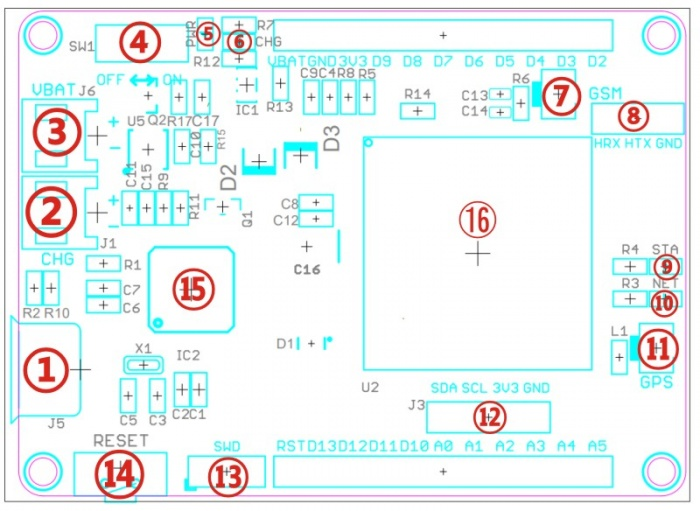
① Micro USB: 5V power input, USB to serial communication
② CHG: 5V power input, can connect the solar panel to charge the lipo battery
③ VBAT: 3.7V Lipo battery connector
④ SW1:Switch on/off
⑤ PWR: Power indicate
⑥ CHG: Charge indicate
⑦ GSM: GSM Antenna IPX Interface
⑧ Reserved Interface for A9 or A9G module
⑨ STA: A9G GPS status indicate
⑩ NET: A9G Network indicate
⑪ GPS: GPS Antenna IPX Interface
⑫ J3:I2C Interface
⑬ SWD: Bootloader downloading
⑭ RESET: Reset button for ATSAMD21G18
⑮ MCU: Atmel ATSAMD21G18
⑯ A9 or A9G Module
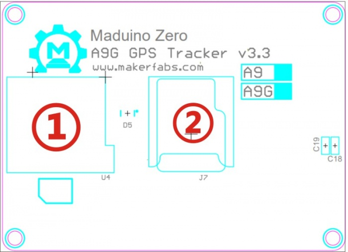
①Micro SIM Card Holder
②Micro SD Card Holder
Note: Maduino Zero A9G v3.3 either the battery or the Micro USB can be used for power supply. While Micro USB is connected, the board will be powered by MicroUSB first, while Micro USB removed, it will switch to battery automatically.
4. Usage
Warning: Don’t operate anything when the board supplied on (That is, plug or unplug the Antenna or Sensor, in case of short-circuiting that may burn the IC down.)
Note After a Arduino IDE installed, there is no package to support Maduino Zero(Arduino Zero ), we need to install the Arduino Zero package in Arduino IDE to continue.
Install Software for the Arduino/Genuino Zero The following steps show how to install software for the Maduino(Arduino/Genuino) Zero boards in the Arduino IDE.
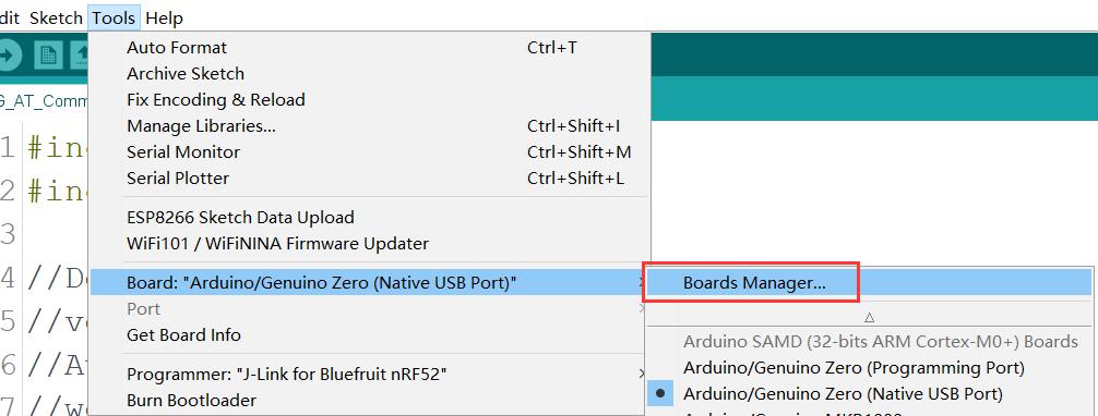
1.1. Open the Boards Manager From the top Arduino IDE menu, select Tools-> Board-> Boards Manager… to open the Boards Manager dialog box.
That is, install Arduino SAMD Boards(32-bits ARM Cortex-M0+)
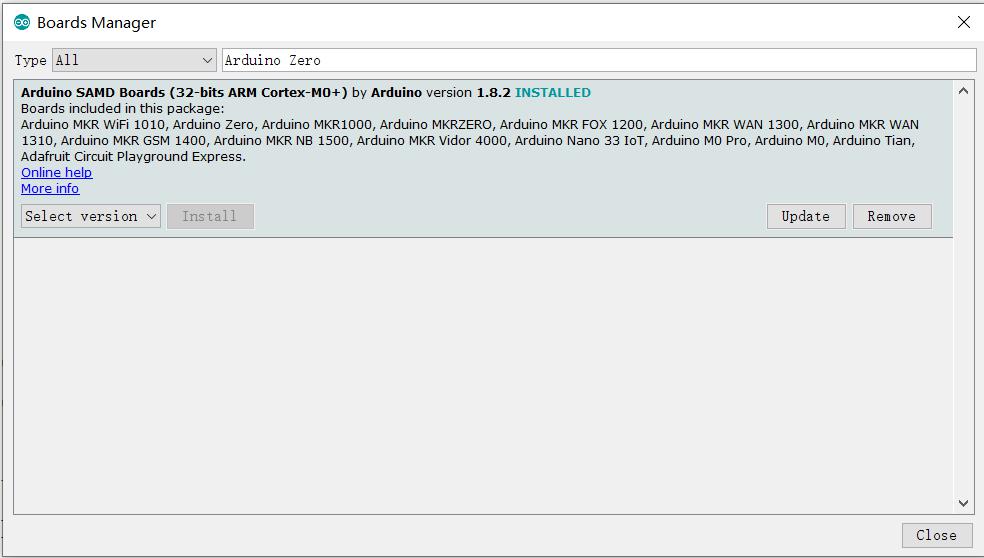
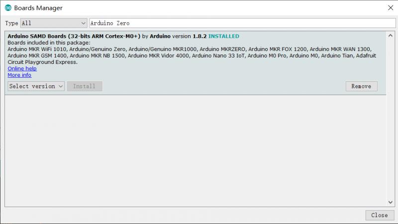
1.2. Select Arduino SAMD Boards and install in the Boards Manager dialog box, type Arduino Zero into the search field to easily find the Arduino SAMD package for 32-bits ARM Cortex-M0+ boards as shown in the image below. Install it.
1.3. Find the Arduino Zero Boards on the Arduino IDE Menu After the software package has been installed, the new Arduino boards can be seen on the Arduino IDE Board menu found under Tools →Board as shown in the image below.
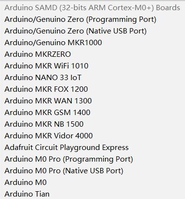
A new section called Arduino SAMD (32-bit ARM Cortex-M0+) Boards can be seen on the Board menu which contains Arduino M0, M0 Pro, Zero, MKR boards and others. This means the right package has been installed and Maduino ready to go.]
Hardware Connection
- Plug a MicroSIM card.
- Plug a GPS Antenna to designator which shows GPS.
- Plug a GSM Antenna to designator which shows GSM.
- Plug a Micro USB Cable to Maduino Zero A9/A9G.
- (Optional in v3.3)Plug a 3.7V lithium battery to J6
Note1: A 3.7V lithium battery normal voltage is 3.7V, but the range voltage often from 3.4V to 4.2V.
Note2: It can be powered by battery or the MicroUSB.
Note3: Both the battery or the MicroUSB can be used for power supply. While MicroUSB connected, the board will be powered by MicroUSB, while MicroUSB removed, it will switch to battery automaticly.
Program the Maduino Zero After open the IDE and turn the board on, select the desired Arduino/Genuino Zero(Native USB port) board from the Arduino IDE Board menu
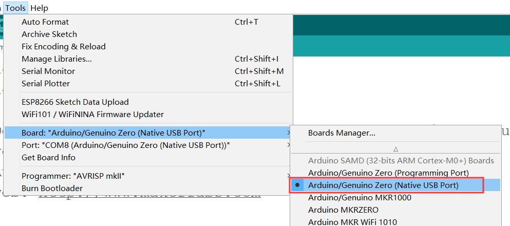
Then select the correct Port number from the menu item below Board on the Tools Menu. The Maduino board can now be programmed in the usual manner like Arduino.
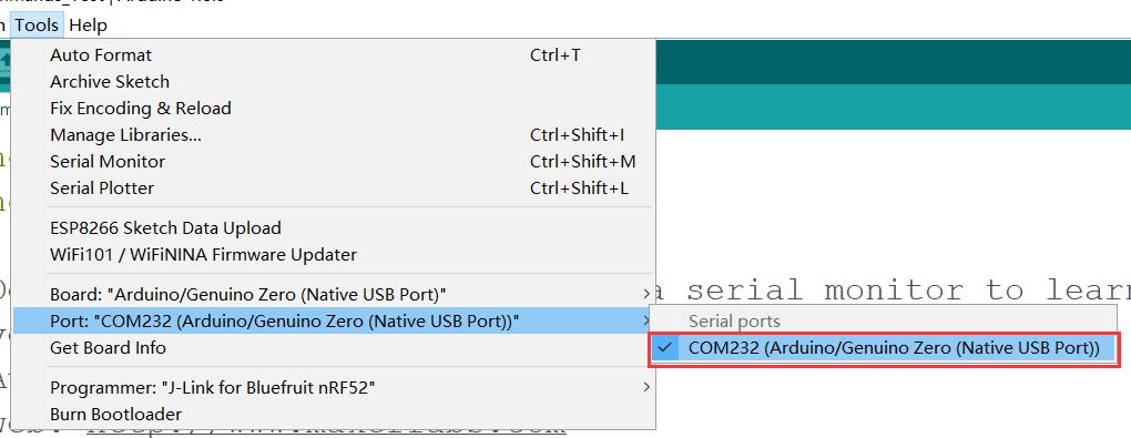
Note: It may show different Serial number in your PC. Select Arduino/Genuino Zero(Native USB port) Open our first programming code A9G_AT_Commands_Test.ino Click Verify button to compile it.
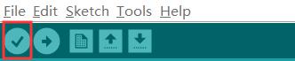
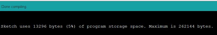
If there is no any errors, it will show Done compiling.
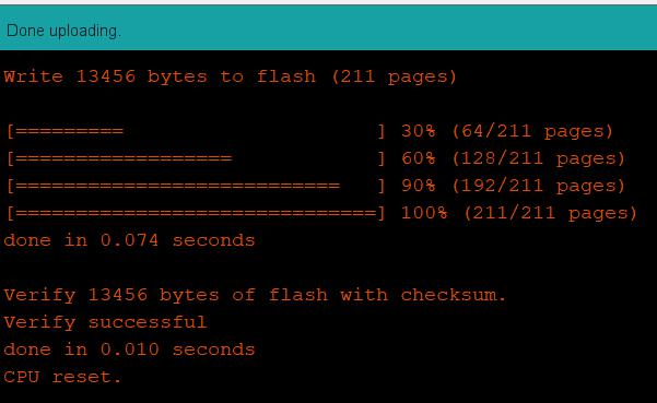
Click Upload button to upload firmware to the Maduino Zero A9/A9g board.
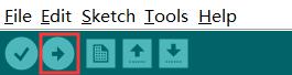
After done uploading, it will show the programming OK, as below:
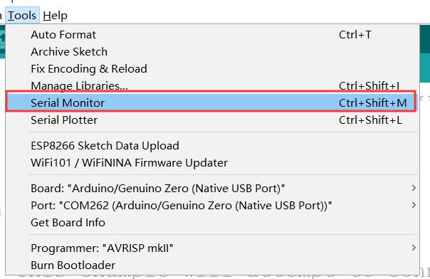
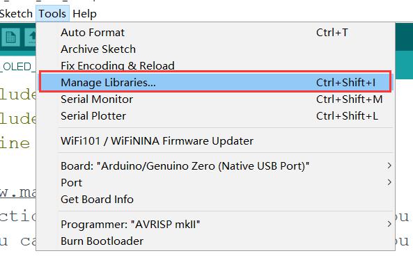
From the top Arduino IDE menu, select Tools → Serial Monitor… to open the Serial Monitor dialog box.
Select “Both NL & CR”, and baud rate 115200, it will show the board begin to work:
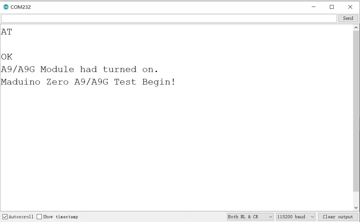
Click Send button after input AT and it will response OK. Now you can input other AT Commands refer to AT Command Set, Such as AT+CCID to show CCID, AT+CSQ to report GSM/GPRS signal quality, and so on. Thus you can learn much about A9/A9G Module that will be a great help to your next program.
How to get GPS Location information?
A9G Module is a GPRS/GSM+ GPS Quad-band module, with this board, we can use it as a GPS tracker, data acquisition, remote control and a lot of IoT projects or smart home projects. This example shows you how to get GPS location.
Attention: To get GPS location, please ensure you are outdoor, and plug in the GPS Antenna. Indoor may get the incorrect location or no location information.
(1) Turn on GPS, using the AT command “AT+GPS=1” to turn the GPS on:
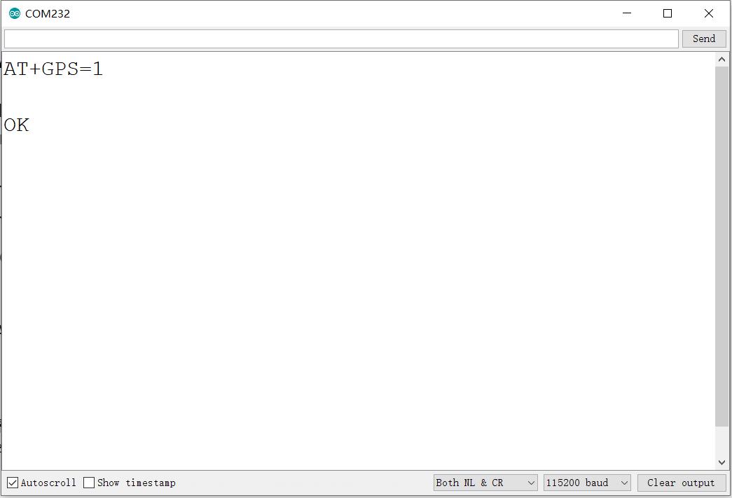
Note: The AT command “AT+GPS=0” to turn the GPS off.
(2) The AT command “AT+GPSRD=10” to read NEMA information every 10 seconds
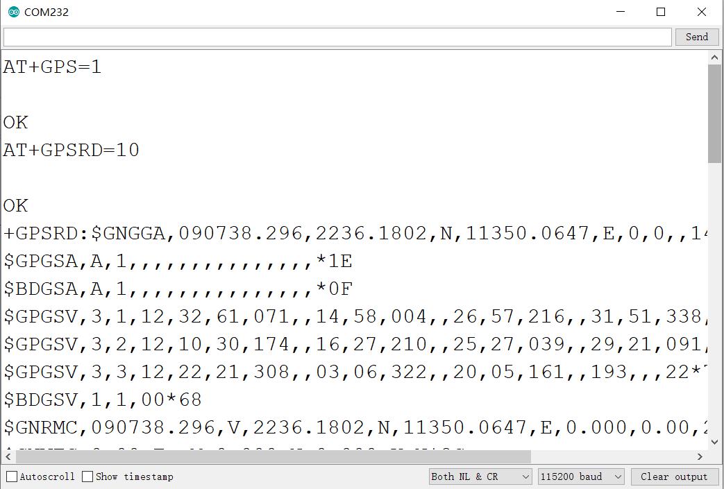
Note: It may take a while to report the location. Must be in the open air, can see the sky, otherwise you will not receive GPS signals.
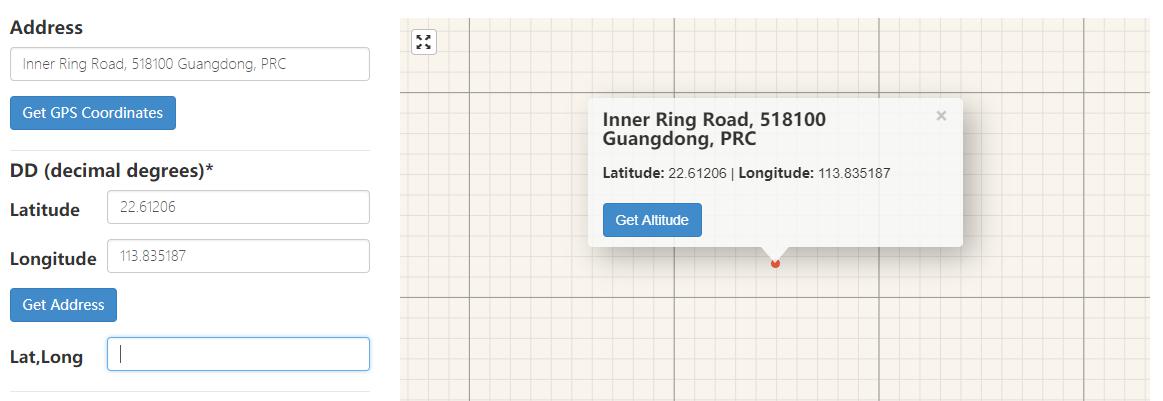
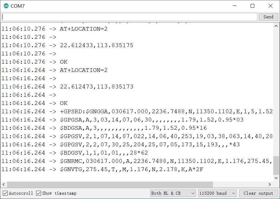
(3) AT+GPSRD=0 to stop the report and input AT+LOCATION=2 to get the GPS address
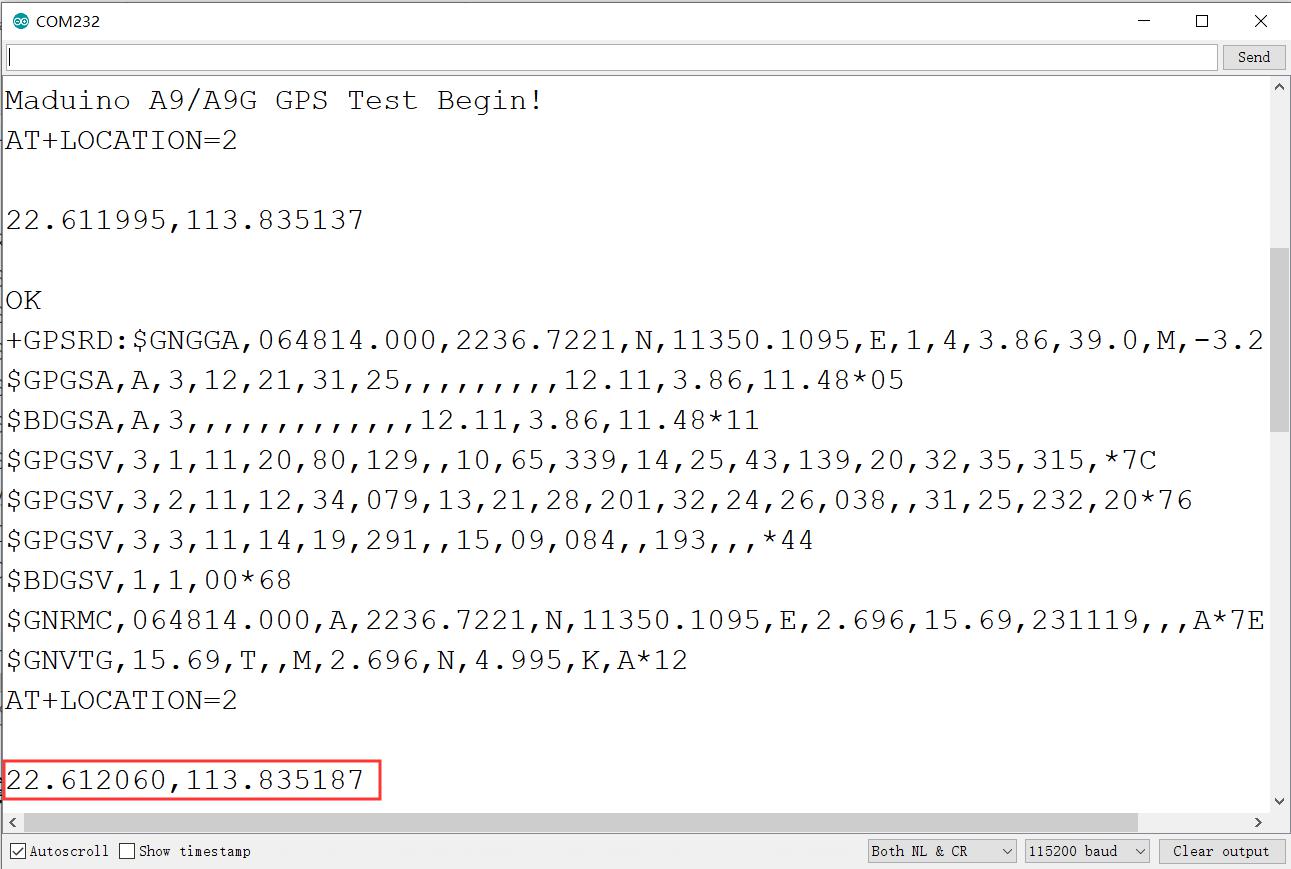
We can show our location where we are in https://www.gps-coordinates.net/
4.1 Maduino Zero A9G GPS Tracker Projects
Project_1: Shows the GPS location on OLED display
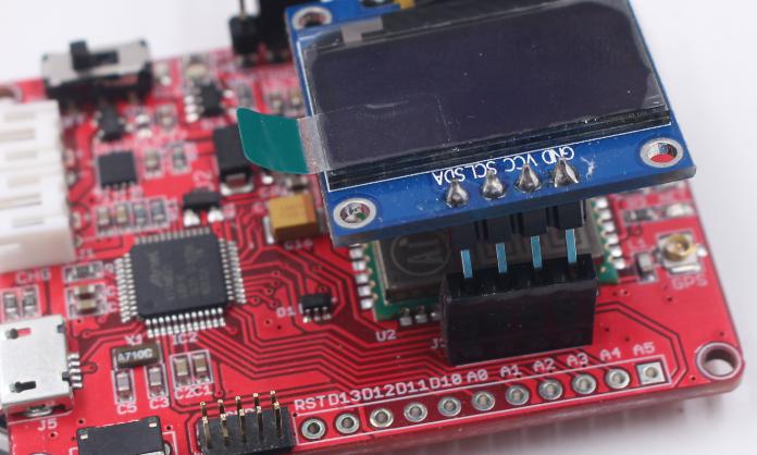
We need a 0.96"I2C OLED 128x64 at:
https://www.makerfabs.com/0.96-inch-i2c-oled-128x64-blue.html
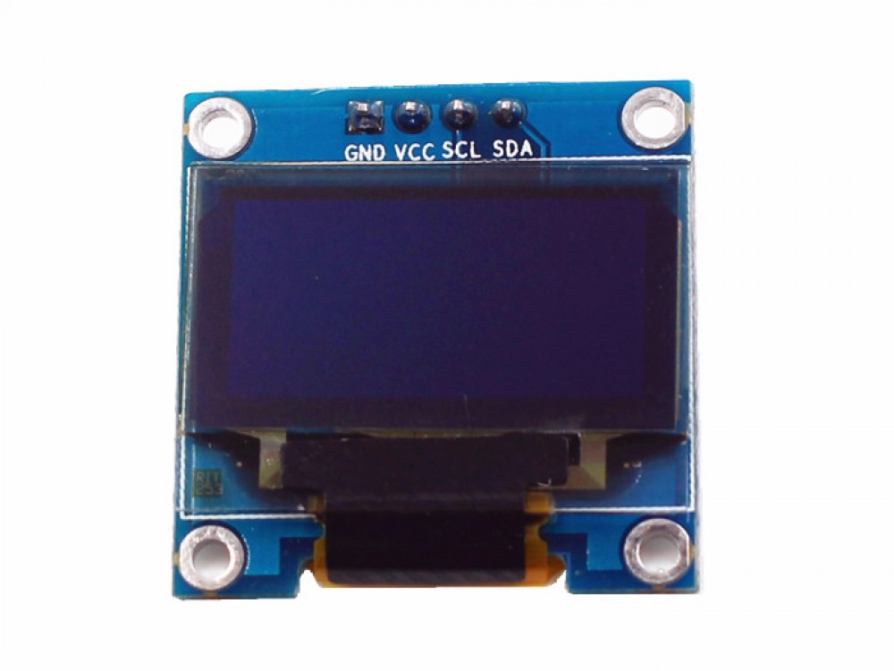
Check the Pin J3 on Maduino Zero A9G v3.3 (GND/3V3/SCL/SDA), as the pins definition compatible, plug the OLED directly on J3.
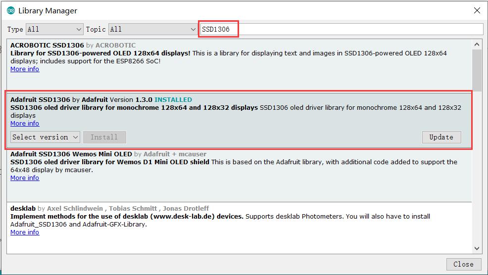
And install the SSD1306 OLED driver library
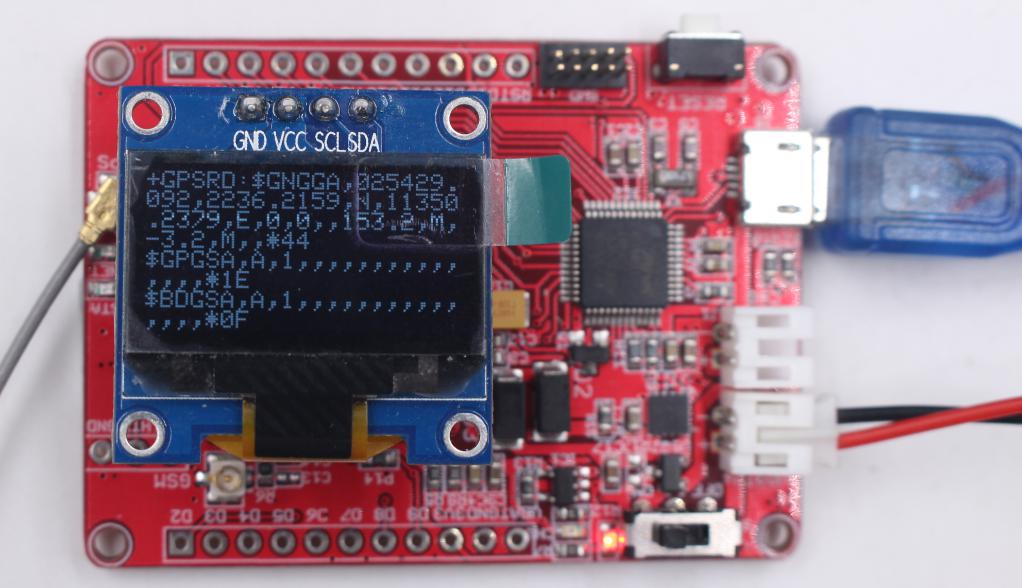
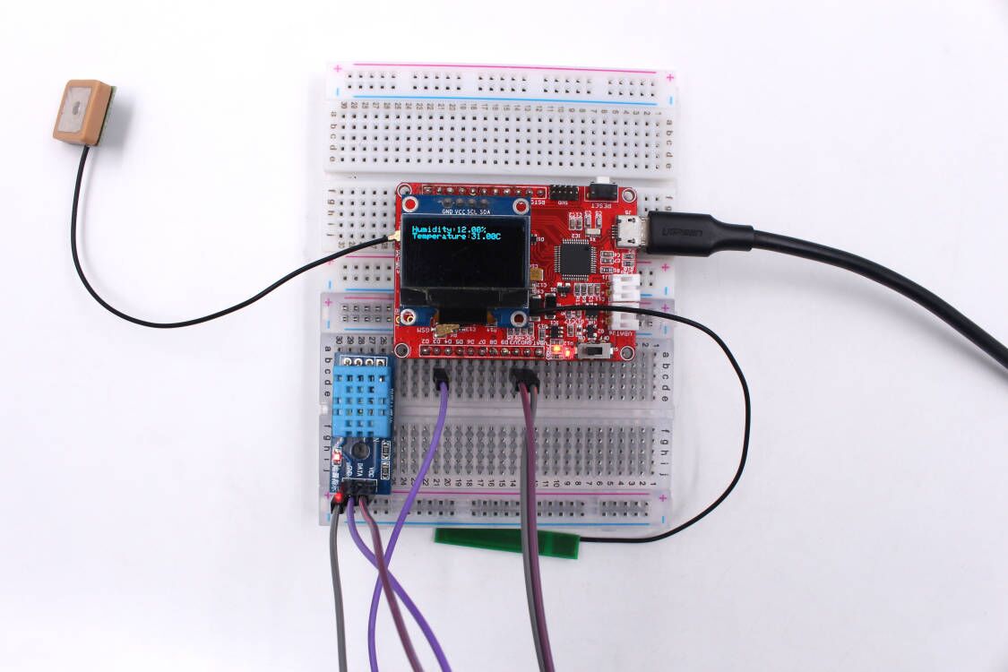
And then upload our example (A9G_GPS_OLED.ino) to Maduino board, the result shows the location on the OLED screen:
We also can save the GPS information into the SD card. Plug the SD card into the board, upload the demo code (A9G_GPS_SD.ino) to Maduino board, the GPS will be stored in the SD card.
And we can show the humidity and temperature on OLED screen too, Follow me to finish it.
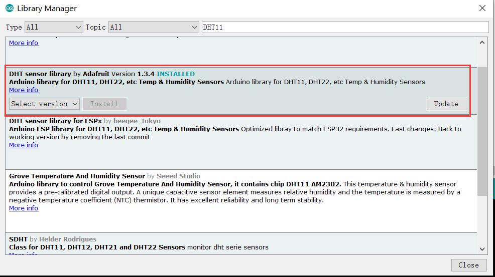
Install DHT library
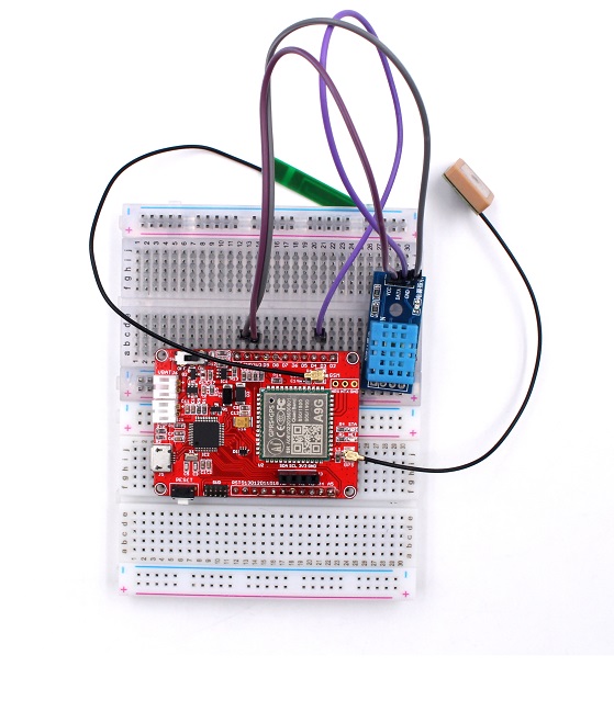
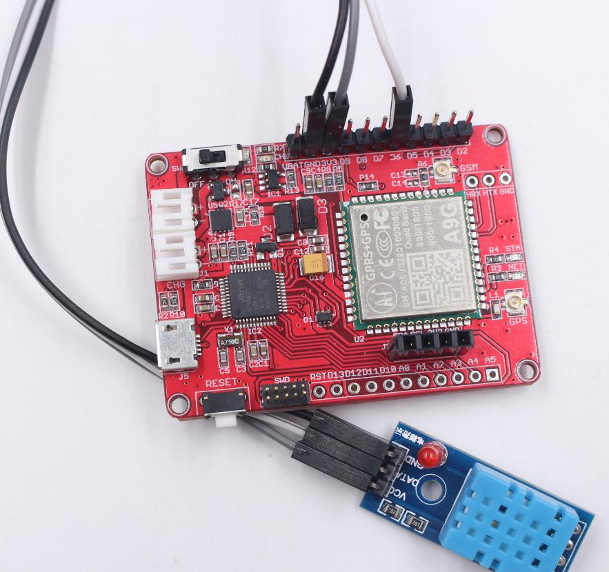
Hardware Connection
Connect the simple sensor to Maduino boards as following:
| Sensor | Maduino Pins |
|---|---|
| Sensor's GND | Maduino's GND |
| Sensor's DATA | Maduino's D6 |
| Sensor's Vcc | Maduino's Vcc |
Insert the I2C SSD1306 OLED:
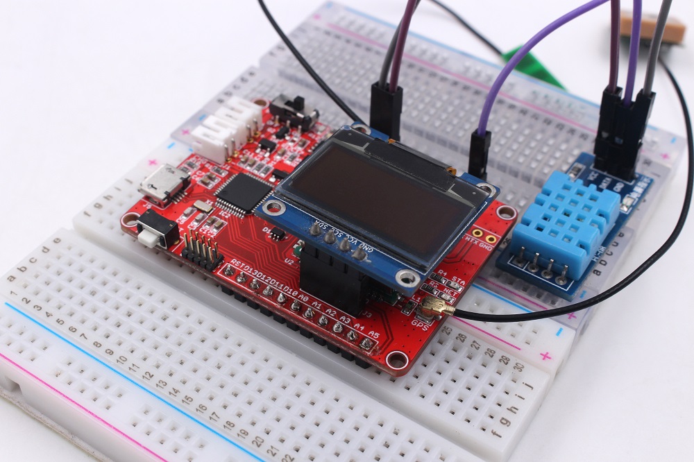
Upload the code A9G_DHT11_OLED.ino to the board. We can see the humidity and temperature on the screen.
Project_2: A Simple IOT Project- SMS Remote Control
Note that some fee maybe needed for each SMS depending on your local GSM Operator, make sure that the SIM Card is active, supports SMS and enough money left for this application.
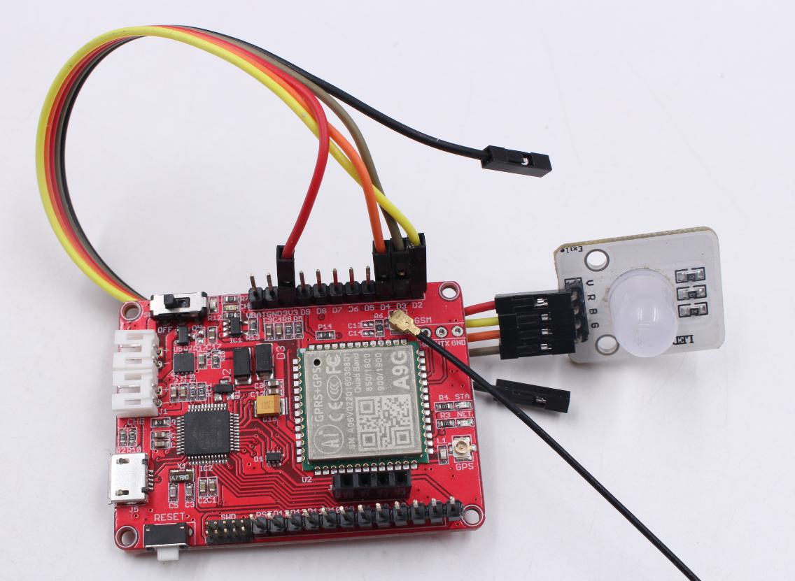
(1) Hardware connection Connect the LED to Maduino boards as follows:
| LED | Maduino Pins |
|---|---|
| Red PIN | Maduino's D2 |
| Green PIN | Maduino's D3 |
| Blue PIN | Maduino's D4 |
| Sensor's Vcc | 3V3 |
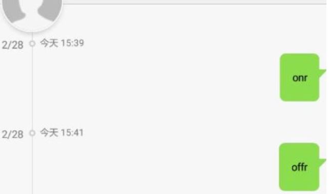
(2) Upload A9G_SMS_Control.ino to the board. Using your phone send a message to the SIM card you insert in board for turning on or turning off the led, such as ‘onr’ to turn the red led on, ‘offr’ to turn the red led off.
Supported messages in the code.
| Message | Result |
|---|---|
| onr | turn the red led on |
| ong | turn the green led on |
| onb | turn the blue led on |
| offr | turn the red led off |
| offg | turn the green led off |
| offb | turn the blue led off |
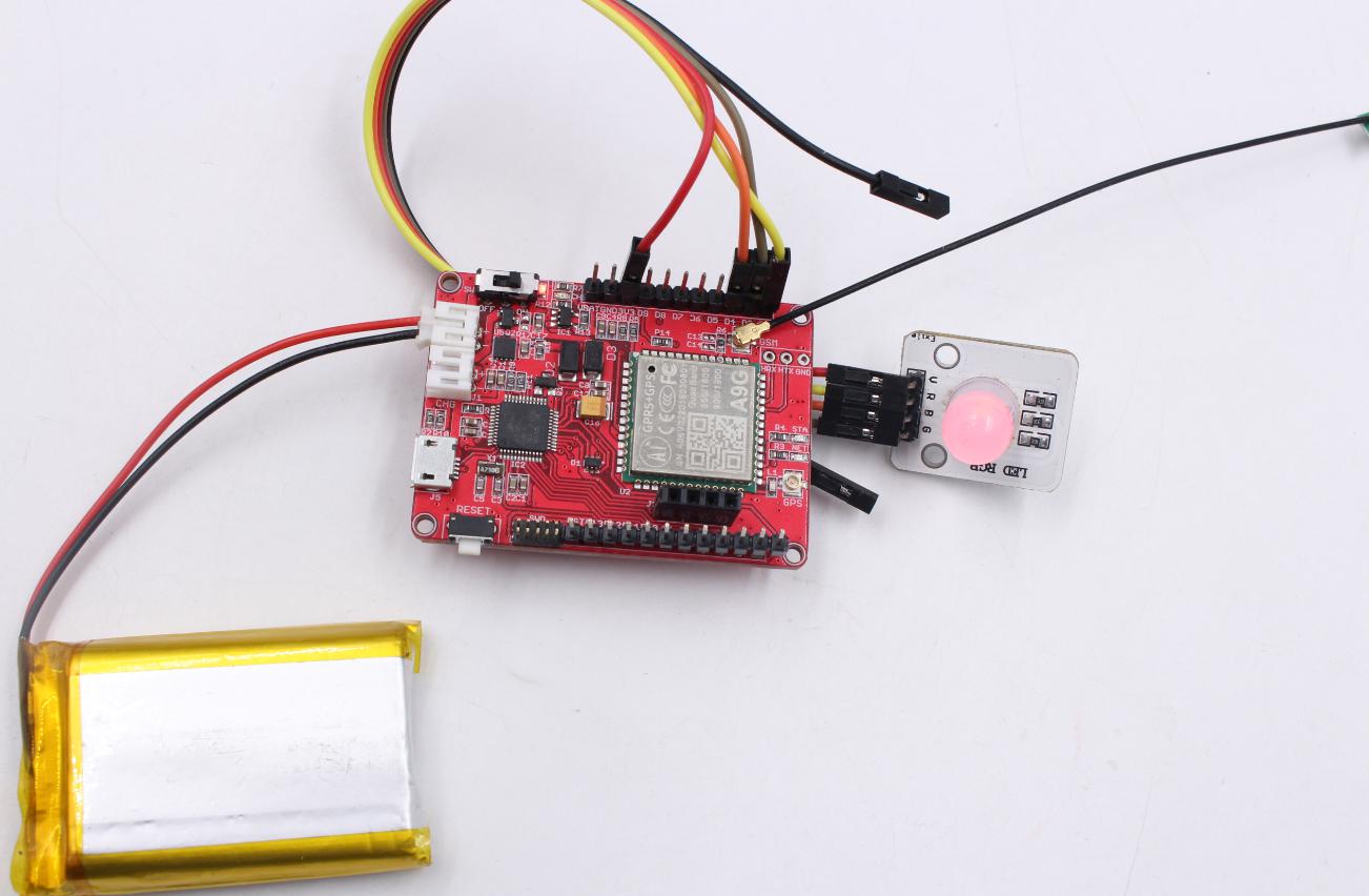
Then we can see the related LED on or off
Also, We can see the serial monitor shows the log when operate. That we can make sure the SIM card received a message.
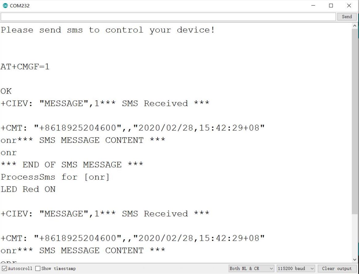
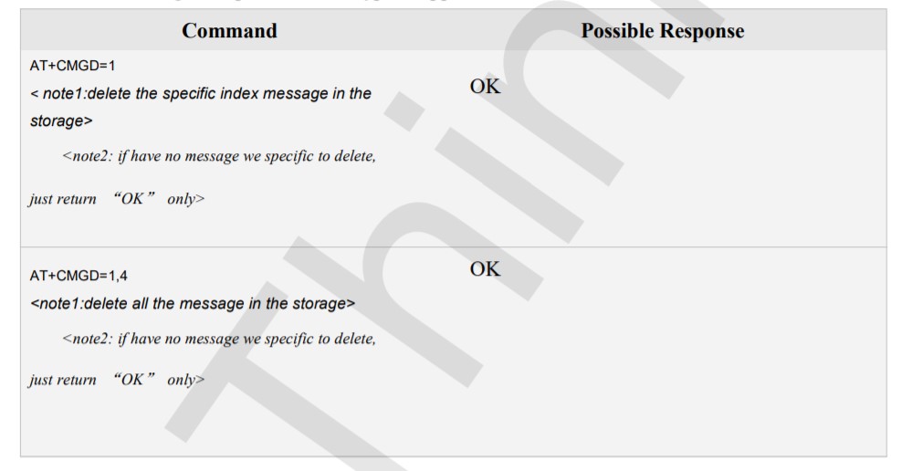
If your SMS messages fill in the A9G module, please send the command to delete them.
Project_3: A Simple IOT Project- Environment Remote Monitor
A9 or A9G Module is a GPRS/GSM+ GPS Quad-band module, with this board, we can use it as a GPS tracker, data acquisition, remote control and a lot of IoT projects or smart home projects. In this project, we will detect the humidity/temperature of our soldering lab, and reports it to internet thingspeak(https://thingspeak.com/channels/920821), so we can monitor the lab/home/office/farm environment remotely. We use the humidity /temperature sensor at:https://www.makerfabs.com/dht11-temperature-humidity-module.html
1.Sensor Connection
Connect the simple sensor to Maduino boards as following:
| Sensor | Maduino Pins |
|---|---|
| Sensor's GND | Maduino's GND |
| Sensor's DATA | Maduino's D6 |
| Sensor's Vcc | Maduino's Vcc |
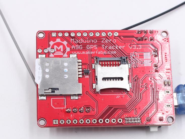
2.Insert a Micro SIM card and GSM antenna, power the Maduino with battery or MicroUSB. The Maduino Zero A9/A9G board uses the micro SIM card that is widely used in Android phone, install the Micro SIM card to the holder as below picture, and also the GSM antenna.
Note that some fee maybe needed for each SMS or GPRS depending on your local GSM Operator, make sure that the SIM Card is active and enough money left for this application.
3.Programming
3.1 Sign up an account in https://thingspeak.com/. If you already have one, sign in directly.
3.2 Click New Channel to create a new ThingSpeak channel.

3.3 Input name, Description, Select Field 1, Field 2, Field3, Field4.
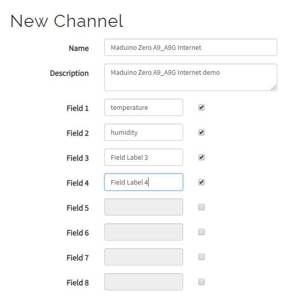
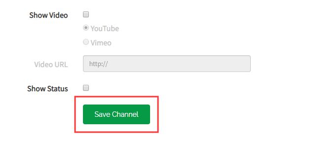
Note: Field 3 and Field4 are reserved for other applications. Then save channel on the bottom.
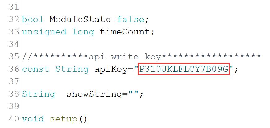
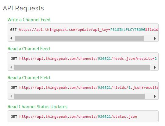
3.4 Copy your API Key, we will instead it in the code A9G_DHT_GSM.ino
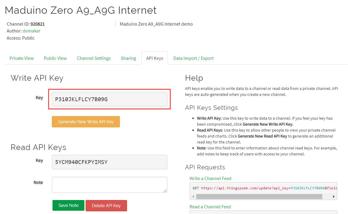
Below are some ways to use the API, what we used is Write A Channel Feed
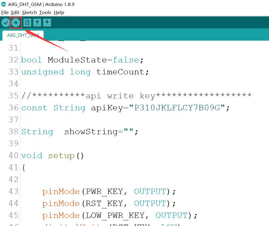
Select the right port and Arduino board: Arduino Zero(Native USB Port) to upload the code(A9G_DHT_GSM.ino) to Maduino Zero A9/A9G board
If the demo code runs successfully, you could refresh your channel on thingspeak.com to see the result. https://thingspeak.com/channels/920821
Have fun making Maduino!
You can get the code from our Github.
5. FAQ
You can list your question here or contact techsupport@makerfabs.com for technology support. Detailed descriptions of your question will be helped to solve your question.