Lora AC Dimmer
Introduction
An AC Dimmer is used to control the AC cycle Normally, a dimmer is used to turn the power ON/OFF for lamps or heating elements, it can also be used in fans, pumps, air cleaners, etc. Makerfabs Lora AC Dimmer chopper circuit is based on Triac BT139, and zero-cross checking circuit, it detects the zero-cross points and then the Triac controlled to chop the AC. Besides, to avoid the problem of AC can not be totally shunted off with Triac, a relay is implemented to make the AC totally On/Off. On-board AC/DC module implemented, so no external power supply needed, suitable for field applications. Makerfabs Lora AC Dimmer adjusts the AC cycle, suitable for applications that wireless control needed but without other wireless connections. Besides, the Wifi version, with ESP32, also available for customization. All Makerfabs products are totally Open Source for Makers.
Model:LOACDI01
Features
- ATMEL Atmega328P: High Performance, Low Power Atmel®AVR® Classic Microcontroller
- Speed Grade: 20Mhz
- Flash: 32KBytes
- RAM: 2KBytes
- EEPROM: 1Kbytes
- Onboard LoRa module
- Photocoupler, 400V peak off-state voltage
- 5V Controlled Relay(250VAC/10A, 125VAC/10A, 30VDC/10A, 28VDC/10A) for shutting off completely
- Fuse with 250V and 1.5A
- BT139X-600 Triac: max 600V/16A
- With integrated AC-DC Module
- With integrated Zero Crossing Detection(ZCD) for phase angle control or zero crossover
- With integrated RC snubber circuit design for TRIAC
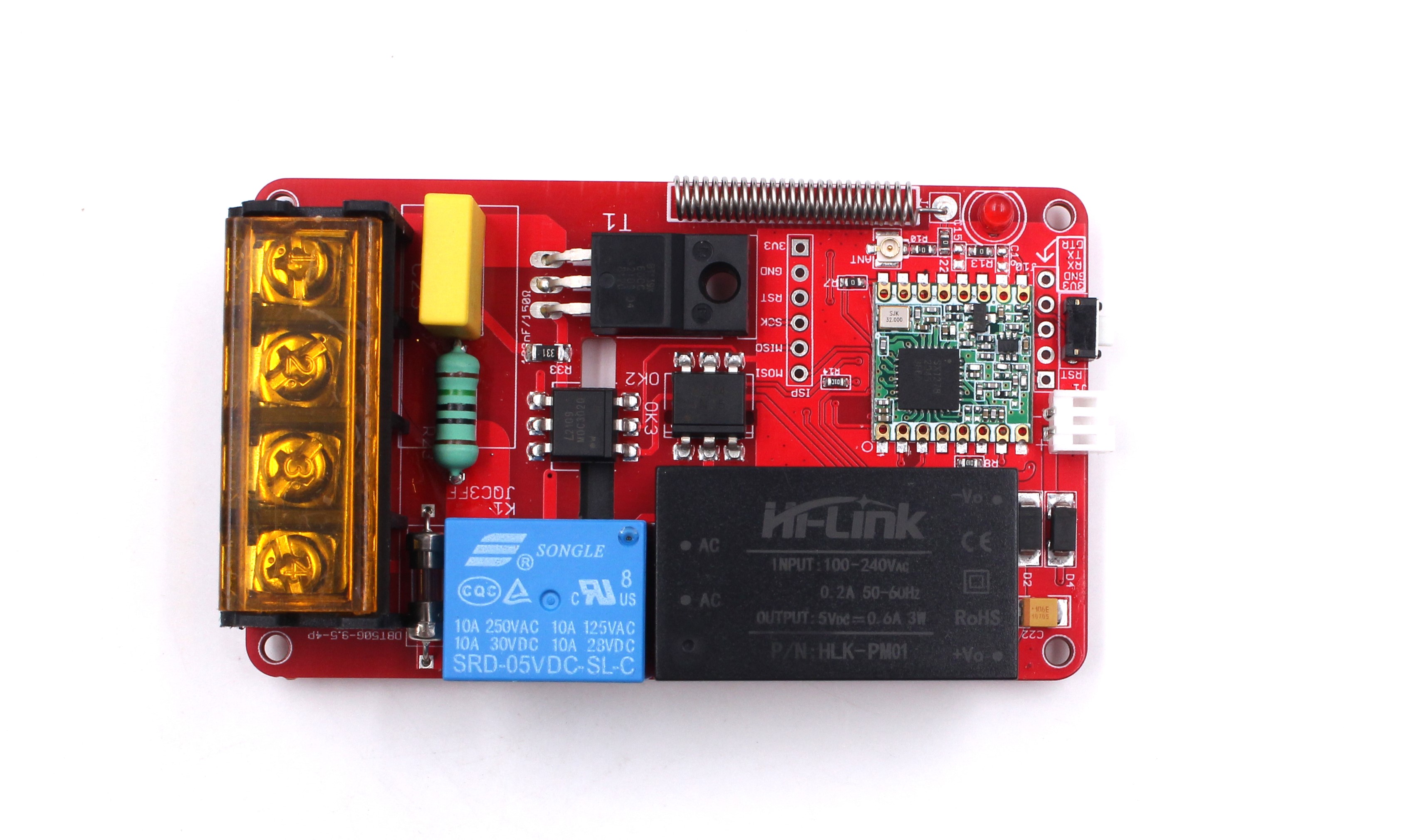
Hardware
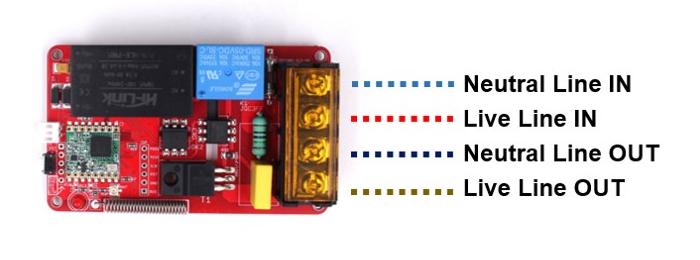
Interfaces
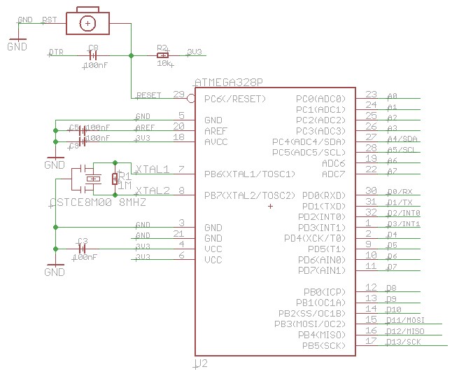
Schematic
- MCU circuit
LoRa Circuit
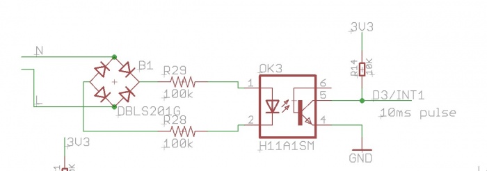
Zero crossing detection circuit
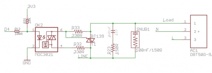
Control Circuit
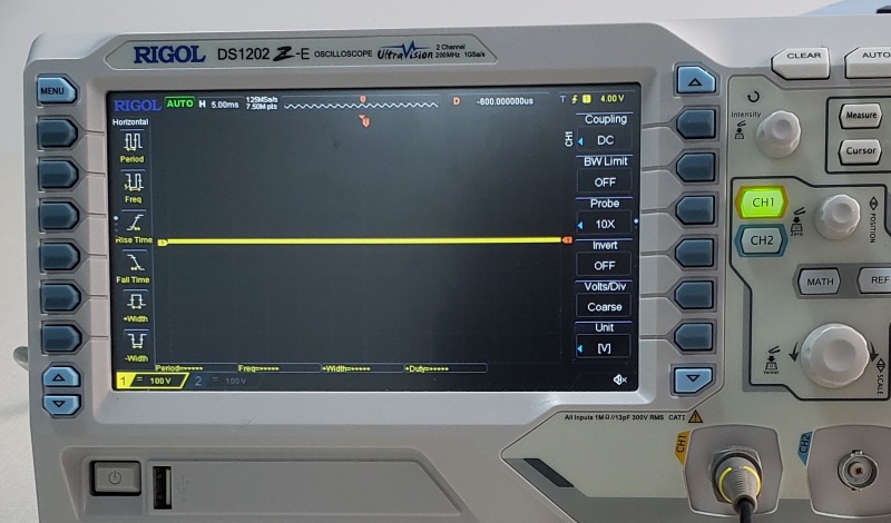
Singnal test
- Use the oscilloscope to check the output of AC dimmer.
1.When the MCU controls the dimmer to turn the output by 100%, the oscilloscope show:

2.Turn the output by 20%, the oscilloscope show:

3.Turn the output by 51%:

4.Turn the output by 83%:

- There is an onboard relay to shut off the dimmer completely. when the relay was off, the oscilloscope will show:
Firmware
Download
- LoRa AC Dimmer module has been uploaded the firmware before shipping, it does not require programming again. The firmware is available on GitHub.
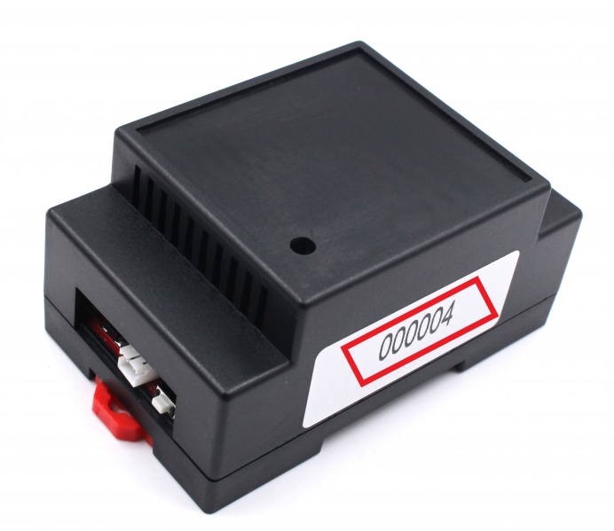
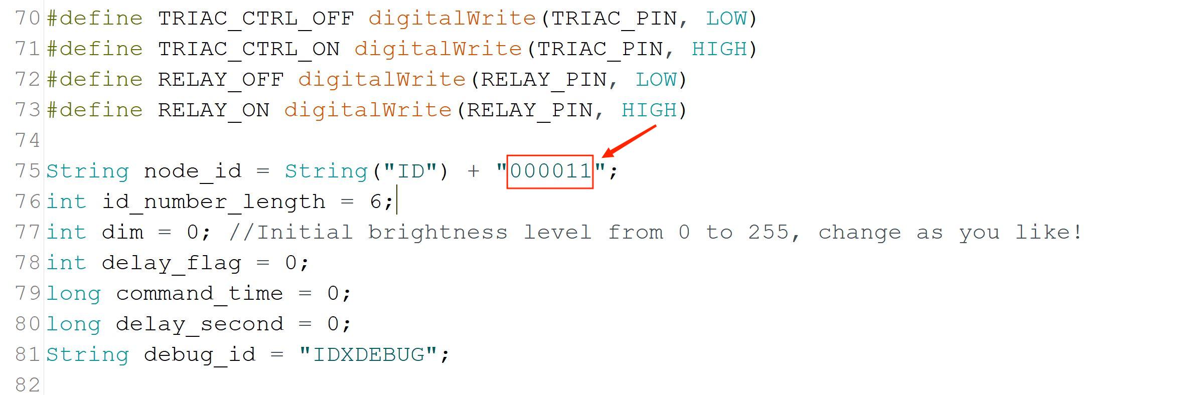
Device ID
- There is a serial number that Makerfabs coding it when the board was produced. The ID was made up of two words ("ID") and six digits ("000000"). Usually, the ID is printed on the PCB or case and you can see it clearly. As you see, each module has the only device ID for it which has been coded at the firmware.
Also the device ID can be changed if you want, modify the number to yours at the firmware, and upload the firmware to the board with Arduino IDE.
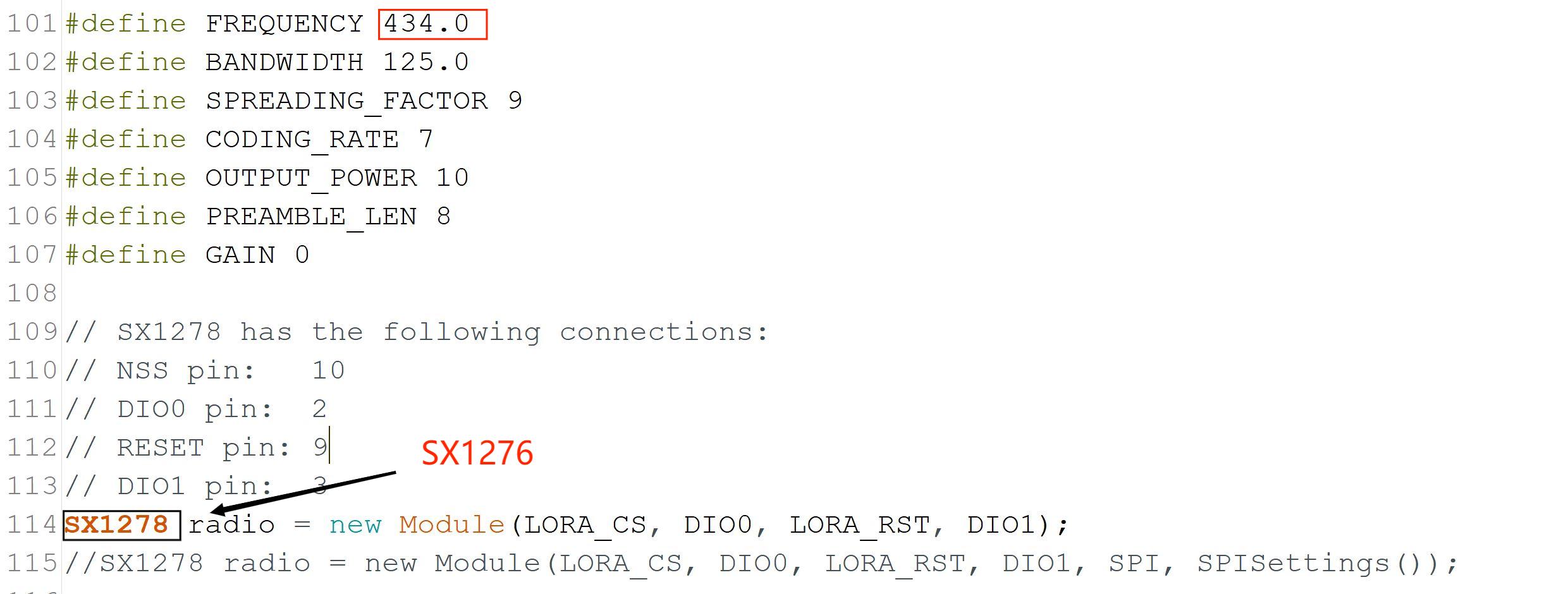
If the user selects 868MHz or 915MHz, the communication chip is different, and the communication frequency needs to be changed.
Instruction
- An instruction is composed of the three parts: Device ID, Action ID and Setting parameter.
Example: IDxxxxxxACTxxxPARAMxxxxxx#
Device ID: IDxxxxxx
Action ID: ACTxxx
Parameter: PARAMxxxxxx
The preceding zeros of every part must exist.
- Device ID
The device ID is used to identify whether the received instructions are needed.
- Action ID
There are five kinds of ID represented different operations: 000, 001, 002, 003, 004.
000: Turn off the relay and set the output by 0%.
001: Turn on the relay and set the output by 100%.
002: Turn on the relay and set the output by your setting.
003: Turn on the relay and set the output by your setting. Then hold it for the delay time you set and execute the 001 operation.
004: Turn on the relay and set the output by your setting. Then hold it for the delay time you set and execute the 000 operation.
- Setting Parameter
The setting parameter is composed of two parts: one is the delay time and another is the output. Each parameter is made up of three digits.
Example: PARAM005150#
Delay time: 005 ==> 5S (the range is 0 - 999)
Output: 150 ==> 59% (the range is 0 - 255)
- Example E: ID000032ACT001PARAM000000# R: The dimmer named 000032 will be turned on, and set the output by 100%. E: ID000032ACT003PARAM007051 R: It will set the output of the dimmer by 20% and hold it for 7 seconds, then turn the output by 20%.
Using Demo
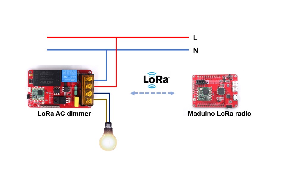
Overview: Use the Maduino LoRa Radio board as the LoRa terminal to control the light connected with the AC Dimmer remotely.
- LoRa AC dimmer module does not require to program again, just remember the ID for the specified instruction.
1.Connect the light to the screw terminals of the output, plug the Live line and Neutral line into the input. Please note that all operations must be on the power cutting off. 2.Power on the LoRa AC dimmer.
- Program the Maduino LoRa radio board to be the controller by Arduino.
1.You can get the demo code from here.
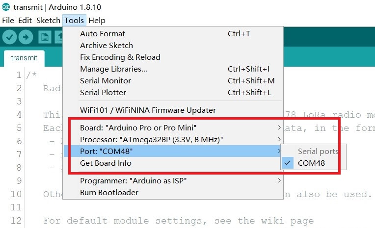
2.Open the demo code with Arduino IDE.
3.Select the development board (Arduino Pro Mini) and the port.
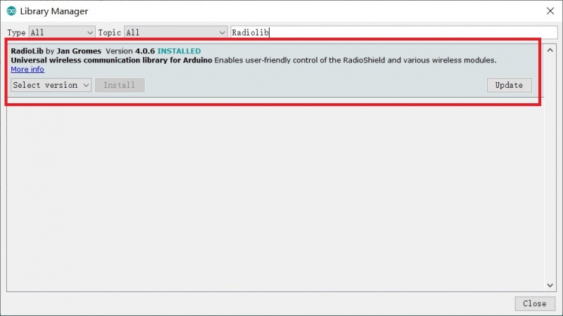
4.Install the library (RadioLib.h) for the LoRa module driver.
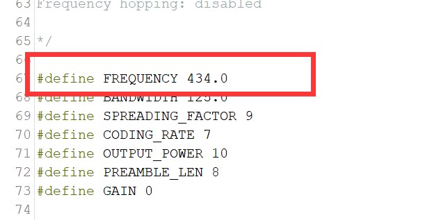
5.Remember to modify the LoRa frequency to your modules at the code.
5.Remember to modify the LoRa frequency to your modules at the code.
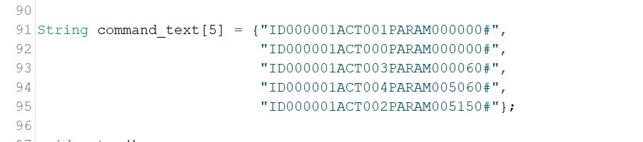
String command_text[5] = {"ID000032ACT001PARAM000000#",   //Control the dimmer to turn on the relay and output 100%
                          "ID000032ACT000PARAM000000#",   //Control the dimmer to turn off
                          "ID000032ACT003PARAM000060#",   //Control the dimmer to turn on the relay and output 23% (60/256)
                          "ID000032ACT004PARAM005060#",   //Control the dimmer to turn on the relay and output 23% (60/256), and hold it for 5s,then turn off the relay
                          "ID000032ACT002PARAM005150#"};  //Control the dimmer to turn on the relay and output 58% (60/256)
7.Verify the code and upload it to the board.
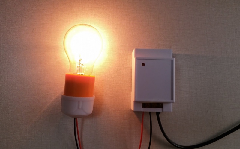
- Power on the Maduino LoRa radio board. When it transmits the command "ID000032ACT001PARAM000000#", the dimmer which ID is 000032 will turn on the relay and set the output by 100%.
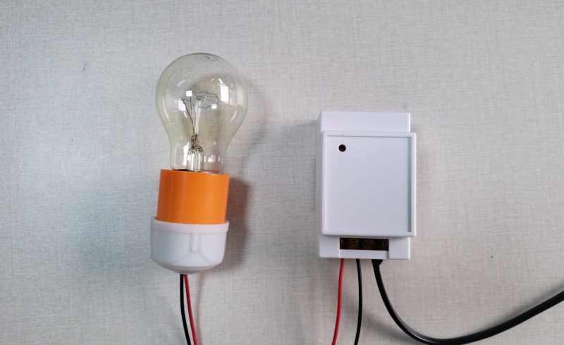
- When it transmits the command "ID000032ACT000PARAM000000#"The dimmer which ID is 000032 will turn off the relay and set the output by 0%.
-
When it transmits the command "ID000032ACT002PARAM005150#"The dimmer which ID is 000032 will turn on the relay and set the dimmer output by 58%.
-
Show

FAQ
You can list your question here or contact techsupport@makerfabs.com for technology support. Detailed descriptions of your question will be helped to solve your question.