Matouch 1.28 ToolSets
1. Introduction
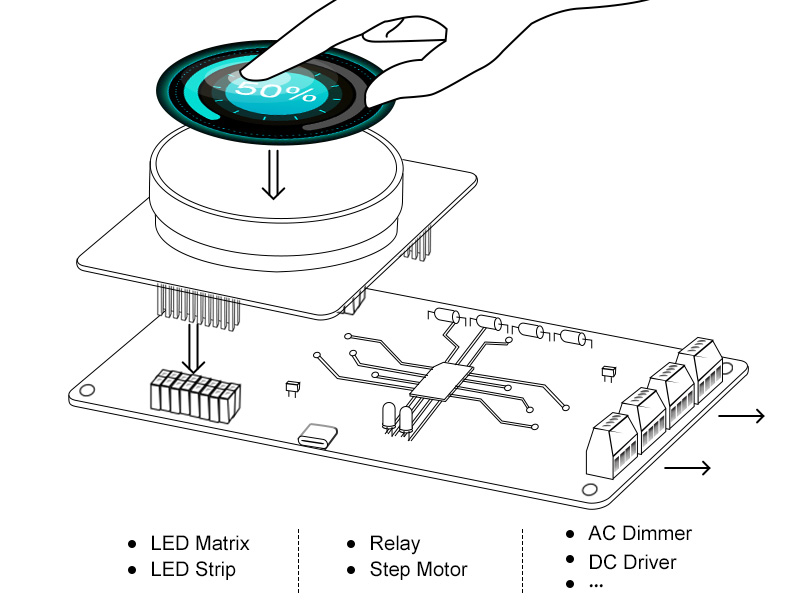
MaTouch 1.28” ToolSets are series of ESP32-based products mainly consist of MaTouch 1.28” controller and kinds of functional expansion such as Dimmer/ Relay Controller/ Motor Driver, etc. It’s designed as tools to control/drive these actuators directly while also keep open hardware/software, which make it possible for users’ remaking and integration to other field projects.
2. How to use?
2.1 Preparation
The Matouch 1.28 DevKit includes a controller and six functional kits, each designed to work in conjunction with the controller. To get started, you'll need one controller and at least one functional kit of your choice.
2.2 RGB Matrix Panel Driver
Hardware preparation:
- MaTouch 1.28" Dev_ESP32S3 Controller
- MaTouch 1.28" Dev_RGB Matrix Panel Driver
- 64x64 RGB LED Matrix
- SD card
- 5V 6A Power Adapter
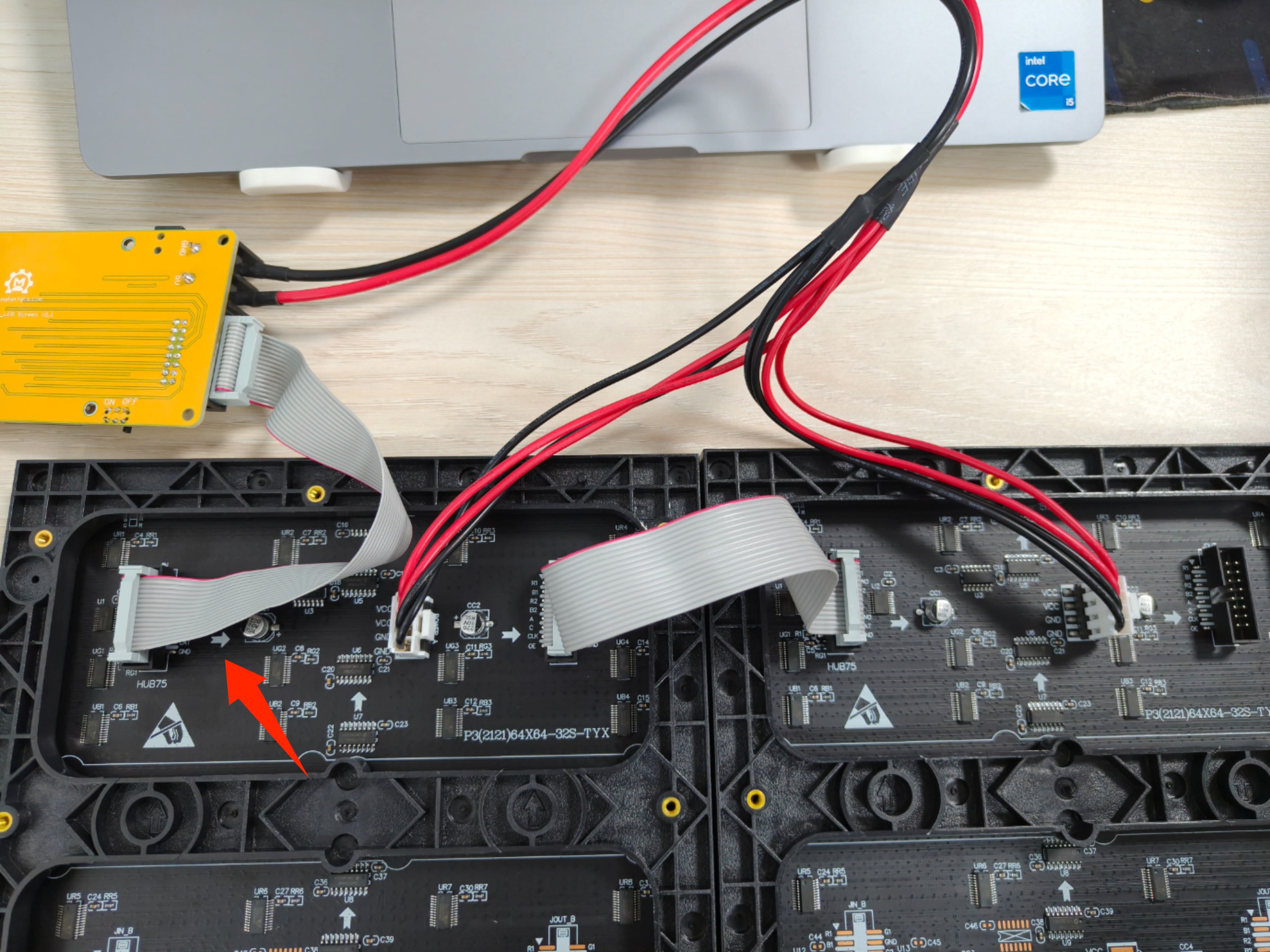
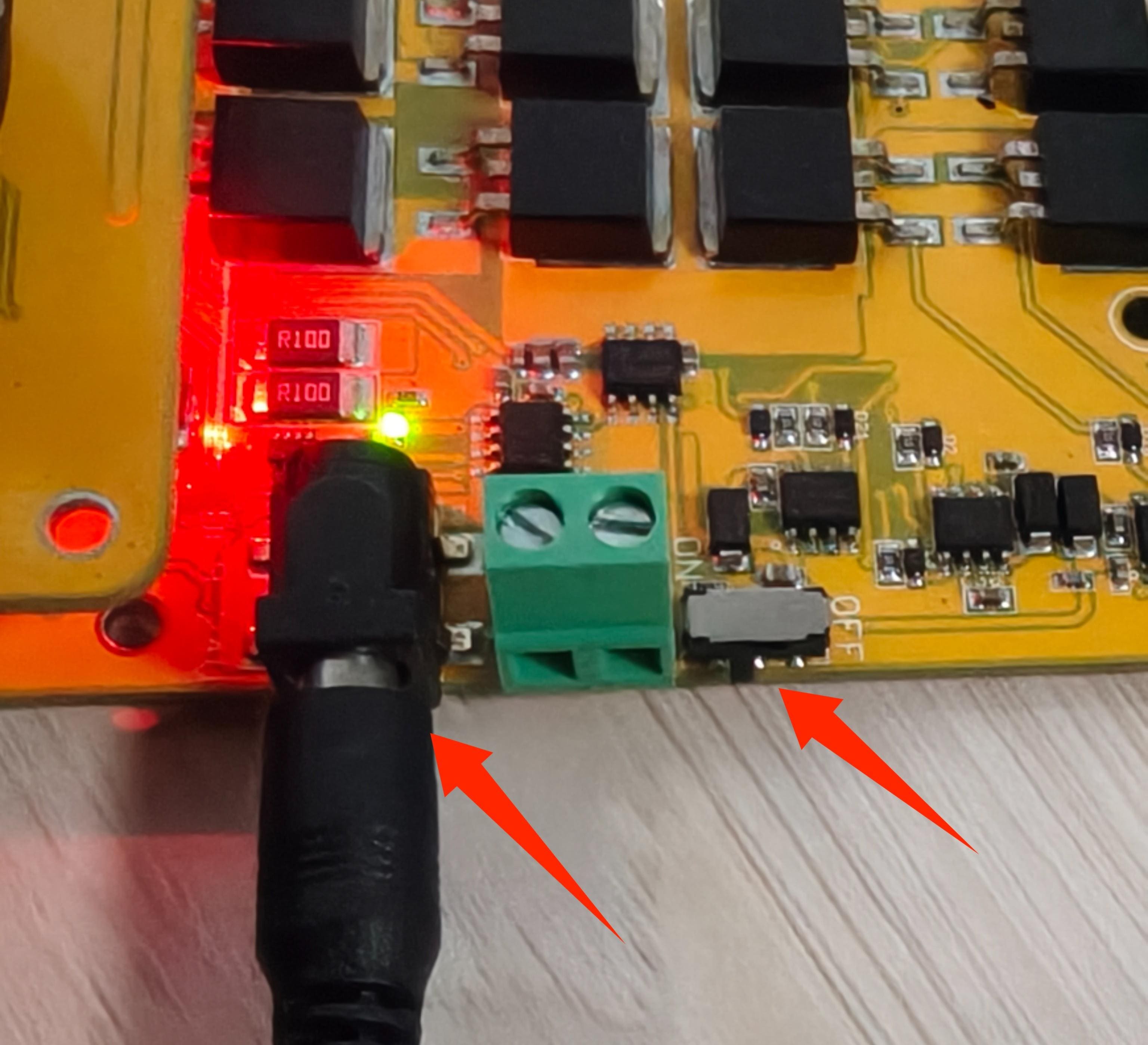
1.Use the cable to connect the left side of the arrow to the expansion board. The red wire is connected to the 5v of the expansion board, and the black wire is connected to the GND of the expansion board.
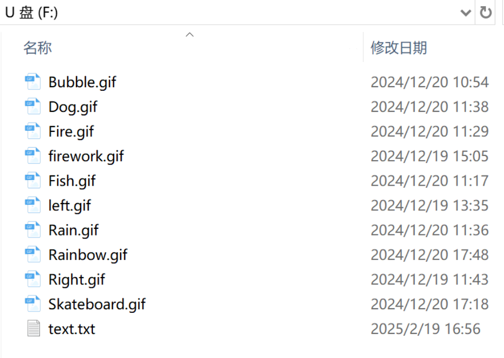
2.Save the file you want to display into the SD card, then insert the SD card into the controller.
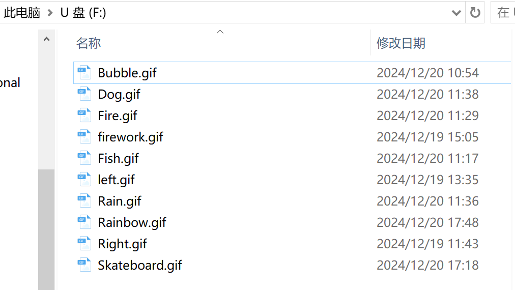
If you just need to test it, you can download the gif from here.
Note: You can only save in the first directory, you can't create a folder to save in.
Currently only supports gif and txt files, if you want to display other, you need to modify the programme yourself.
When you want to save your own files, the length of the files must be 64 * n, the width must be 64.
For example, if you connect only one RGB Matrix Panel, your files must be 64 * 64, and if you connect two, it will be 128 * 64.
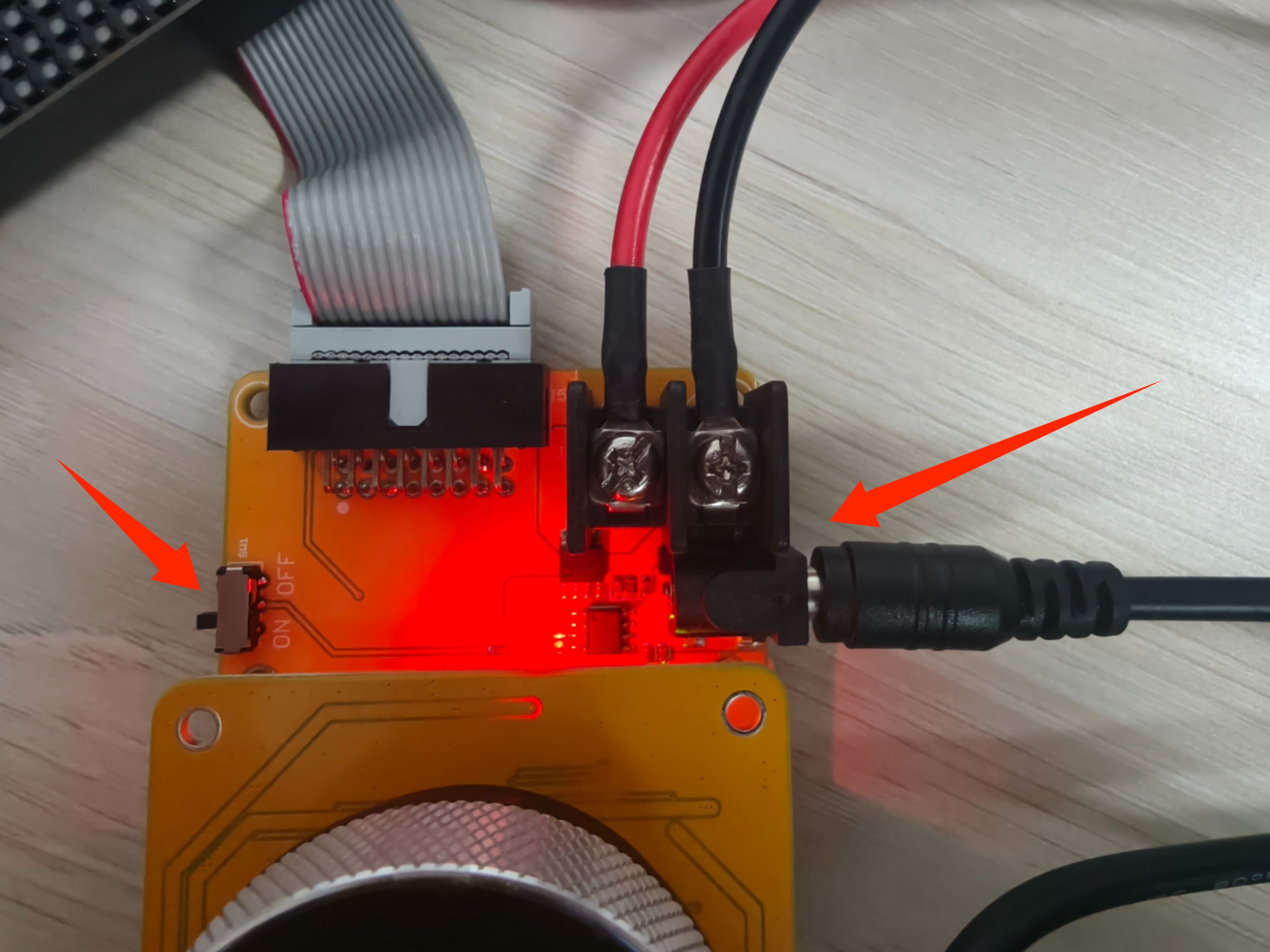
3.Connect to the expansion board using the 5V 6 A power adapter and toggle the switch to the ON label.
Usage:
This RGB Matrix Panel has two functions: switching GIF images and brightness adjustment.
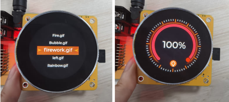
1.You will see the name of the gif file you have stored in the sd card, and you can rotate the encoder to switch the GIF or txt files.
2.Slide the screen left to switch to the interface of adjusting the brightness, which can be adjusted by rotary encoder.
2.3 RGB LED Strip Driver
Hardware preparation:
- MaTouch 1.28" Dev_ESP32S3 Controller
- MaTouch 1.28" Dev_RGB LED Strip Driver
- Two LED Strips
- Power supply with PD function
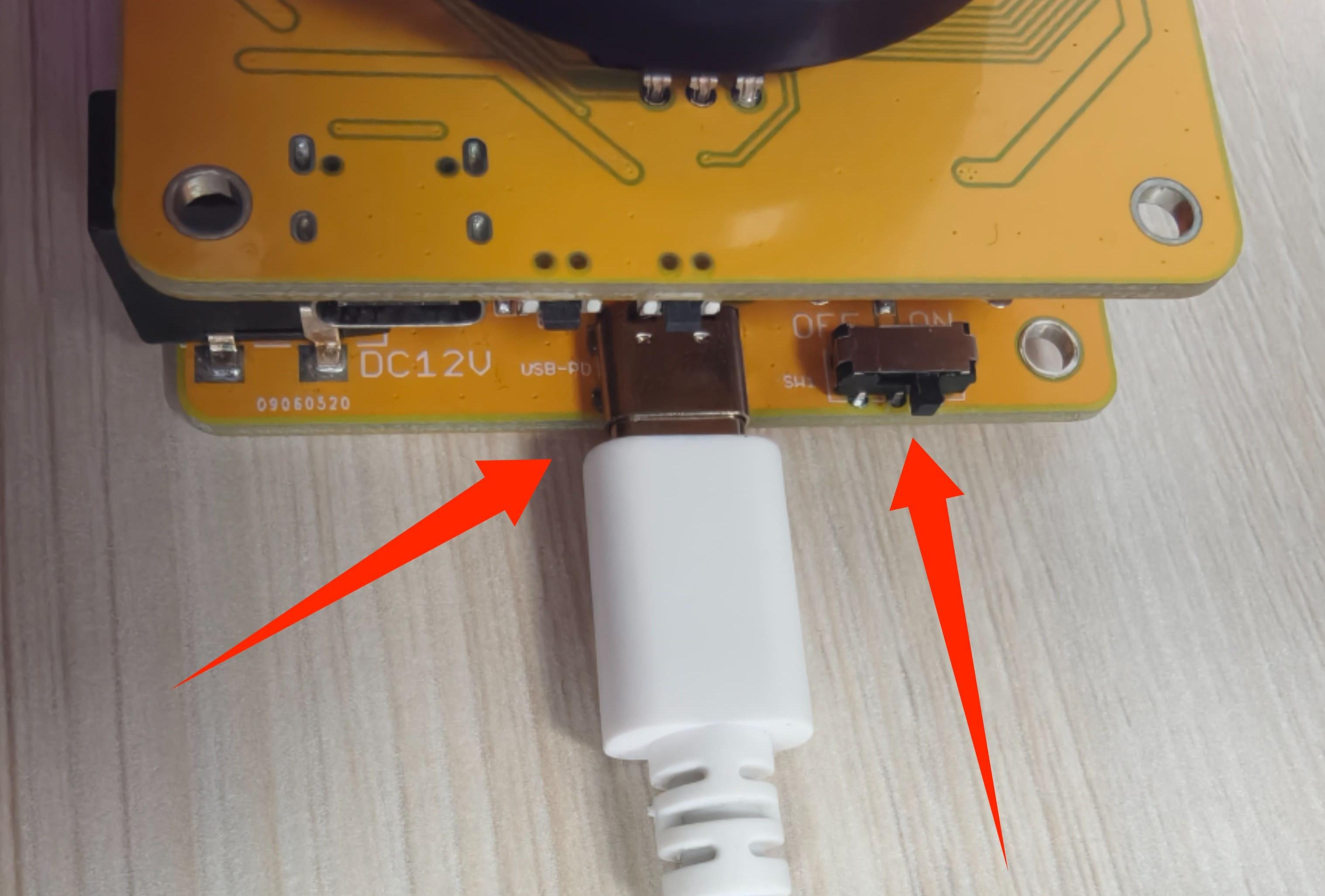
1.Connect the Power Cord to the Expansion Board.
2.Connect the LED strip to the adapter cable, then connect it to the expansion board according to the table below.
| RGB LED Strip Driver | Strip light |
|---|---|
| VCC | Red wire |
| GND | Yellow wire |
| IO7 | Black Wire |
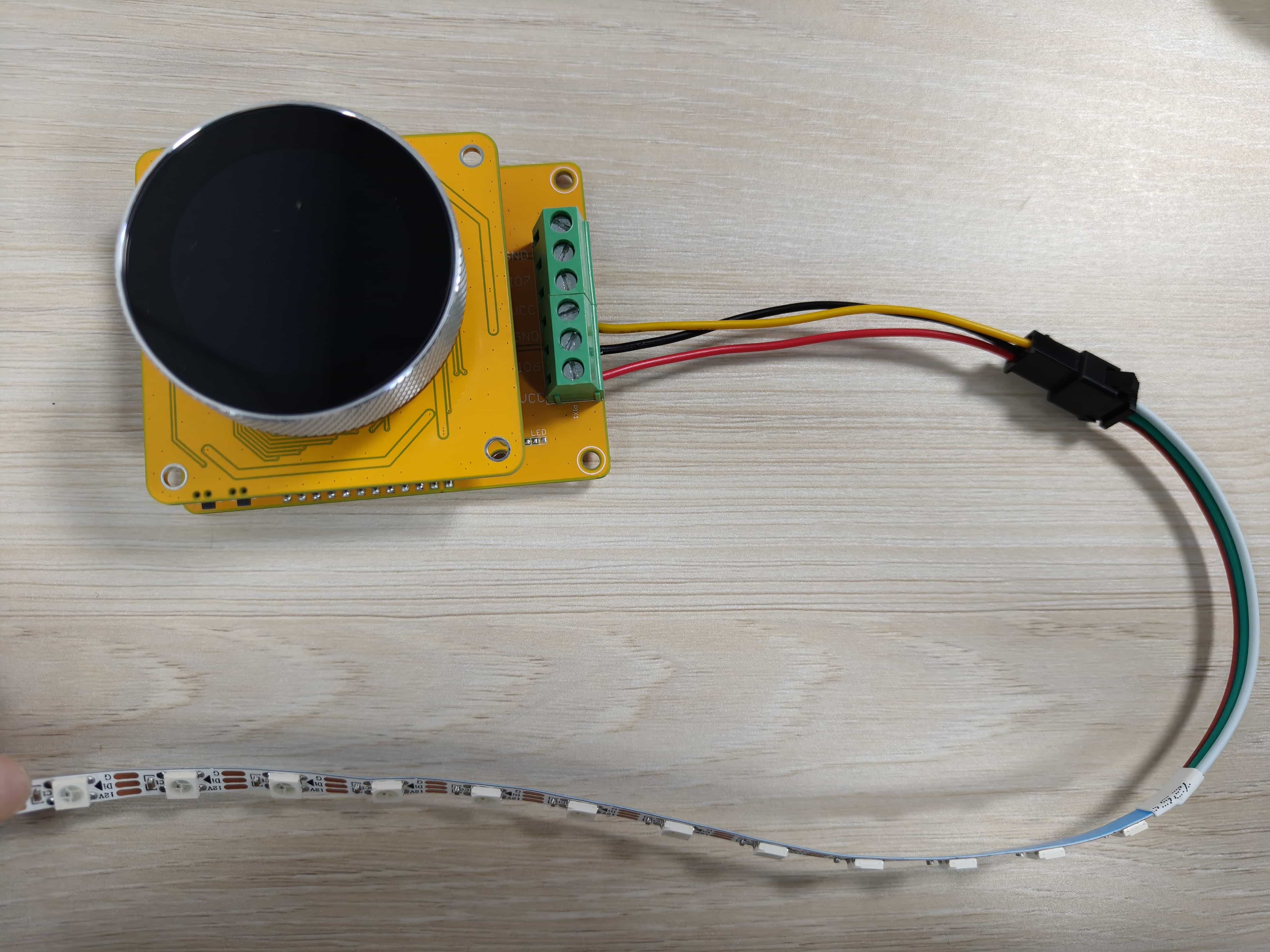
3.Another LED Strip in the same way.
4.Connect the expansion board with a PD-capable power supply and toggle the switch to the ON label.
Usage:
This RGB LED Strip Driver has the following functions:
- Adjustment of supply voltage
- Adjust the number of light strips
- Adjust the brightness of light strips
- Adjust the color of light strips
- Adjust the mode of light strips
- Adjust the frequence of light strips
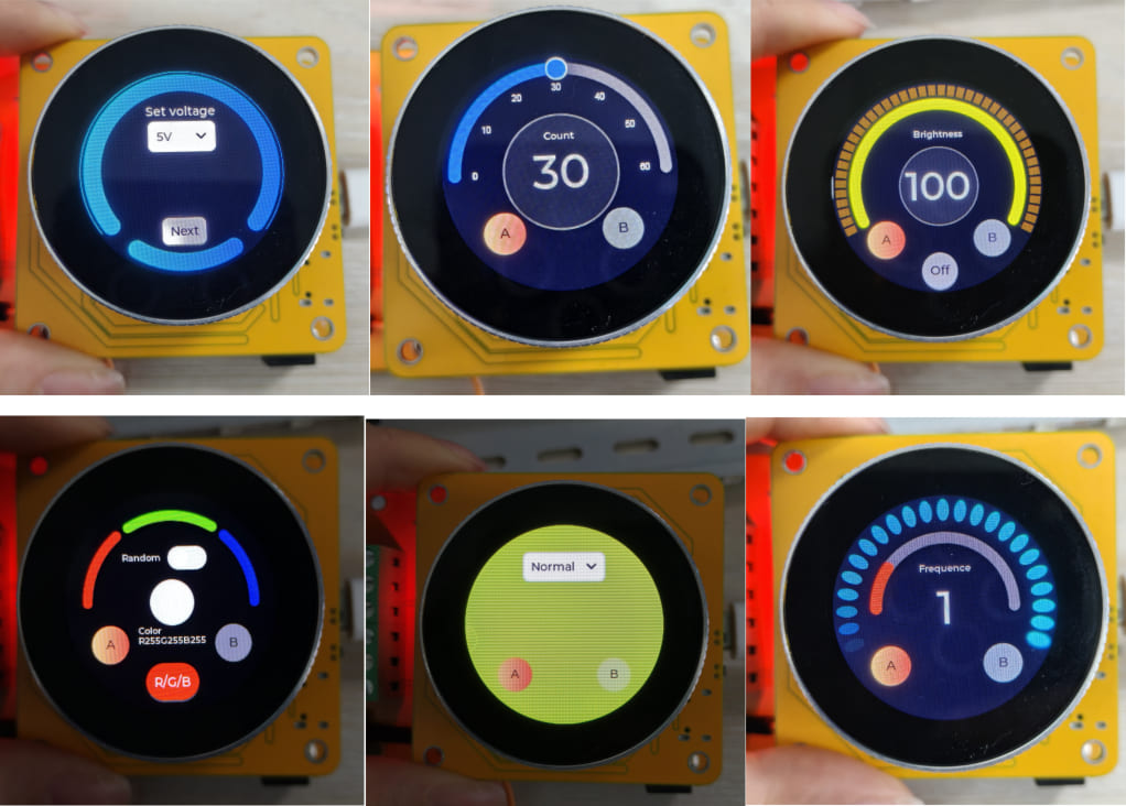
1.Set supply voltage
Since the power supply voltage of the strip is 5V, so we select 5V and click the Next button.
- Drop-down selection box to select the voltage---5V, 9V, 12V.
- The next button determines the selected voltage and goes to the function page.
The following function pages can be switched by swiping the screen left or right.
2.Set the number of light strips
The initial value of the number is 30.
- The number of light strips can be changed by knob.
- Click the A or B button to switch the light strips and adjust their number accordingly.
3.Set the brightness of light strips
The initial value of the brightness is 100.
- The brightness of light strips can be changed by knob.
- Click the A or B button to switch the light strips and adjust their brightness accordingly.
- Click the off button to set the brightness of strip directly to 0.
4.Set the color of light strips
The initial value of the color is white. The colour circle in the middle of the screen will show the actual RGB composite colour.
- The RGB color of light strips can be changed by knob.
- Click the R/B/G button to switch R or G or B colour channels.
- Click on the Random button to make the light strip randomly generate different colours.
- Click the A or B button to switch the light strips and adjust their color accordingly.
5.Set the mode of light strips
The initial of the mode is Normal. Normal is always on, Flow_1 is the light strip flowing to the right, Flow_2 is the light strip flowing to the left.
- Drop-down selection box to select the mode---Normal, Blink, Flow_1, Flow_2.
- Click the A or B button to switch the light strips and adjust their mode accordingly.
6.Set the frequence of light strips
The initial value of the frequence is 1. The higher the frequency, the faster the strip flashes and the faster the strip flows.
- The frequence of light strips can be changed by knob.
- Click the A or B button to switch the light strips and adjust their frequence accordingly.
2.4 Relay with 8 channels
Hardware preparation:
- MaTouch 1.28" Dev_ESP32S3 Controller
- MaTouch 1.28" Dev_8 Channel Relay
- 12V Power Adapter
- 220V power supply
1.Relay needs to be connected to external devices, here take lamp as an example. (If it is not connected externally, you can judge whether the relay is open or not according to the corresponding led of the expansion board.)
| Lamp+ | Expansion Board NO |
|---|---|
| Lamp- | 220V power ZeroWire |
| 220V power FireWire | Expansion Board COM |
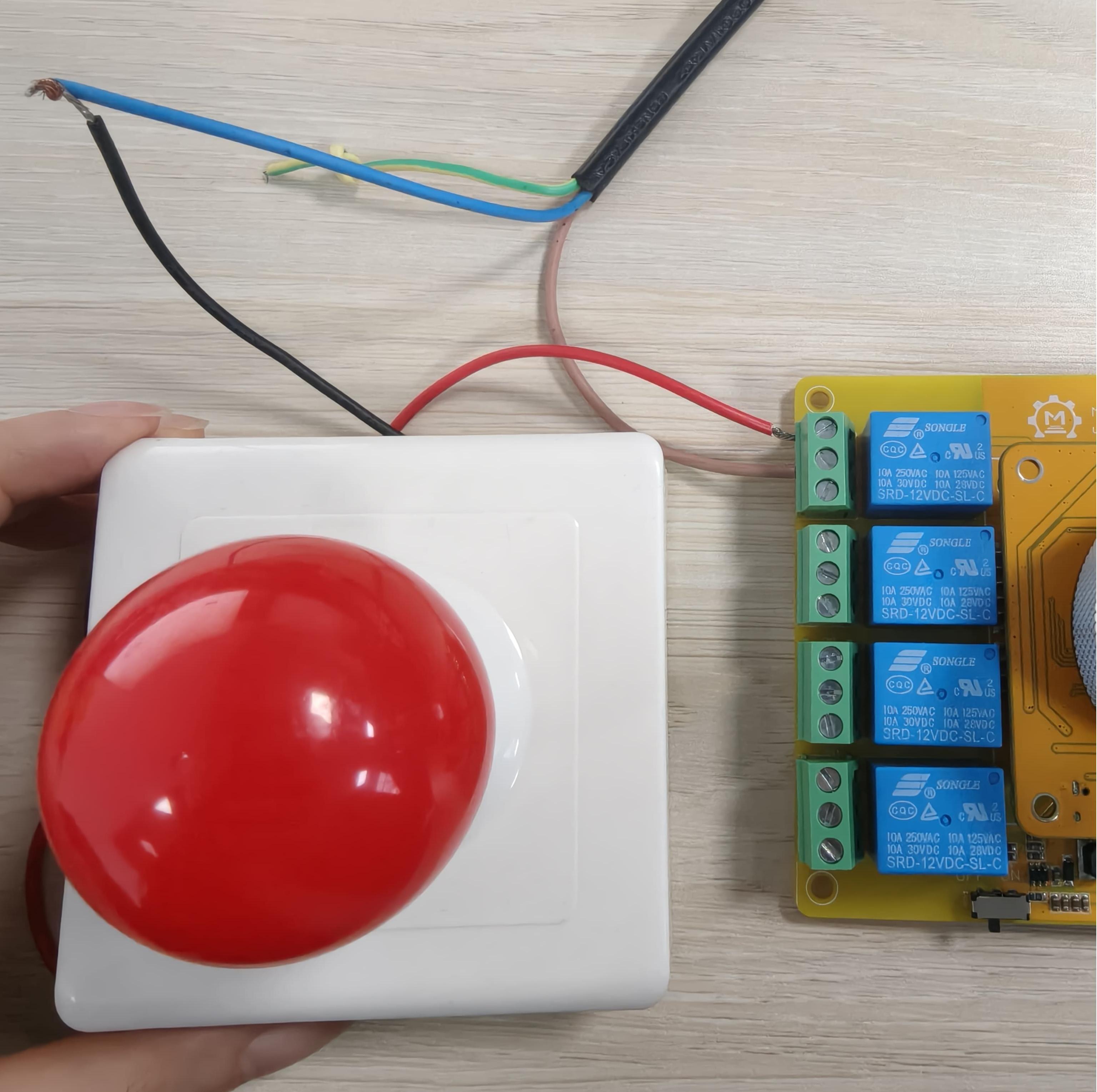
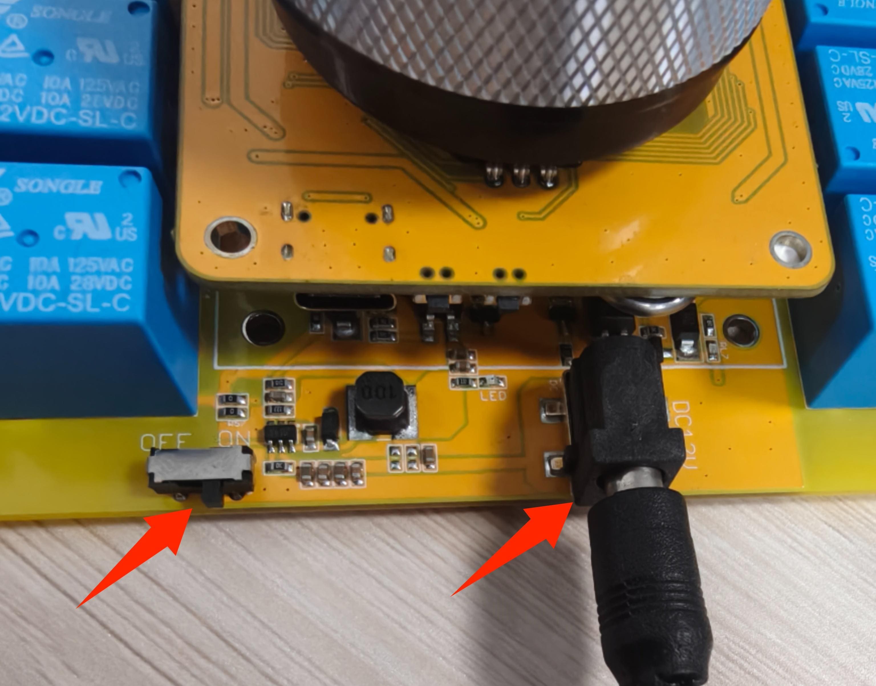
2.Connect to the expansion board using the 12V power adapter, connect the 220v power supply and toggle the switch to the ON label.
Usage:
This 8 Channel Relay has the following functions:
- Set the current time
- Relay switch control
- Timer switch
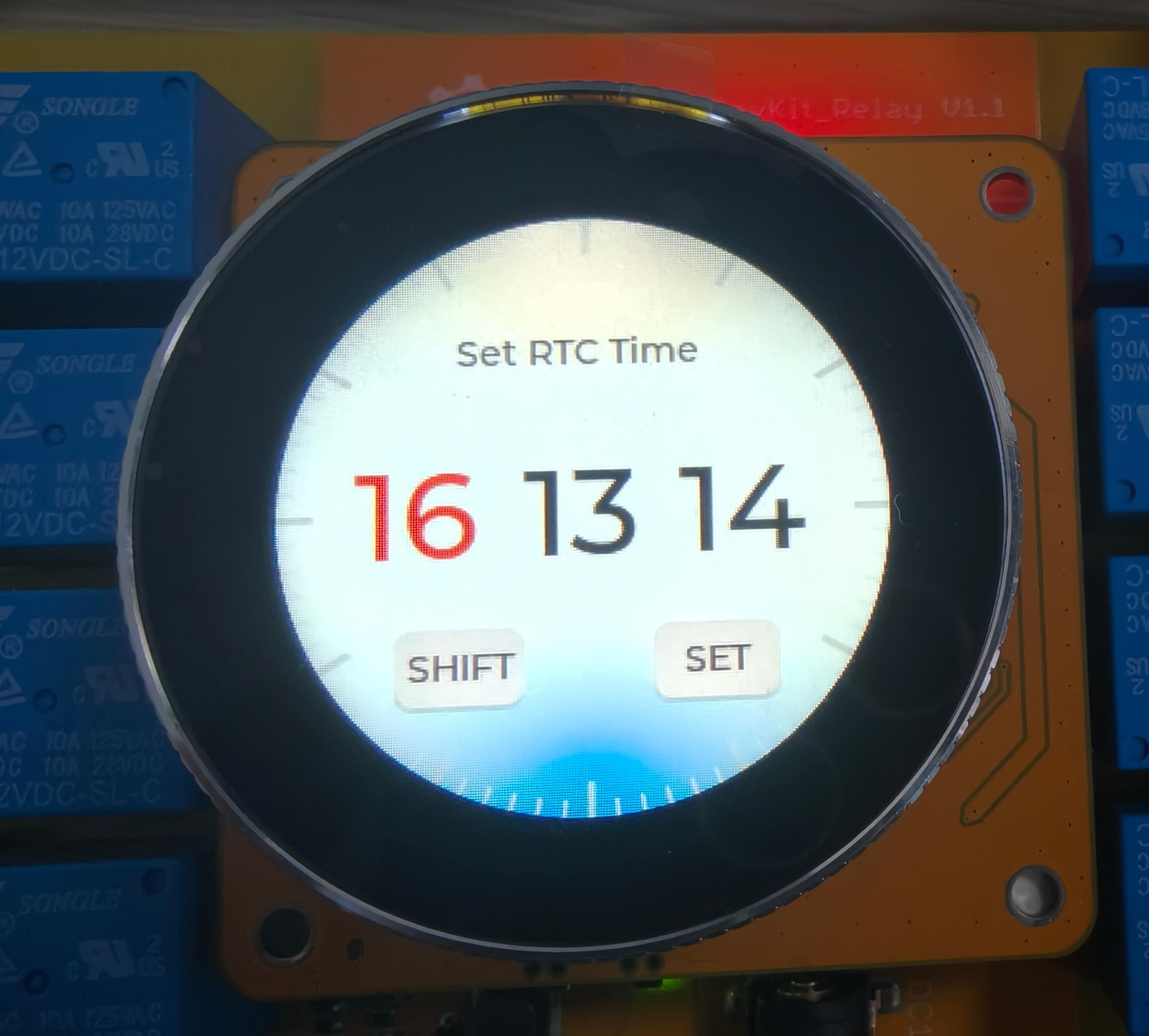
1.Set the current time
- Set the hour, minute and second of the time by knob.
- Click the SHIFT button to toggle the hour, minute and second settings.
- After setting the hours, minutes and seconds, you can click the SET button to switch to the relay control.
2.Relay switch control
- Change the channel of the relay by knob.
- Click on the toggle switch to open the corresponding relay channel.
- Click the Timer Switch button switch to the Timing page.
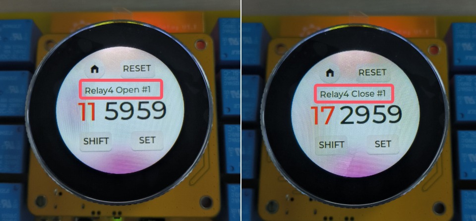
3.Timer switch
Note: The channel on which timing is set depends on the current position of the knob; if the current knob is on channel 4, timing is set for channel 4.
- Set the hour, minute and second of the time by knob.
- Click the SHIFT button to toggle the hour, minute and second settings.
- Click the SET button to confirm the currently set time and the page will change to set the timer for the relay to switch off.
- Click the RESET button to reset the all alarm.
- Click the home button to exit the timer setting and go to the control page of the relay.
2.5 Step Motor Driver
Hardware preparation:
- MaTouch 1.28" Dev_ESP32S3 Controller
- MaTouch 1.28" Dev_Step Motor Driver
- Two Stepper motor
- 12V Power Adapter
1.Connect the stepper motor wires to the expansion board according to the following table. Another stepper motor in the same way.
| Expansion Board | Stepper motor |
|---|---|
| A1+ | Black Wire |
| A1- | Green Wire |
| B1- | Blue Wire |
| B1+ | Red Wire |
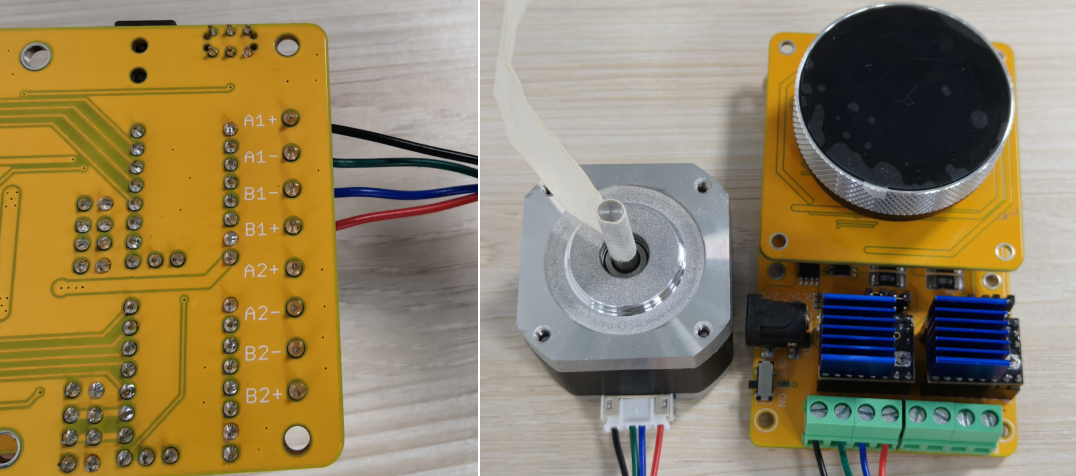
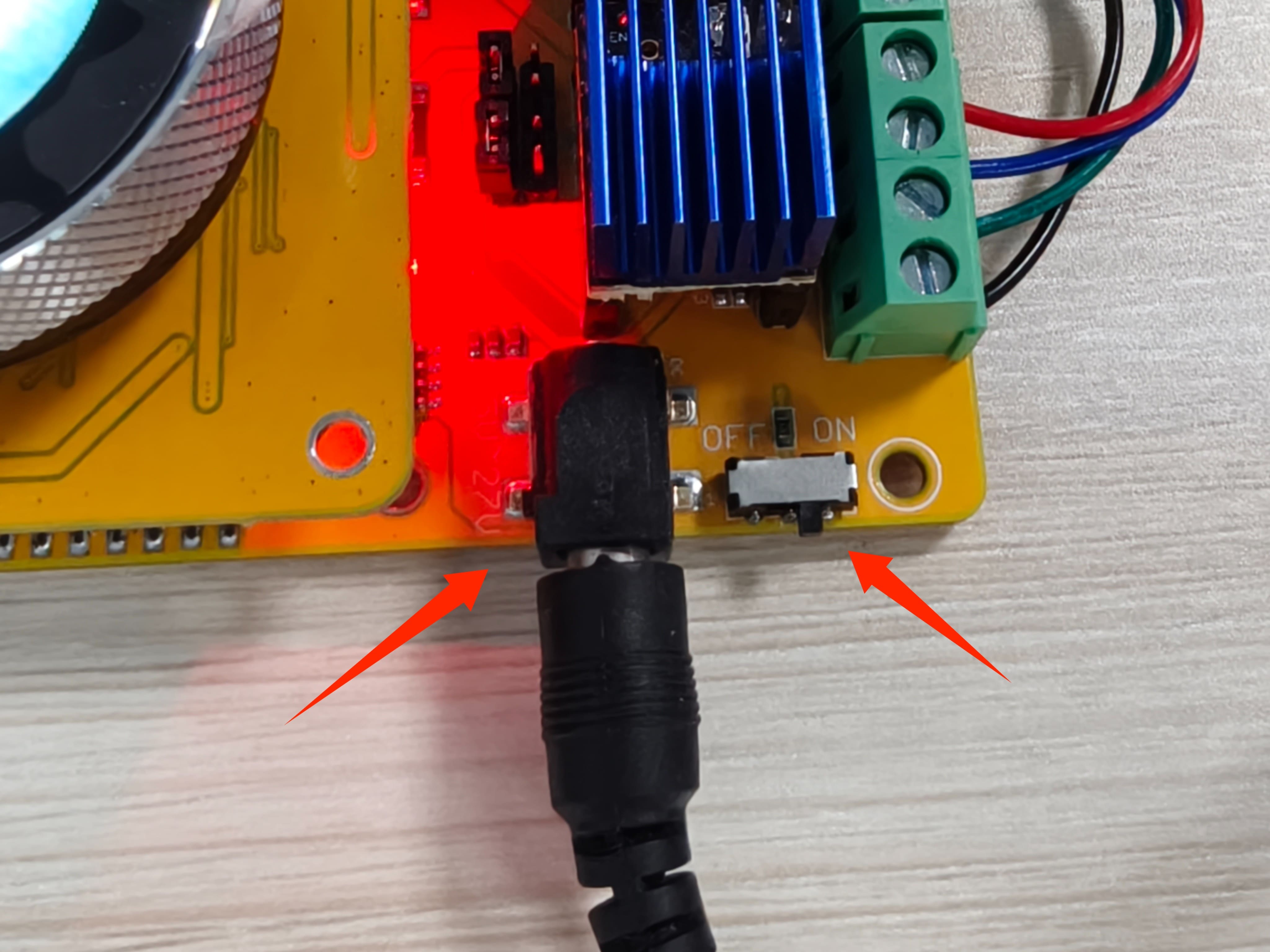
2.Connect to the expansion board using the 12V power adapter and toggle the switch to the ON label.
Usage:
This Step Motor Driver has the following functions:
- Adjust the speed of the stepper motor
- Adjust the stepper motor position
- Adjust the value of the step angle
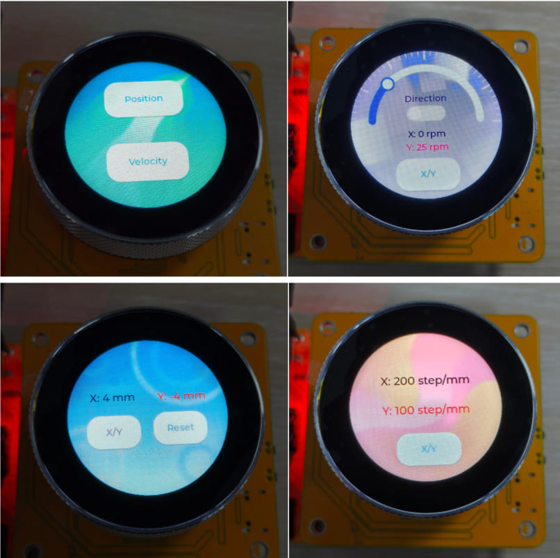
1.Mode Selection
- Click the Position button to enter the position mode.
- Click the Velocity button to enter the speed mode.
Note: After selecting a mode, you can swipe right on the screen to return to the mode selection page.
2.Position mode
-
Click the Position button to enter the position adjustment mode.
-
Change the position of the stepper motor by knob.
- Click on the X/Y button to switch motors.
- Click on the Reset button to clear the motor position to 0.
Note: If you're on the Speed Adjustment page, you can swipe right on the screen to return to the mode selection page.
- Swipe left on the Adjust Position page to go to the Step Angle Adjustment page.
- Change the step angle of the stepper motor by knob.
- Click on the X/Y button to switch motors.
Note: The greater the step angle, the greater the angle of position adjustment.
3.Speed mode
- Click the Velocity button to enter the speed mode.
- Change the speed of the stepper motor by knob.
- Click on the Direction switch to change the direction of the stepper motor.
- Click on the X/Y button to switch motors.
Note: If you're on the Position Adjustment page, you can swipe right on the screen to return to the mode selection page.
About stepper motor subdivision
The default step angle of the 42 stepper motor is 1.8°.
The code sets the default value of the step angle to 200.
int unit_x = 200; //Motor 1
Not subdivided to turn a circle to 360/1.8 ° = 200 steps, corresponding to 1 step 1.8°;
Here to set the value directly to 200, so twist it to turn 200 * 1.8 = 360°
If it is 16 subdivisions, one turn should be (360/1.8)*16=3200 steps, corresponding to 1 step 0.1125°.
Here to set the value directly to 200, so twist a turn on the turn 200 * 0.1125 = 22.5°
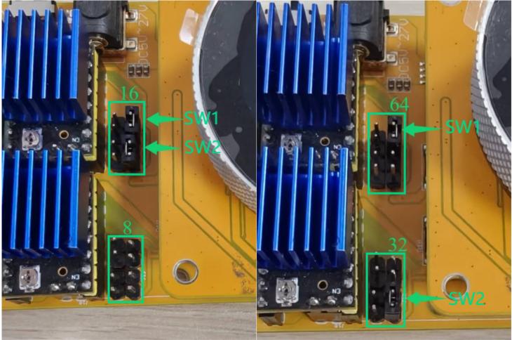
Subdivision can be changed by changing the pcb wiring cap:
| SW1 | SW2 | Function |
|---|---|---|
| connected | connected | 16 subdivision |
| disconnected | disconnected | 8 subdivision |
| connected | disconnected | 64 subdivision |
| disconnected | connected | 32 subdivision |
2.6 DC Driver
Hardware preparation:
- MaTouch 1.28" Dev_ESP32S3 Controller
- MaTouch 1.28" Dev_DC Dimmer
- Two motors
- 12V Power Adapter
1.Connect the motor to the expansion board via the row of wires.
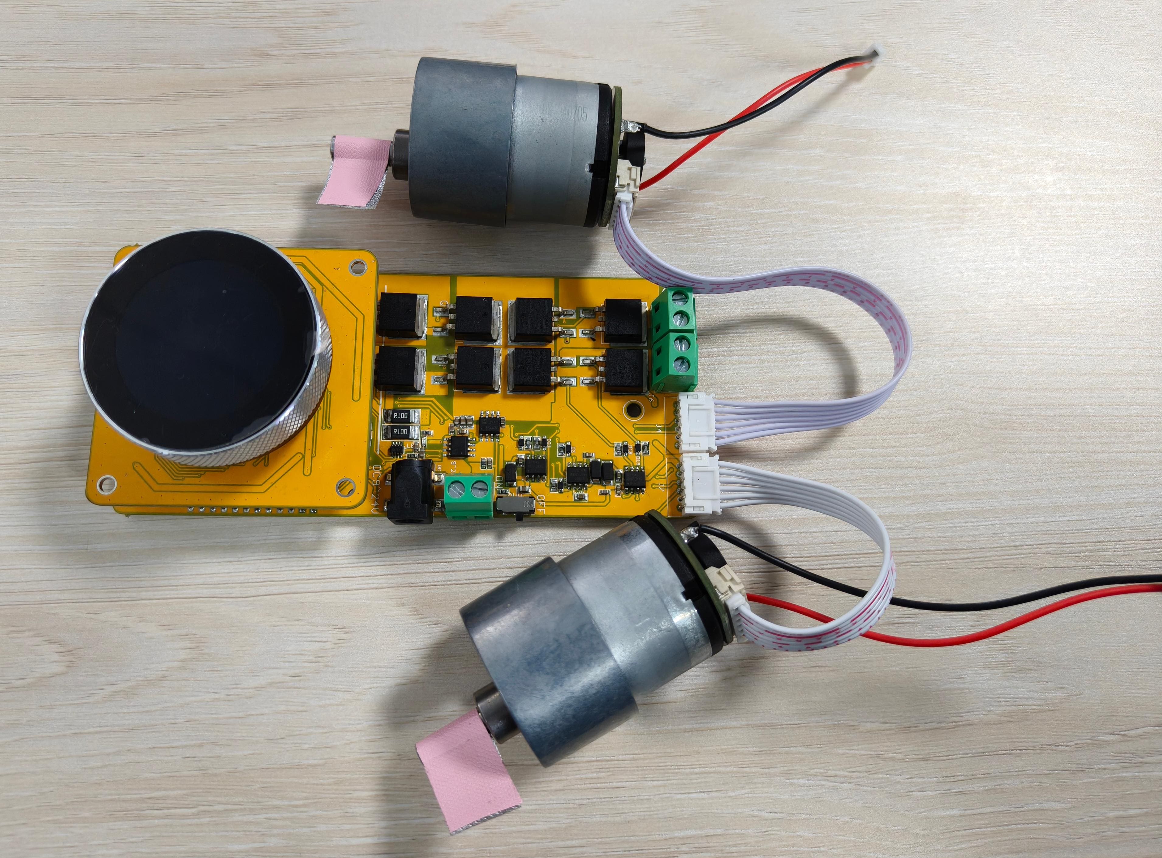
2.Connect to the expansion board using the 12V power adapter and toggle the switch to the ON label.
Usage:
This DC Dimmer has the following functions:
- Adjust the speed of the motor.
- Set the motor forward and reverse
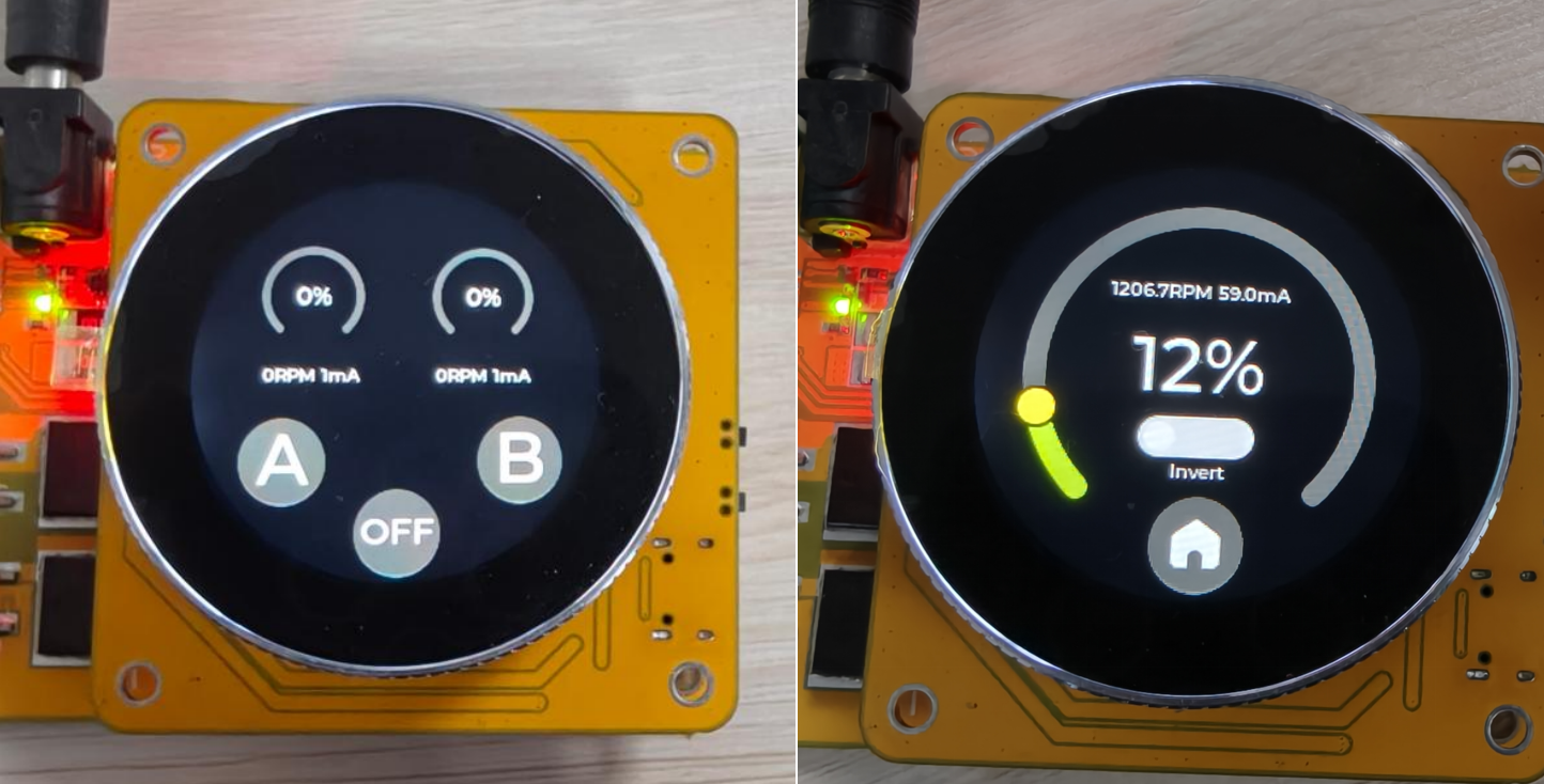
1.Main Panel View
- Click on the A or B button to adjust the corresponding motor speed or forward/reverse rotation.
- Click on OFF button to stop both motors.
2.Adjustment of speed and forward/reverse rotation
- Change the speed of the motor by knob.
- Click on the Invert switch to change the speed of the motor.
- Click on the home button to return to the Main Panel View.
2.7 AC Dimmer
Hardware preparation:
- MaTouch 1.28" Dev_ESP32S3 Controller
- MaTouch 1.28" Dev_AC Dimmer
- A lamp
- 220V power supply
1.Wiring according to the following table
| Expansion Board LO | lamp FireWire |
|---|---|
| Expansion Board NO | lamp ZeroWire |
| Expansion Board LI | 220V power FireWire |
| Expansion Board NI | 220V power ZeroWire |
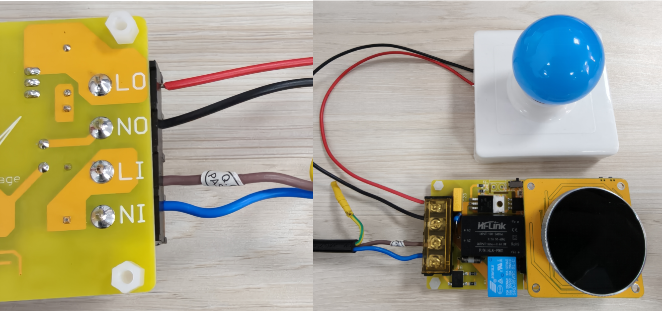
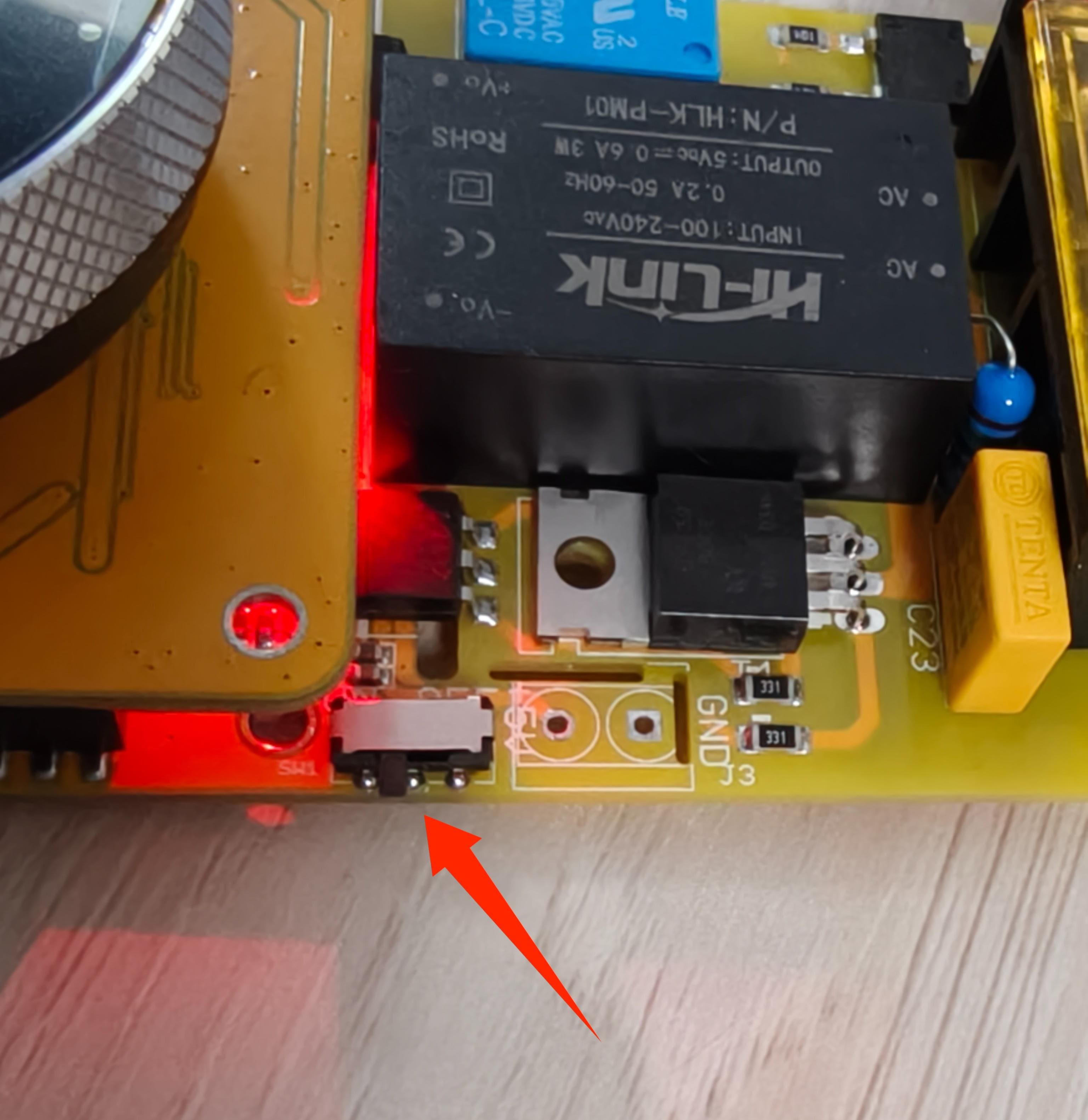
2.Connect the 220v power supply and toggle the switch to the ON label.
Usage:
1.Brightness adjustment
- Change the Brightness of the lamp by knob.
2.Switch Settings
- Click on the Centre Button to control the lamp on/off.
3. How to upload code?
3.1 Development environment
- Install the Arduino IDE V1.8.19/V2.3.4 If you haven’t installed the ESP32 Board SDK yet, follow the steps in this guide to get started quickly.
For the ESP32-S3 Development board version, we recommend using versions that have been verified, such as 3.0.7, which is more stable, and less prone to errors.
Note: Different computers may have different port numbers when connecting to a development board. Please select the correct port number based on the development board you are connecting to.
Please download the relevant driver libraries before using these demos.
Download the library from github.
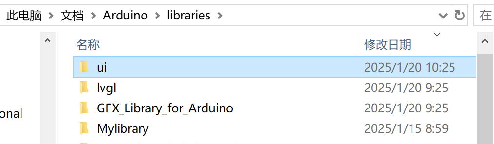
Once the download is complete, copy these libraries into the Arduino library.
- The default is usually in the "C:\Users\Your username\Documents\Arduino\libraries"

Note: All kit work requires the involvement of the ESP32S3 Controller, and all of the following routines are programmed by burning code into the ESP32S3 Controller.
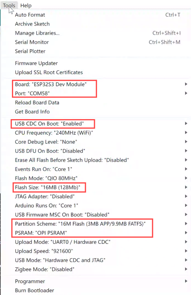
Before uploading the code, please set the parameters of the tools as shown in the picture below.
3.2 RGB Matrix Panel Driver
1.Download the SD card file from github and save it to the SD card.
Note: You can only save in the first directory, you can't create a folder to save in.
2.Download the ui library from github.
Once the download is complete, copy these libraries into the Arduino library.
- The default is usually in the "C:\Users\Your username\Documents\Arduino\libraries"
3.Open the LED_Screen by Arduino IDE.
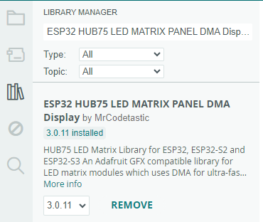
4.Install ESP32 HUB75 LED MATRIX PANEL DMA Display library v3.0.11
5.Install AnimatedGIF library v2.1.1

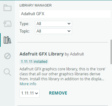
6.Install Adafruit GFX Library v1.11.11
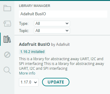
7.Install Adafruit BusIO library v1.16.2
8.Use Type-C USB cable to connect the board and PC.set the parameters of the tools.
9.Click the Upload button in the Arduino IDE and wait for the code to upload.
3.3 RGB LED Strip Driver
1.Download the ui library from github.
Once the download is complete, copy these libraries into the Arduino library.
- The default is usually in the "C:\Users\Your username\Documents\Arduino\libraries"
2.Open the RGB_LED_Strip by Arduino IDE.
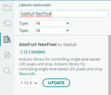
3.Install Adafruit NeoPixel library v1.12.3
4.Use Type-C USB cable to connect the board and PC.set the parameters of the tools.
5.Click the Upload button in the Arduino IDE and wait for the code to upload.
3.4 Relay with 8 channels
1.Download the ui library from github.
Once the download is complete, copy these libraries into the Arduino library.
- The default is usually in the "C:\Users\Your username\Documents\Arduino\libraries"
2.Open the Relay_8_Channel by Arduino IDE.
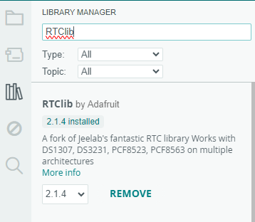
3.Install RTClib v2.1.4
4.Install Adafruit BusIO v1.16.2
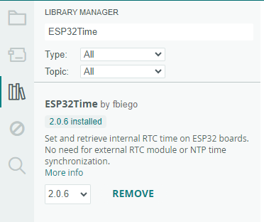
5.Install ESP32Time v2.0.6
6.Use Type-C USB cable to connect the board and PC.set the parameters of the tools.
7.Click the Upload button in the Arduino IDE and wait for the code to upload.
3.5 Step Motor Driver
1.Download the ui library from github.
Once the download is complete, copy these libraries into the Arduino library.
- The default is usually in the "C:\Users\Your username\Documents\Arduino\libraries"
2.Open the Step_Motor by Arduino IDE.
3.Use Type-C USB cable to connect the board and PC.set the parameters of the tools.
4.Click the Upload button in the Arduino IDE and wait for the code to upload.
3.6 DC Driver
1.Download the ui library from github.
Once the download is complete, copy these libraries into the Arduino library.
- The default is usually in the "C:\Users\Your username\Documents\Arduino\libraries"
2.Open the DC_Driver by Arduino IDE.
3.Install Adafruit BusIO v1.16.2
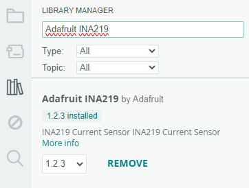
4.Install Adafruit INA219 v1.2.3
5.Use Type-C USB cable to connect the board and PC.set the parameters of the tools.
6.Click the Upload button in the Arduino IDE and wait for the code to upload.
3.7 AC Dimmer
1.Download the ui library from github.
Once the download is complete, copy these libraries into the Arduino library.
- The default is usually in the "C:\Users\Your username\Documents\Arduino\libraries"
2.Open the AC_Dimmer by Arduino IDE.
3.Use Type-C USB cable to connect the board and PC.set the parameters of the tools.
4.Click the Upload button in the Arduino IDE and wait for the code to upload.
4. FAQ
You can list your questions here or contact techsupport@makerfabs.com for technology support. Detailed descriptions of your question will help to solve your question.