Lora_Relay
Introduction
This Lora relay module is preloaded Arduino Pro Mini(3.3v 8M) bootloader and simple demo firmware Lora Relay V1.1, the users could freely change/update the firmware with Arduino IDE, with a common UART tool (Note that if there no DTR in your UART tool, you will need to press the reset button to reset the controller Mega328P manually).
Lora Relay transceivers feature the LoRa long-range modem that provides ultra-long range spread spectrum communication and high interference immunity.
Lora Relay offers bandwidth options ranging from 7.8125kHz to 500 kHz with spreading factors ranging from 6 to 12, there are three choices of the working frequency.
Module:LR20IL
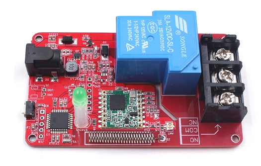
Warning: If Lora Relay is used for controlling AC110V/AC220V Devices, be aware of safety in case of electric shock. This is a relay module that could be controlled by Lora, with a max current 30A/240V. Based on RFM98W, it supports max 4~5 km Lora communication.
| Item | Lora Module | working frequency |
|---|---|---|
| Lora Relay 433M | RFM98W-433MHz/SX1278 | 433MHz |
| Lora Relay 868M | RFM95W-868MHz | 868MHz |
| Lora Relay 915M | RFM95W-915MHz | 915MHz |
Required Materials
- Lora Relay
- Maduino Lora Radio
- USB-to-UART tool
- DC12V Adapter(at least 200mA)
- microUSB Cable
- PC
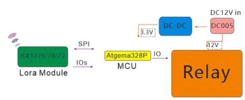
System diagram
This guides help you how to use a Maduino Lora Radio to transmit messages to control the Lora Relay switch on or off. You can get Maduino Lora Radio from:https://www.makerfabs.com/maduino-lora-radio-433m-868m-915m.html
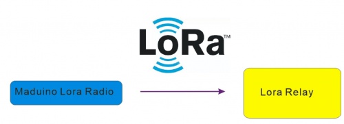
This Lora Relay can be used to switch the AC bulb light on or off.
We integrated the 30A current relay, which will give you a wide use for the large current device.
Notice: Maduino Lora Radio and the Lora Relay must have the same work frequency. Otherwise, it receives nothing from another.
Features
- ATMEL Atmega328P: High Performance, Low Power Atmel®AVR® 8-Bit Microcontroller
- Speed Grade:20Mhz
- Flash:32Kbytes
- RAM: 2KBytes
- EEPROM: 1KBytes
- DC12V input
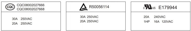
- Max Switch current:30A
- Max Switch Voltage: 250VAC
- Max Switch Power:7200VA
- Relay Contact form: SPDT
- Relay Coil Rated voltage:12V DC
- Relay Coil Rated current:75mA
- Relay Coil Rated resistance:160Ω±10%
- Relay Coil Pick-up Voltage: 75%Max
- Relay Coil Dropout Voltage: 10%Min
- Relay Coil Maximum voltage: 130%Max
- Mechanical Service life: 100,000 operations min. (at 1,800 operations/hour)
- Electrical Service life: 10,000,000(at 1,800 operations/hour)
- Temperature Range: -40C to 85C
| Indicator LED | Status |
|---|---|
| PWR | Light on when powered on, light off when powered off |
| RL | Light on when COM connects to NO, Light off when COM connect to NC Normally light off |
| Status | Blink, can be controlled by PIN D5 |
Usage
Hardware Connections
Pins The following table lists all of the relay's pins and their functionality.
| Pin | Description |
|---|---|
| NC | Normally Closed |
| NO | Normally Opened |
| COM | Switch Common |
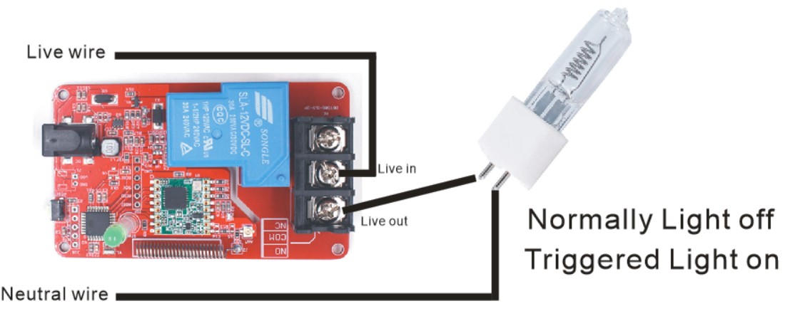
Normally, when Pin D4 output LOW the relay is not triggered, COM connects to NC. Contrarily, when Pin D4 output HIGH the relay is triggered, COM connects to NO. The Power LED will light up when the board is powered. The RL LED will light up when the relay has been triggered. The onboard screw terminal should be used to connect your high-power load. The middle COM pin should be hooked up to the Live wire (Usually black) coming from the wall, while NO or NC should be connected to the Live wire on the device side of things.
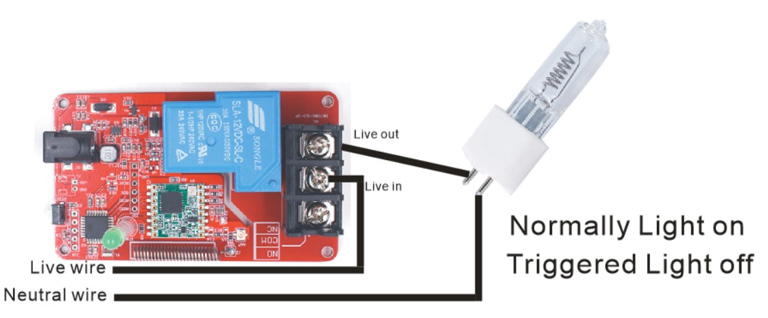
Example wire connection Note: Not sure about what color insulation wiring is used in your region? Check out the standard wire insulation colors listed online for reference. If you are unsure about the standard wiring color in your region, please consult a certified electrician to connect to the AC input voltage side.
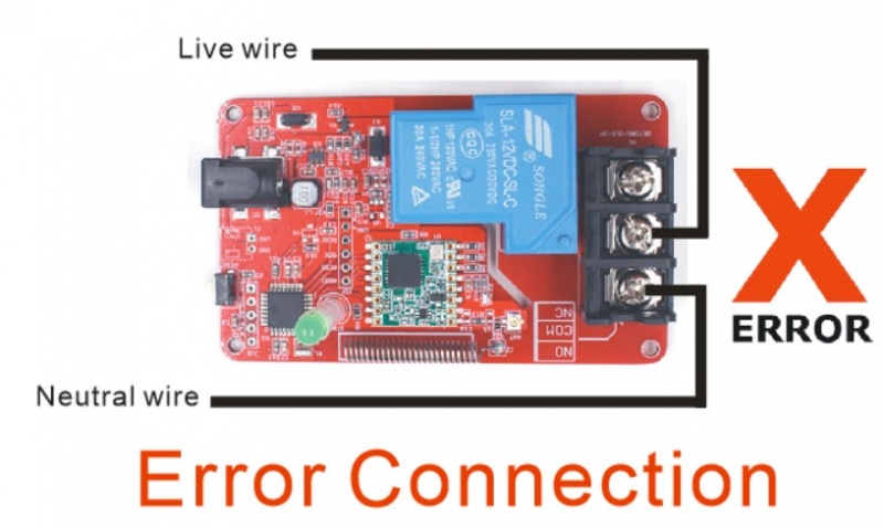
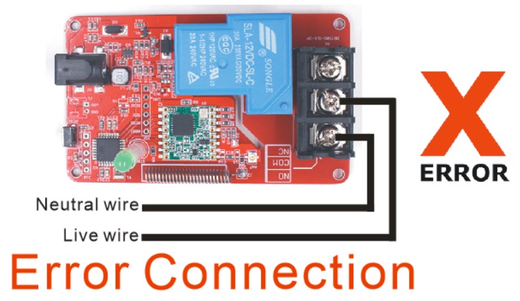
⚡ Warning! Make sure the cable is not plugged into the wall as you cut into the wire in the following section. You'll also need to place the relay in line with the AC powered item you're attempting to control. You'll have to cut your live AC line (usually black or red) and connect one end of the cut wire to COM and the other to NC or NO, depending on what you want the resting state of your device to be. If your AC device is going to be on for most of the time, and you occasionally want to turn it off, you should connect one end to COM and the other to NC. Connect to NO if the device will be off for most of the time. ⚡ Warning! Please be careful when handling the contacts when the cable is plugged into a wall outlet. Touching the contacts while powered could result in injury. Forbidding connect Live and Neutral wire to the onboard screw terminal, it will make Live and Neutral in short circuit(or phase mismatch) in normal case or when relay triggered.
Software setup
The Lora relay needs a Transmitter to Signal to it. How to setting the Transmitter. Take Maduino Lora Radio, for example.
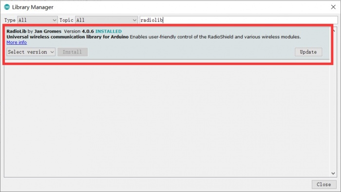
- Install RadioLib library(4.0.6). Click “Tools> Manager Libraries” to search for and install the RadioLib library.
Open LoraTester_LoraRadio_V1.0, Select the test code corresponding to the frequency verify and upload the firmware to Lora Relay.
Choose the frequency macro according to your board is 433Mhz or 868Mhz or 915Mhz. please check the communication frequency in the code.
If your Lora board is 433MHz:
#define FREQUENCY 434.0
If your Lora board is 868MHz:
#define FREQUENCY 868.0
If your Lora board is 915MHz:
#define FREQUENCY 915.0
Plug the Maduino Lora Radio to PC via microUSB cable.
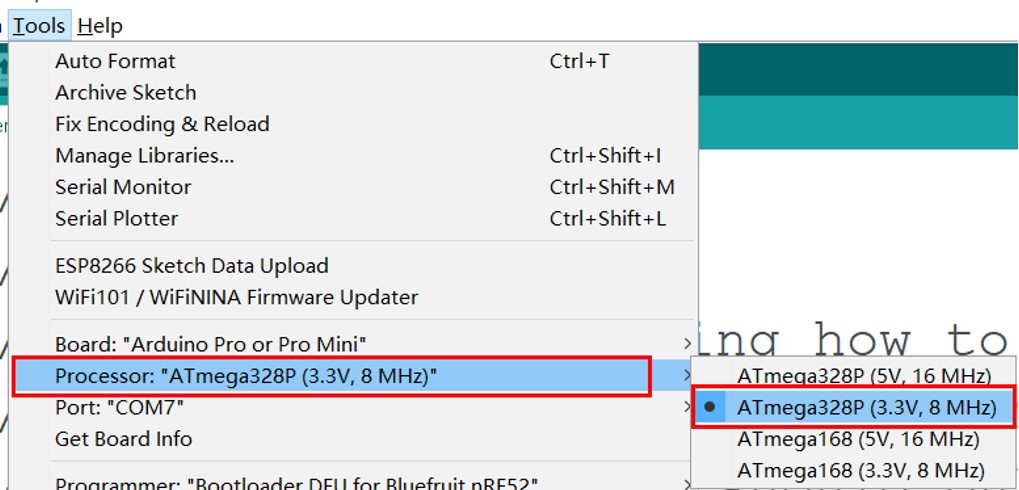
Select the Arduino Pro or Pro mini(3.3V,8MHz)
Verify and upload the code.
Note:The Maduino Lora radio as a Lora transmitter in this demo.
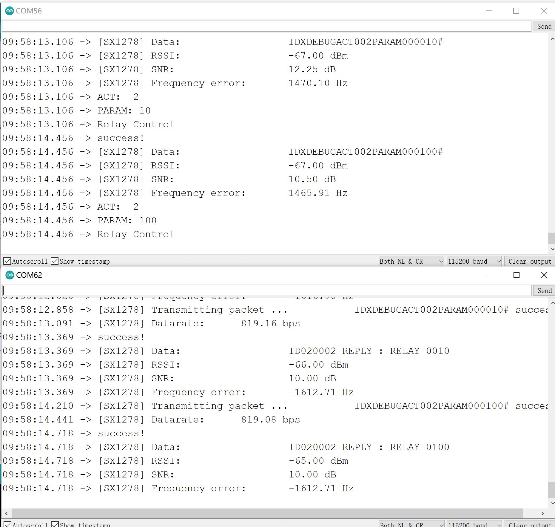
Result
The Transmitter will send messages via Lora 433/868/915Mhz frequency. And the Lora Relay will receive the result and print them in the Serial Monitor. The Lora Relay Received the message from the Maduino Lora Radio, it will switch on or off repeatedly.
The default configurations of Lora Relay:
| Item | value | description |
|---|---|---|
| Lora Frequency | 433MHz/868Mhz/915Mhz | Depend on which frequency you bought |
| Preamble Length | 8 | |
| transmitter power | 23dbm | |
| Bandwidth | 125Khz | |
| Spread Factor | 128chips/symbol | Sf7 = 128chips/symbol |
| Cycle Rate | 4/5 | CodeRate1= 4/5 Cycle Rate |
| CRC | on |
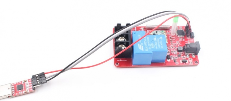
Program upload
Lora Relay requires a USB-to-UART tool to upload firmware to it, you can get it from here.
Install the CP2102 driver from:https://www.silabs.com/products/development-tools/software/usb-to-uart-bridge-vcp-drivers
| Lora Relay | USB-to-UART Tool |
|---|---|
| 3V3 | 3V3 |
| GND | GND |
| RX | TXD |
| TX | RXD |
Open the code [02RELAY.ino]((https://github.com/Makerfabs/Lora-Relay), Users can refer to those routines to write code for Lora relay.
Users can self-programming and burn the program to the Lora relay!
FAQ
You can list your question here or contact techsupport@makerfabs.com for technology support. Detailed descriptions of your question will be helped to solve your question.