PICO Servo Driver
Introdction
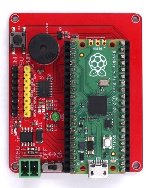
PICO Servo Driver is a platform based on raspberry pi pico, which is designed for driving and controlling servos. The board comes with an 8-bit level translator and 8 channels GPIO headers that can connect the servo directly. Now you can build your new project about servo by trying out the Raspberry PI Pico.
Model:PICO6DOFR
Features
- Standard Raspberry Pi Pico header.
- Onboard 8-bit level translator TXB0108PWR for driving servos.
- 8-channel expansion GPIOs for servos.
- Onboard Active buzzer.
- One button.
- Power supply: 5V.
Interfaces
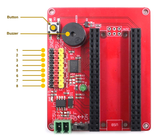
- Servo header
| Index | Black | Red | Yellow |
|---|---|---|---|
| 1 | GND | 5V | GP16 |
| 2 | GND | 5V | GP17 |
| 3 | GND | 5V | GP18 |
| 4 | GND | 5V | G019 |
| 5 | GND | 5V | GP20 |
| 6 | GND | 5V | GP21 |
| 7 | GND | 5V | GP22 |
| 8 | GND | 5V | GP26 |
- Other connection
| GPIO | |
|---|---|
| Button | GP14 |
| Buzzer | GP15 |
Usage
- Basic usage with PIO RP2040
Full code is in : PICO_Merchanical_Hand_Driver/Arm6axis/
Most of MCU have some kind of PWM output, for example the analogWrite() in Arduino, it outputs PWM to related pins, with UNO, these pins can be 3/5/6/9/10 and 11, to control the connected LED brightness or motor speed.
But if these hardware pins are already used by some other functions, such as the D11 in UNO(MOSI in SPI communication), most users simulate the PWM in firmware, which needs hardware times/interrupts, which takes big burden to the MCU. and seriously, when the PWM frequency gets high, or multiple PWM are needed, the frequency get unstable, as the MCU maybe too busy to deal with them all, on time.
And more, for servo control, it may need a signal with 20ms frequency, with 0.1%~99.9% logic high duty, hardware PWM can not output such a signal, while with firmware simulating, it will take a lot of timer/interrupt and MCU ability, especially when it comes to multiple servos simultaneously. Here we introduce a simple way, based on the hardware PIO in RP2040(Raspberry Pi PICO), to control multiple servos without the MCU engaging in much.
PIO
The programmable input/output block (PIO) is a versatile hardware interface. It can support a variety of IO standards, including:
- 8080 and 6800 parallel bus
- I2C
- 3-pin I2S
- SDIO
- SPI, DSPI, QSPI
- UART
- DPI or VGA (via resistor DAC)
There are 2 identical PIO blocks in RP2040. Each PIO block has dedicated connections to the bus fabric, GPIO and interrupt controller.
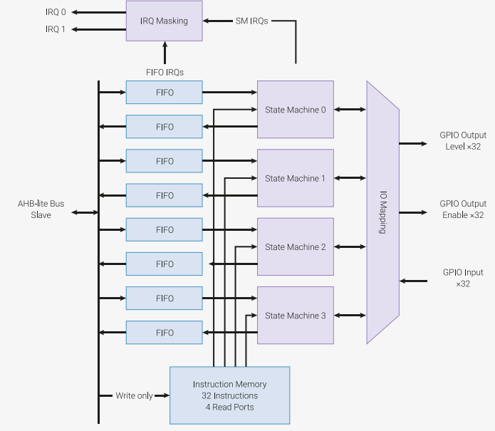
PIO is programmable in the same sense as a processor. There are two PIO blocks with four state machines each, that can independently execute sequential programs to manipulate GPIOs and transfer data. Unlike a general purpose processor, PIO state machines are highly specialized for IO, with a focus on determinism, precise timing, and close integration with fixed-function hardware. Each state machine is equipped with:
- Two 32-bit shift registers – either direction, any shift count
- Two 32-bit scratch registers
- 4×32-bit bus FIFO in each direction (TX/RX), reconfigurable as 8×32 in a single direction
- Fractional clock divider (16 integers, 8 fractional bits)
- Flexible GPIO mapping
- DMA interface, sustained throughput up to 1 word per clock from system DMA
- IRQ flag set/clear/status
Outputs PWM with PIO
Open Thonny, Create a new Python file, input the following code and execute:
from rp2 import PIO, StateMachine, asm_pio
from machine import Pin
import time


@asm_pio(set_init=PIO.OUT_LOW)
def pwm_1():
    set(pins, 1)
    set(pins, 0)


def test():
    sm1 = StateMachine(1, pwm_1, freq=1000000, set_base=Pin(0))
    sm1.active(1)
    while 1:
        print("Run....")
        time.sleep(5)


test()
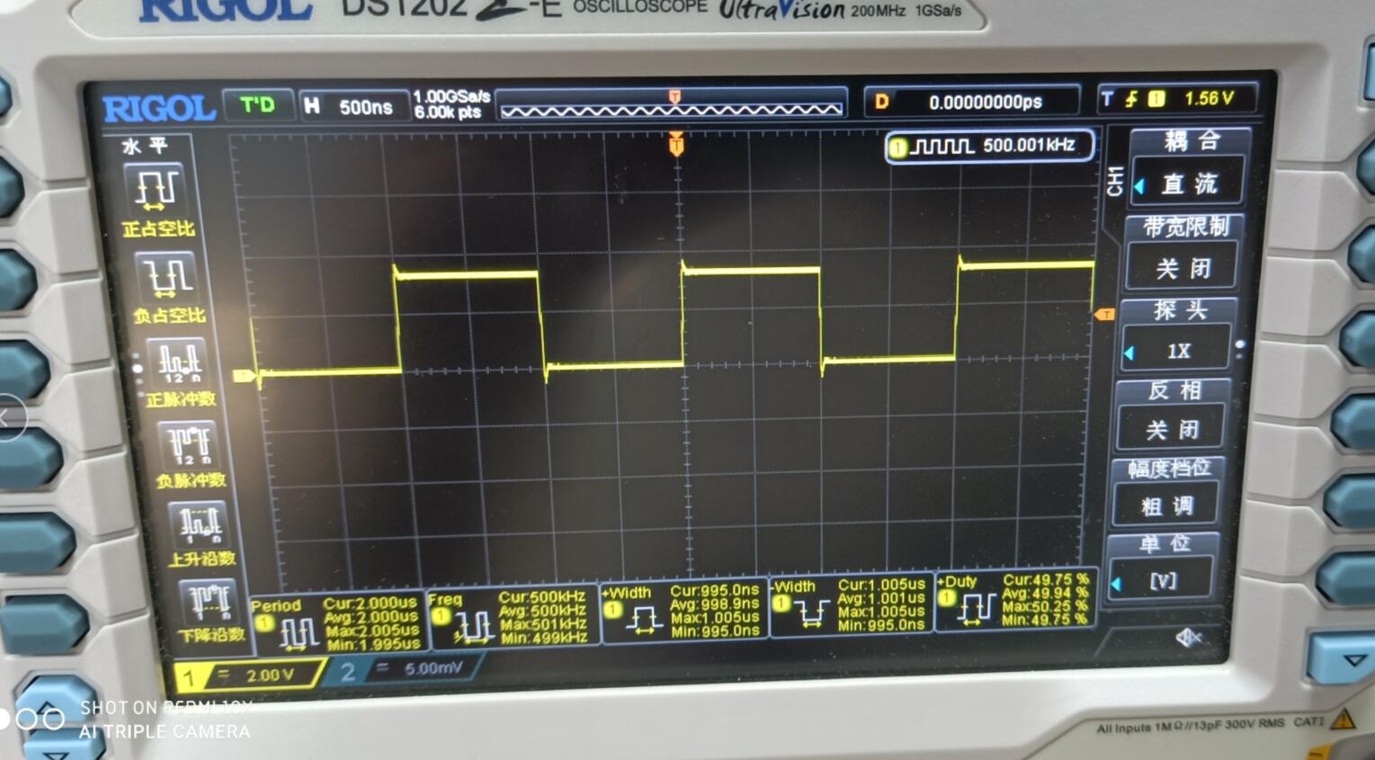
Test the GPIO0 with Oscilloscope:
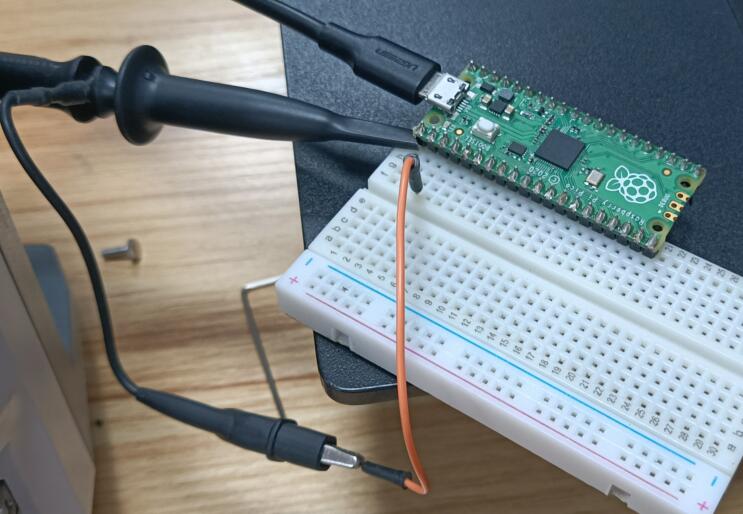
PWM with frequency 500K Hz:
- Assembly Parts
@asm_pio(set_init=PIO.OUT_LOW)
def pwm_1():
    set(pins, 1)
    set(pins, 0)
@asm_pio defines this function a PIO assembly function
set(pins, 1) is not a python function, but a PIO assembly function(we will explain it some later,together with other PIO assembly functions), it sets the logistic 1 and 0. each PIO assembly function take 1 PIO cycle, so there 2 assembly functions here , wit 2 PIO cycles.
PIO to Drive Servo
How do drive a servo
The Servo angle is controlled by the duty of input signal, called PCM. Basiclly, it is a cycle with 20ms duration, with logic HIGH 0.5ms~2.5ms, and the logic HIGH finally controls the how the angles. for example, 1.5ms means middle position 90° on the servo(for 180° servo, 90° is the middle position), and if the logic HIHG width smaller than 1.5ms, the servo turns towards to 0°, and vice versa.
Servo control Main
from machine import Pin
import time

T_X = 4000
T_Y0 = 3900
T_Y180 = 3500


#freq=800000 0.5ms y=3900 2.5ms y=3500 unit_y:2.5us == 0.45degree
@asm_pio(set_init=PIO.OUT_LOW)
def servo_ctrl2():

    mov(x, isr)
    set(pins, 1)

    label("for")
    jmp(not_x,"over")
    jmp(x_not_y,"dec")
    set(pins, 0)
    label("dec")
    jmp(x_dec,"continue")
    label("continue")
    jmp("for")

    label("over")
    nop()[3]


class PIO_SERVO:
    def __init__(self, sm_id, pin):
        self._sm = StateMachine(
            sm_id, servo_ctrl2, freq=800000, set_base=Pin(pin))
        # Use exec() to load max count into ISR
        #self._sm.put(T_Y0)
        self._sm.put(T_X)
        self._sm.exec("pull()")
        self._sm.exec("mov(y, osr)")
        self._sm.put(T_X)
        self._sm.exec("pull()")
        self._sm.exec("mov(isr, osr)")
        self._sm.active(1)

    def set(self, pio_cycle):
        self._sm.active(0)
        self._sm.put(pio_cycle)
        self._sm.exec("pull()")
        self._sm.exec("mov(y, osr)")
        self._sm.put(T_X)
        self._sm.exec("pull()")
        self._sm.exec("mov(isr, osr)")
        self._sm.active(1)

    def set_ms(self, ms):
        if ms < 0.5:
            ms = 0.5
        elif ms > 2.5:
            ms = 2.5

        pio_cycle = int(3900 - (ms - 0.5) * 200)
        self.set(pio_cycle)

    def set_angle(self, angle):
        ms = (angle + 90.0) / 90.0 + 0.5
        self.set_ms(ms)


def test():

    servo = PIO_SERVO(0, 16)
    # servo.set(180)
    # servo.set_ms(1.5)
    while 0:
        time.sleep(3)
    while 1:

        # servo.set(T_Y180)
        servo.set_ms(0.5)

        time.sleep(3)

        # servo.set(T_Y0)
        servo.set_ms(2.5)

        time.sleep(3)


#test()
PIO assembly parts
#freq=800000 0.5ms y=3900 2.5ms y=3500 unit_y:2.5us == 0.45degree
@asm_pio(set_init=PIO.OUT_LOW)
def servo_ctrl2():

    mov(x, isr)
    set(pins, 1)

    label("for")
    jmp(not_x,"over")
    jmp(x_not_y,"dec")
    set(pins, 0)
    label("dec")
    jmp(x_dec,"continue")
    label("continue")
    jmp("for")

    label("over")
    nop()[3]
The logic:
- MOVE data in ISR to x;
- set the GPIO to HIGH
- loop
- Check if X is equal to Y, if yes, set GPIO to LOW
- X--
- nops to make it 20 ms duration
PIO MicroPython
T_X = 4000
T_Y0 = 3900
T_Y180 = 3500

class PIO_SERVO:
    def __init__(self, sm_id, pin):
        self._sm = StateMachine(
            sm_id, servo_ctrl2, freq=800000, set_base=Pin(pin))
        # Use exec() to load max count into ISR
        #self._sm.put(T_Y0)
        self._sm.put(T_X)
        self._sm.exec("pull()")
        self._sm.exec("mov(y, osr)")
        self._sm.put(T_X)
        self._sm.exec("pull()")
        self._sm.exec("mov(isr, osr)")
        self._sm.active(1)

    def set(self, pio_cycle):
        self._sm.active(0)
        self._sm.put(pio_cycle)
        self._sm.exec("pull()")
        self._sm.exec("mov(y, osr)")
        self._sm.put(T_X)
        self._sm.exec("pull()")
        self._sm.exec("mov(isr, osr)")
        self._sm.active(1)
Set the state machine frequency 800KHz,1.25us for each command.
Input data to cache and then pull to OSR, and move to registers.
Multiple Servo Control
There 8 state machines, 0~7, in RP2040, to contrl max 8 servo simultaneously with RP2040 PIO.
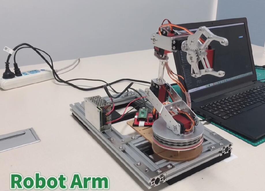
The following code is a six-axis robot arm controlling based on PIO. Divided into steering gear layer, mechanical arm single shaft, mechanical arm, mechanical arm control four layers. A total of six servos are used, and six state machines of the PIO are used for synchronous control.
- PIO Servo
This part contains a PIO-based servo driver, declares a PIO_SERVO Class, and provides methods based on timing and angle control.
#arm6\pio_servo.py

from rp2 import PIO, StateMachine, asm_pio
from machine import Pin
import time

T_X = 4000
T_Y0 = 3900
T_Y180 = 3500


#freq=800000 0.5ms y=3900 2.5ms y=3500 unit_y:2.5us == 0.45degree
@asm_pio(set_init=PIO.OUT_LOW)
def servo_ctrl2():

    mov(x, isr)
    set(pins, 1)

    label("for")
    jmp(not_x,"over")
    jmp(x_not_y,"dec")
    set(pins, 0)
    label("dec")
    jmp(x_dec,"continue")
    label("continue")
    jmp("for")

    label("over")
    nop()[3]


class PIO_SERVO:
    def __init__(self, sm_id, pin):
        self._sm = StateMachine(
            sm_id, servo_ctrl2, freq=800000, set_base=Pin(pin))
        # Use exec() to load max count into ISR
        #self._sm.put(T_Y0)
        self._sm.put(T_X)
        self._sm.exec("pull()")
        self._sm.exec("mov(y, osr)")
        self._sm.put(T_X)
        self._sm.exec("pull()")
        self._sm.exec("mov(isr, osr)")
        self._sm.active(1)

    def set(self, pio_cycle):
        self._sm.active(0)
        self._sm.put(pio_cycle)
        self._sm.exec("pull()")
        self._sm.exec("mov(y, osr)")
        self._sm.put(T_X)
        self._sm.exec("pull()")
        self._sm.exec("mov(isr, osr)")
        self._sm.active(1)

    def set_ms(self, ms):
        if ms < 0.5:
            ms = 0.5
        elif ms > 2.5:
            ms = 2.5

        pio_cycle = int(3900 - (ms - 0.5) * 200)
        self.set(pio_cycle)

    def set_angle(self, angle):
        ms = (angle + 90.0) / 90.0 + 0.5
        self.set_ms(ms)
Mechanical Arm
Declares Arm_axis Class for a robot arm, each axis containing a PIO_SERVO. The six Arm_axis are packaged as a Arm_6 Class, which provides a series of control methods such as initialization, refresh and so on.
#arm6\arm_6axis.py

from pio_servo import PIO_SERVO
import time

# PIN_LIST = [0, 1, 2, 3, 4, 5]
# DIR_LIST = [0, 0, 0, 1, 0, 0]


class Arm_axis:
    def __init__(self, index, pin, direct):
        self.id = index
        self.pin = pin
        self.dir = direct
        # default position is middle
        self.angle = 0.0
        self.servo = PIO_SERVO(self.id, self.pin)

    def set_angle(self, angle):
        if angle < -90.0:
            angle = -90.0
        elif angle > 90.0:
            angle = 90.0
        self.angle = angle

    def fresh(self):
        real_angle = self.angle
        if self.dir == 1:
            real_angle = -real_angle
        self.servo.set_angle(real_angle)

    def angle_report(self):
        return self.angle


class Arm_6:
    def __init__(self, pin_list, dir_list):
        self.axises = []
        for i in range(6):
            self.axises.append(
                Arm_axis(i, pin_list[i], dir_list[i]))

    def flesh_single(self, index):
        self.axises[index].fresh()

    def flesh(self):
        for i in range(6):
            self.axises[i].fresh()

    def set_single_angle(self, index, angle):
        self.axises[index].set_angle(angle)

    def pos_report(self):
        pos = []
        for i in range(6):
            pos.append(self.axises[i].angle_report())

        return pos
Robot Arm Codes Explanation
Provides a set of control commands, including absolute angle and relative angle two kinds of movement, as well as button, buzzer, delay and other commands. The commands can be read in batches from the file in a way similar to GCODE.
#arm6\arm_controller.py

from arm_6axis import Arm_6
import time

RUNFILE = "arm_code2.txt"
DEBUG = 0

PIN_LIST    = [16, 17, 18, 19, 20, 21]
DIR_LIST    = [0, 1, 1, 0, 0, 1]
ANGLE_LIST  = [-2, -40, 75, 75, 0, -10]


DELAY_TIME = 0.5


class Arm_controller:
    def __init__(self, PIN_LIST, DIR_LIST):
        self.arm = Arm_6(PIN_LIST, DIR_LIST)

    def explain_line(self, TEXT):
        if TEXT[0] == "#":
            if DEBUG:
                print(TEXT)
            return 0

        elif TEXT.find("ABS") == 0:
            command_list = TEXT[4:].split(" ")
            if DEBUG:
                print("ABS")
                print(command_list)
            self.explain_absolate(command_list)
            return 1

        elif TEXT.find("REL") == 0:
            command_list = TEXT[4:].split(" ")
            if DEBUG:
                print("REL")
                print(command_list)
            self.explain_relative(command_list)
            return 1

        elif TEXT.find("END") == 0:
            print("COMMAND END")
            print("Finally POS:")
            print(self.arm.pos_report())
            return 2

        elif TEXT.find("POS") == 0:
            self.arm.flesh()
            time.sleep(2)
            print("REALLY POS:")
            print(self.arm.pos_report())
            return 1

        elif TEXT.find("WAIT") == 0:
            time.sleep(2)
            return 1

        elif TEXT.find("SLEEP") == 0:
            sleep_time = int(TEXT[6:])
            print("Sleep " + str(sleep_time) + "...")
            time.sleep(sleep_time)
            return 1

        elif TEXT.find("BUZZ") == 0:
            alarm()
            return 1

        elif TEXT.find("BUTT") == 0:
            input_button()
            return 1

        else:
            print("WARNING : NOT KNOWN COMMAND")
            print(TEXT)
            return -1

    def explain_absolate(self, COMMAND_LIST):
        for part in COMMAND_LIST:
            index = self.get_index(part[0])
            angle = int(part[1:])

            # print(index)
            # print(angle)

            self.arm.set_single_angle(index, angle)
        self.arm.flesh()
        time.sleep(DELAY_TIME)

    def explain_relative(self, COMMAND_LIST):
        pos_list = self.arm.pos_report()
        for part in COMMAND_LIST:
            index = self.get_index(part[0])
            angle = int(part[1:]) + pos_list[index]

            # print(index)
            # print(angle)

            self.arm.set_single_angle(index, angle)
        self.arm.flesh()
        time.sleep(DELAY_TIME)

    # init by angle list
    def init_arm_angle(self, ANGLE_LIST):
        for index in range(6):
            self.arm.set_single_angle(index, ANGLE_LIST[index])
        self.arm.flesh()
        time.sleep(2)

    def get_index(self, part):
        axis_dic = {'A': 0, 'B': 1, 'C': 2, 'D': 3, 'E': 4, 'F': 5}
        return axis_dic[part]


def control_by_file():

    ct = Arm_controller(PIN_LIST, DIR_LIST)
    ct.init_arm_angle(ANGLE_LIST)

    file = open(RUNFILE, "r")

    for line in file:
        print(line)
        if line.isspace():
            continue
        if ct.explain_line(line) == 2:
            break
    file.close()


def control_by_serial():
    ct = Arm_controller(PIN_LIST, DIR_LIST)
    ct.init_arm_angle(ANGLE_LIST)
    line = ""
    while 1:
        line = input()
        if line.isspace():
            continue
        if ct.explain_line(line) == 2:
            break
        line = ""


def control_by_serial_save():
    file = open("Log.txt", "w")
    file.write("#" + str(PIN_LIST) + "\n")
    file.write("#" + str(DIR_LIST) + "\n")
    file.write("#" + str(ANGLE_LIST) + "\n")

    ct = Arm_controller(PIN_LIST, DIR_LIST)
    ct.init_arm_angle(ANGLE_LIST)
    line = ""
    while 1:
        line = input()
        file.write(str(line) + "\n")
        if line.isspace():
            continue
        if ct.explain_line(line) == 2:
            break
        line = ""

    file.close()

def alarm():
    buzzer = machine.Pin(15, machine.Pin.OUT)
    for i in range(500):
        buzzer.value(1)
        time.sleep(0.001)
        buzzer.value(0)
        time.sleep(0.001)

def input_button():
    button = machine.Pin(14, machine.Pin.IN, machine.Pin.PULL_UP)
    print("Wait button press")
    while 1:
        if button.value() == 0:
            time.sleep(0.5)
            if button.value() == 0:
                alarm()
                break
        time.sleep(0.5)
def test():

    while 1:
        control_by_file()
        break
    # control_by_serial()
    # control_by_serial_save()

test()
A simple application-Hanoi control
The following codes is Hanoi control, the youtube video following.
- ABS: absolute angle
- REL: Relative angle
- WAIT
- #remark
- POS: return the absolute angle
- BUTT :wait for button
- BUZZ :buzzer work
- SLEEP set the sleep time
#[16, 17, 18, 19, 20, 21]
#[0, 1, 1, 0, 0, 1]
#[-2, -25, 75, 75, 0, -10]

#claw F-10release,F35grap
#C75 D62, B = 3:5 2:9 1:14
#    3       3       3
#    2       2       2
#    1       1       1
#   [1]     [2]     [3]

#sequence
#1:3 -> 3:1
#1:2 -> 2:1
#3:1 -> 2:2
#1:1 -> 3:1
#2:2 -> 1:1
#2:1 -> 3:2
#1:1 -> 3:3

###############################1:3 -> 3:1
#Locate 1:3
ABS A18 B-20 C75 D62 F-10
WAIT

#drop
ABS B5
WAIT

#Grab
ABS F30

# POS
# [18, 5, 75, 62, 0, 30]

#lift
REL B-6
WAIT

#move to A-18
ABS A-18
WAIT

#move to 3:1
REL B3
REL B3
REL B3
REL B3
REL B3

#release
ABS F-10

# POS
# [-18, 14, 75, 62, 0, -10]

#return
ABS B0
FAQ
You can list your question here or contact techsupport@makerfabs.com for technology support. Detailed descriptions of your question will be helped to solve your question.