ESP32S3 4G LTE CAT1 SIM7670G
1. Introduction
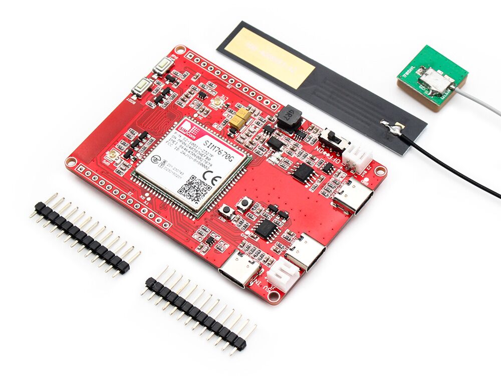
This ESP32S3 4G LTE module utilizes the SIM7670G CAT1 module to assist makers in establishing seamless WiFi/Bluetooth/4G connections. There are 3 versions of Makerfabs 4G LTE products, But the biggest advantage of our new ESP32S3 4G LTE(SIM7670G) module is that it can be used worldwide. ESP32S3 4G LTE(SIM7670G) module offers additional features:
-
Lower Price: This module is based on the SIM7670G 4G module, CAT1, which offers a more affordable price point. The CAT1 is well-suited for IoT applications such as remote sensor monitoring.
-
With ESP32S3 controller, it features WiFi/Bluetooth, which can be used for local application setting (with phone), making it ideal for applications such as shared bike.
Model: ESPSIM7670G
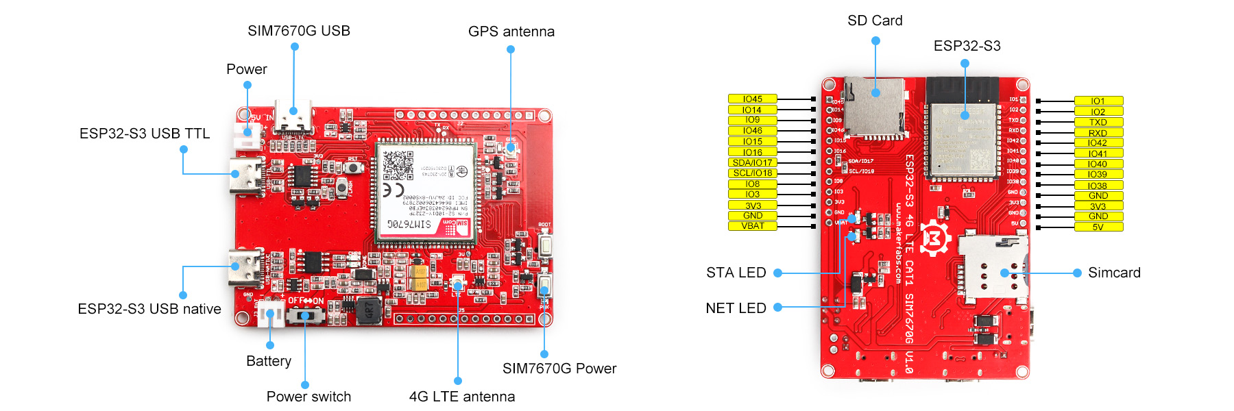
2. Interface
3. Features
- LTE Cat-1, with uplink rate 5 Mbps and downlink rate 10 Mbps
- GNSS Positioning
- Controller: ESP32-S3-WROOM-1, PCB Antenna, 16MB Flash, 8MB PSRAM, ESP32-S3-WROOM-1-N16R8
- 3 USB type-C:ESP32S3 USB Native;ESP32S3 USB TTL;SIM7670G USB
- Supports , SMS, TCP, UDP, DTMF, HTTP, FTP, and so on
- USB supply voltage range: 4.8~5.5V, 5.0V Typically; Battery supply voltage range: 3.4~4.2V, 3.7V Typically
- Onboard charger, up to 1A charge current; Overcharge protection(OCP), 4.3V; Over-discharge protection(ODP), 2.5V
4. Hardware
- Plug the SIM card into the board.
- Plug the GPS antenna into the GPS interface.
- Plug the 4G-GSM antennas into the LTE interface.
- Plug the SD card into the SD card slot.
5. Arduino IDE
- Install the Arduino IDE V1.8.10/V1.8.19 If you haven’t installed the ESP32 Board SDK yet, follow the steps in this guide to get started quickly.
For the ESP32-S3 Development board version, we recommend using versions that have been verified, such as 2.0.8, which is more stable, and less prone to errors.
Note: Different computers may have different port numbers when connecting to a development board. Please select the correct port number based on the development board you are connecting to.
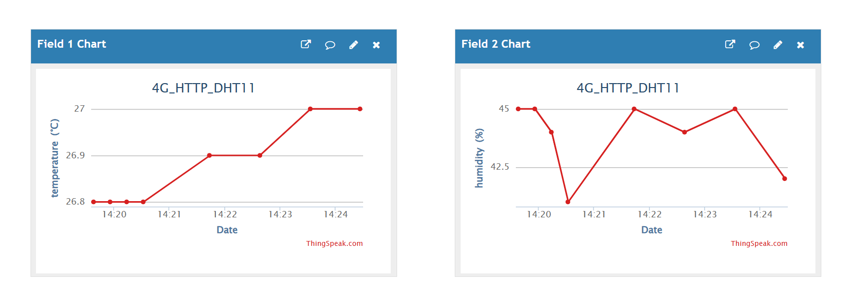
6. Transmit the detection data to Thingspeak
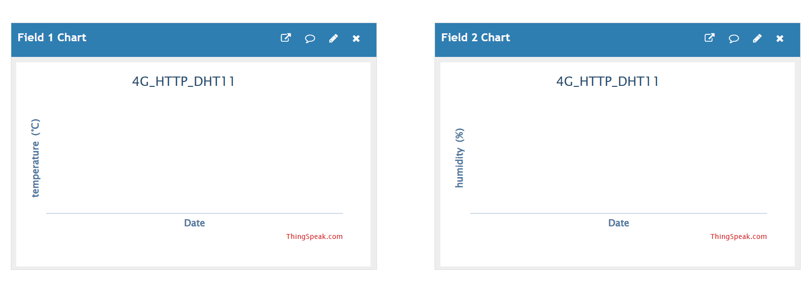
This demo will show you use this device to transmit the temperature and humidity to Thingspeak that the T&H CAN be checked everywhere.
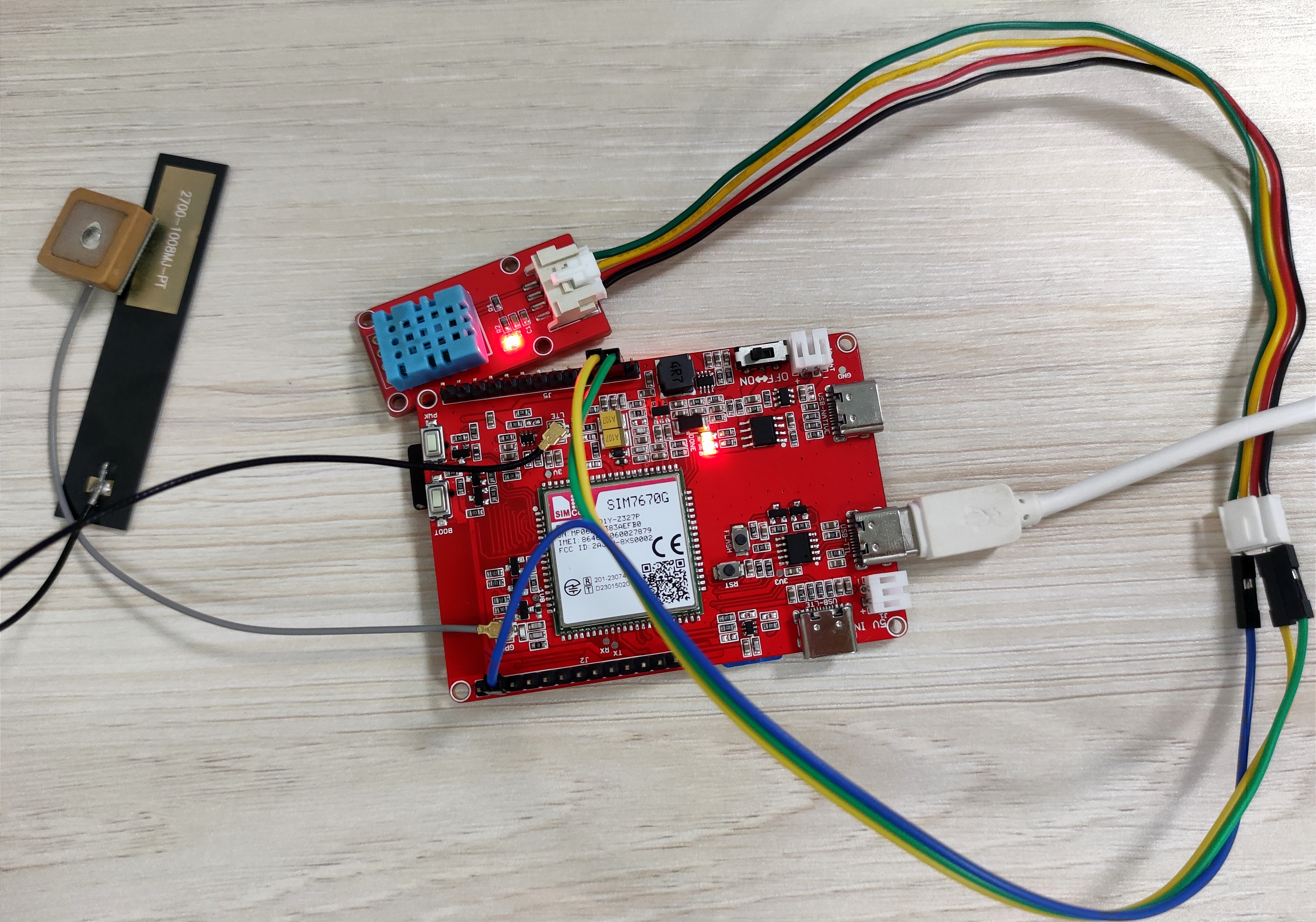
- Prepare a DHT11 module for detecting the temperature and humidity.
- Follow the wiring to connect the DHT11 module and the board.
| DHT11 | ESP32S3 4G LTE module |
|---|---|
| VCC | 3.3V |
| GND | GND |
| DATA | IO2 |
6.1 Thingspeak
To transmit the data to your Thingspeak channel, it has to create a new channel and get the APIKEY information. Then replace the APIKEY in the code with yours.
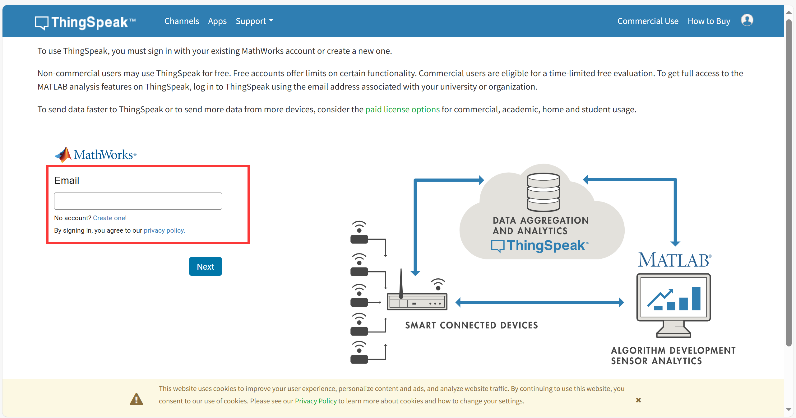
- sign in or sign up for ThingSpeak
If you already have an account, log in and enter the password, otherwise click Create one to register.
- Create new channel
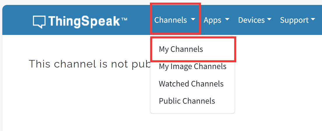
Select "Channel --> My Channels".
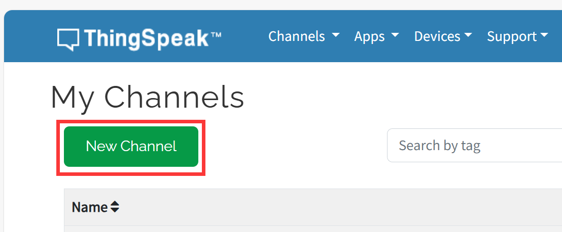
click "New Channel".
Write the name and field information.
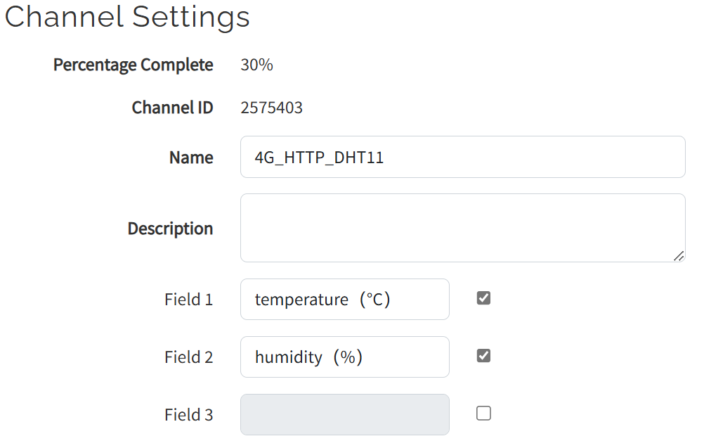
Click Save Channel to create successfully.
6.2 Arduino
-
Open the thingspeak_test by Arduino IDE.
-
Install the library for DHT11 module.
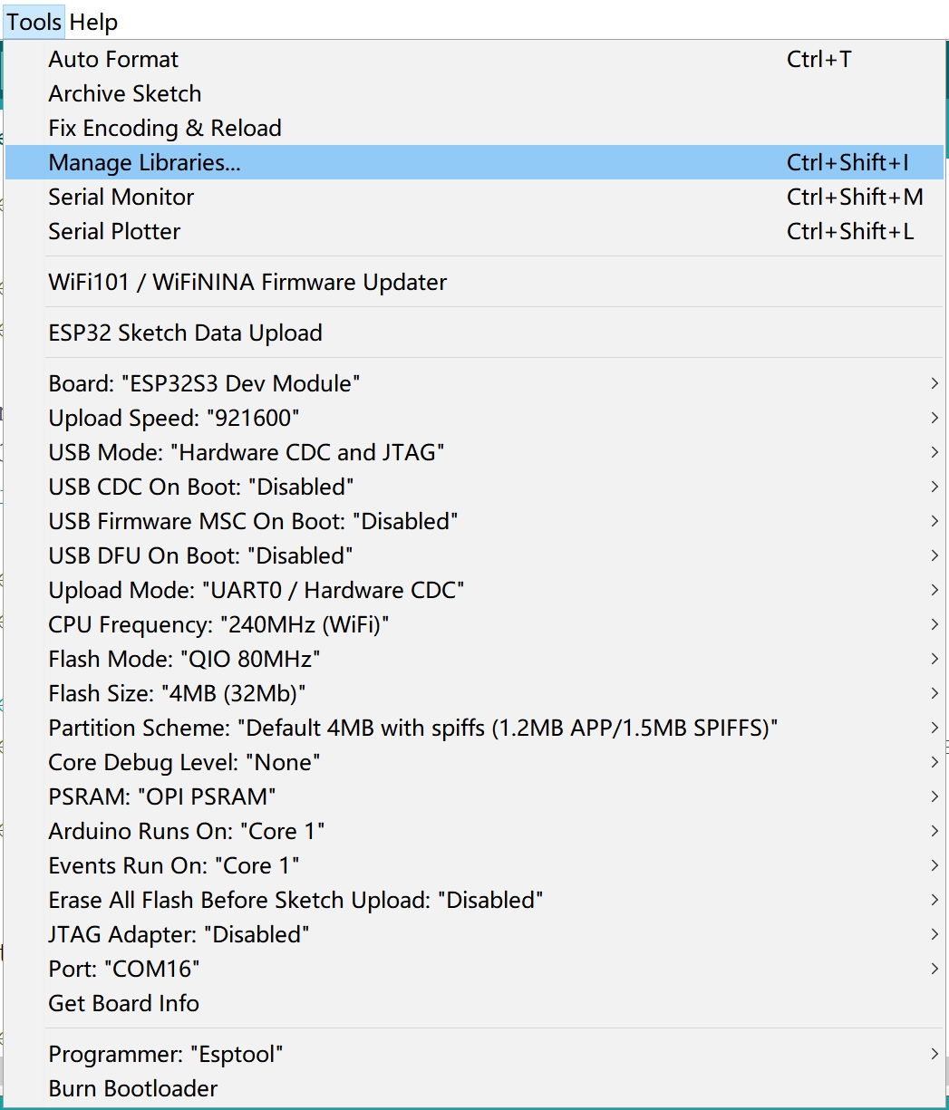
Select "Tools-->Manage Libraries..."
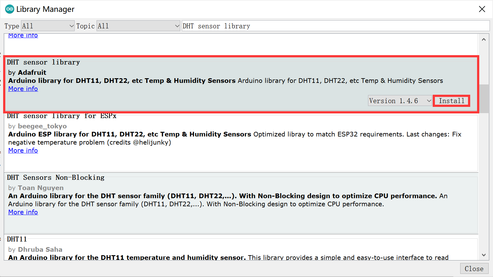
Search "DHT sensor library" and click Install.
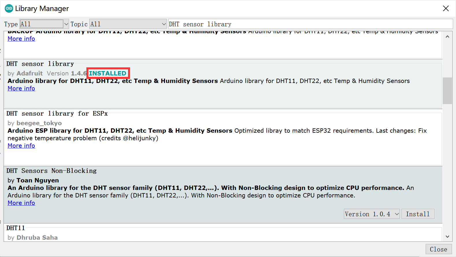
Install successfully.
- Use Type-C USB cable to connect the board and PC, note plug the cable to USB-TTL interface.
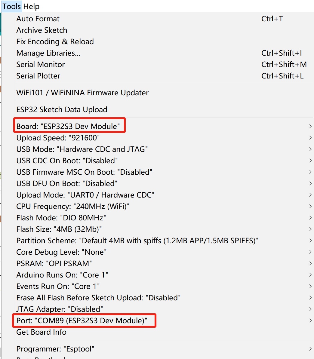
- Select "Tool --> Board --> ESP32S3 Dev Module" and the port
Verify the code and upload.
Note: After the program is uploaded, the STA light on the back of the module will light up. If the light is not on, manually press the PWK button for 2 seconds and release it.
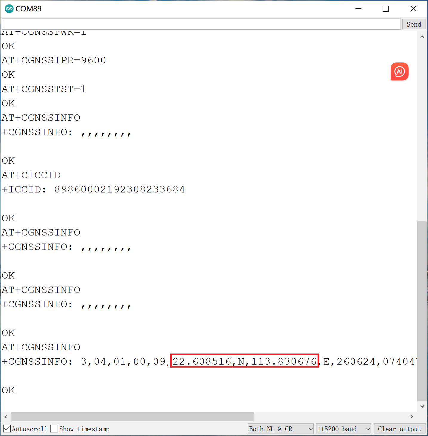
7. GPS test
"AT+CGNSSPWR=1"     //turn the GPS on
"AT+CGNSSIPR=9600"  //Configure the baud rate of UART and GPS module
"AT+CGNSSTST=1"     //Start sending data received from UART to NMEA port
"AT+CGNSSINFO"      //Get GPS infomation
-
Open the GPS_AT_Command by Arduino IDE.
-
Use Type-C USB cable to connect the board and PC, note plug the cable to USB-NATIVE interface.
-
Select "Tool --> Board --> ESP32S3 Dev Module" and the port
Verify the code and upload. When it is successful, open the serial monitor and the serial port will print the GPS information.
Note: This test must be done outdoors, because you cannot receive a GPS signal indoors or in the basement.
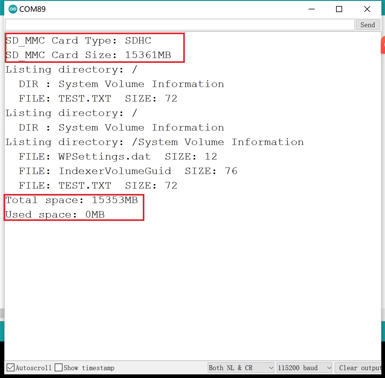
8. Test microSD card of MCU
This is a 4G_SD_Card to SD card test.
-
Open the sketch by Arduino IDE.
-
Use Type-C USB cable to connect the board and PC, note plug the cable to USB-NATIVE interface.
-
Select "Tool --> Board --> ESP32S3 Dev Module" and the port
When it is successful, open the serial monitor and it will print the message of the SD writing and reading.
9. FAQ
You can list your question here or contact techsupport@makerfabs.com for technology support. Detailed descriptions of your question will be helped to solve your question.