Semtech LR1121 LoRa& LoRaWAN Solution with STM32
1.Introduction
The STM32+LR1121 is a high-performance, ultra-low-power, multi-band wireless communication module based on the STM32L476RGT6 32-bit low-power MCU and Semtech's latest-generation LR1121 multi-band LoRa transceiver. It supports Sub-GHz, 2.4GHz, and S-band (1.9–2.1GHz) communication, meeting the diverse requirements of IoT applications for long-range, low-power, and global frequency compatibility.
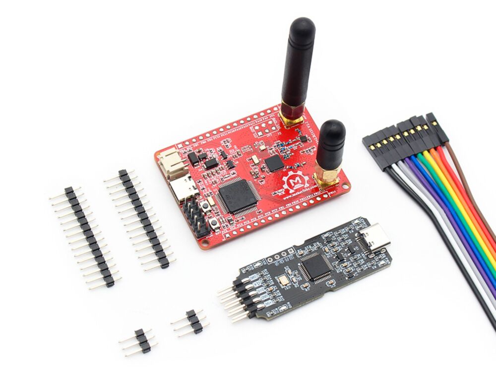
Model:LR11STMV1
2.Features
- Controller: STM32L476RGT6(Cortex-M4, 1MB Flash, 128KB SRAM).
- RF Transceiver: Semtech LR1121.
- Support Protocols: LoRa, (G)FSK, Sigfox, LR-FHSS.
- Support Frequency Bands: 150–960 MHz, 1.9-2.1GHz Satellite band and 2.4GHz ISM bands.
- Interfaces: SPI, UART, I2C, GPIO, ADC
3.Usage
Before getting started, the LR1121 must be programmed with firmware. Depending on the application, two types of firmware are available: LoRa mode and LoRaWAN mode.
LR1121 Firmware Flashing
-
Download the LR1121 firware from github.
-
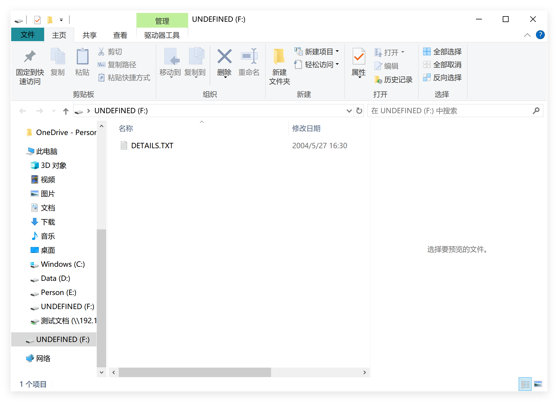
Use STLINK to connect the board and PC, a removable drive will automatically show up.
| STLINK | STM32_LR1121 |
|---|---|
| 3V3 | 3V3 |
| GND | GND |
| RX | TX |
| TX | RX |
| RST | NRXT |
| SWO | SWO |
| CLK | TCK |
| DIO | TMS |
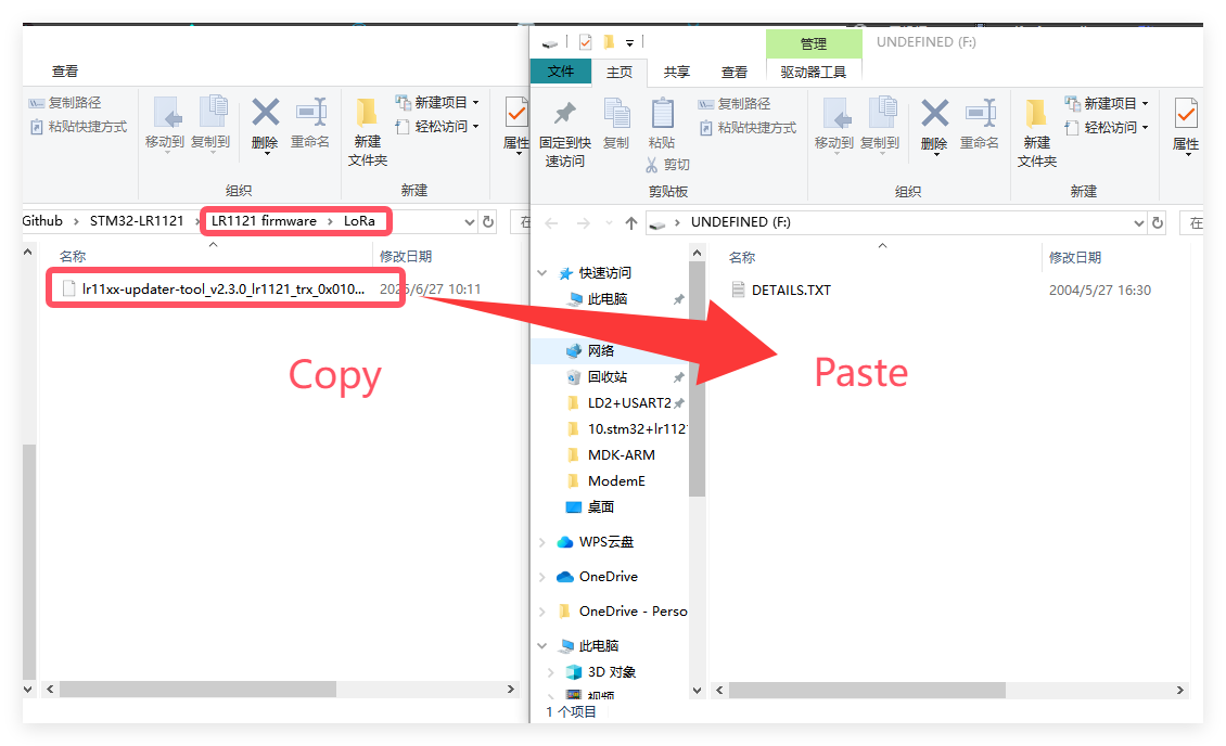
- If you want to work in LoRa mode, copy the firmware to the drive. Once the drive automatically reappears, the flashing process is complete.
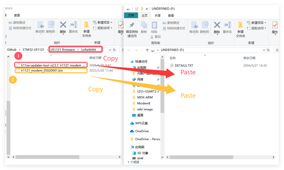
- If you want to work in LoRaWAN mode, First copy the "lr11xx-updater-tool_v2.5.1_lr1121_modem_v2.0.1.bin" to the drive, waitting the drive reappears, then copy the "lr1121_modem_05020001.bin" to the drive to complete the firmware flashing process.
3.1 LoRa
3.1.1 Work_with_another_board
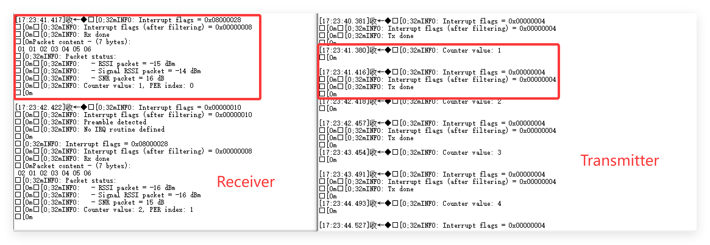
The LoRa example is a basic point-to-point communication demo. It requires two boards, one as the transmitter and the other as the receiver. The transmitter continuously sends an incrementing number, which is received and displayed by the receiver.
-
Download the LoRa code from github, The default mode is transmitter mode.
-
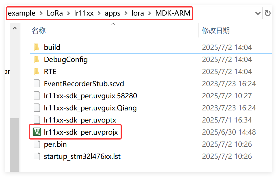
Open the project by keil.
-
Use STLINK to connect the board and PC,
-
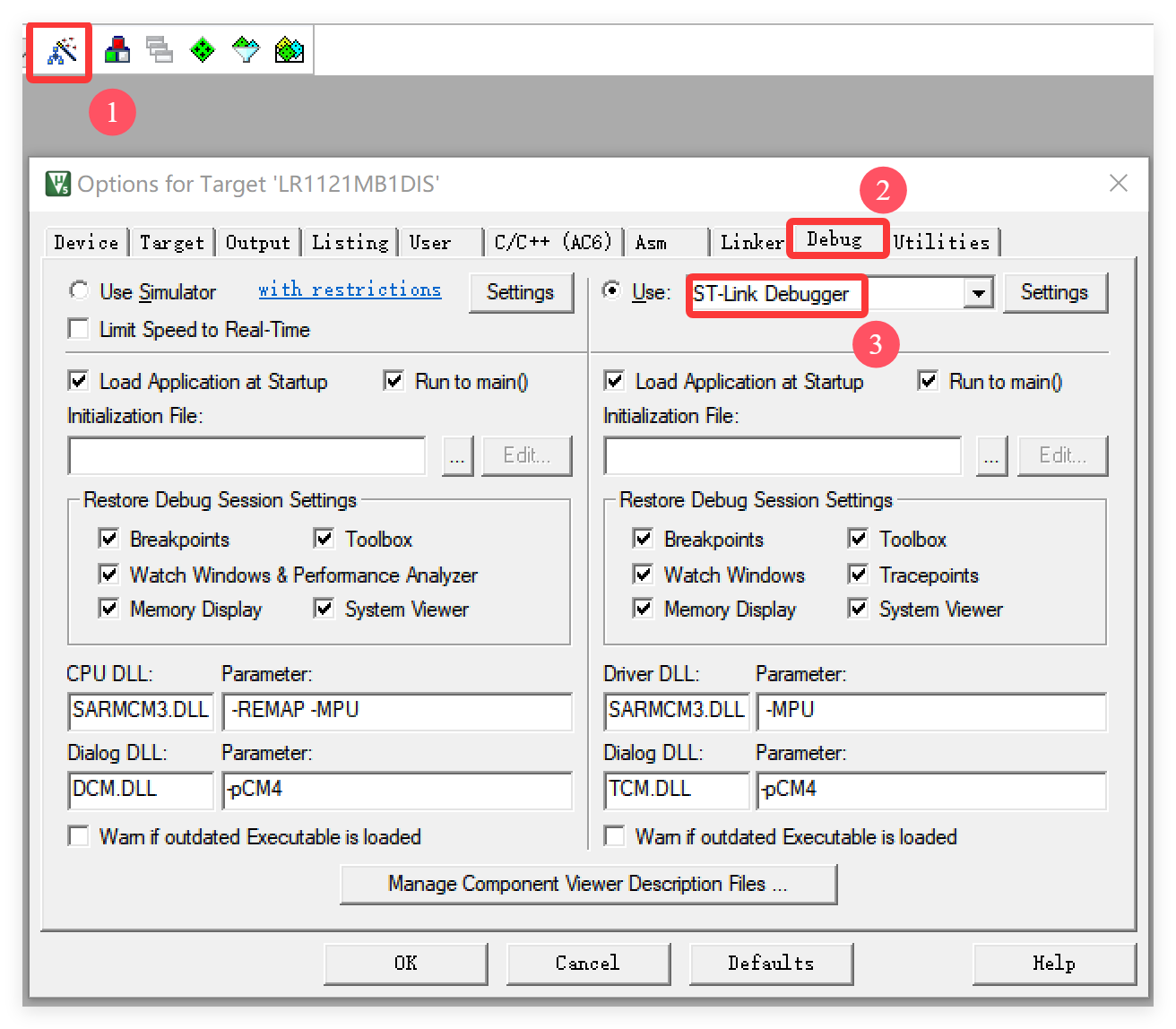
Click "Options for Target..." and select the "ST-Link Debugger"
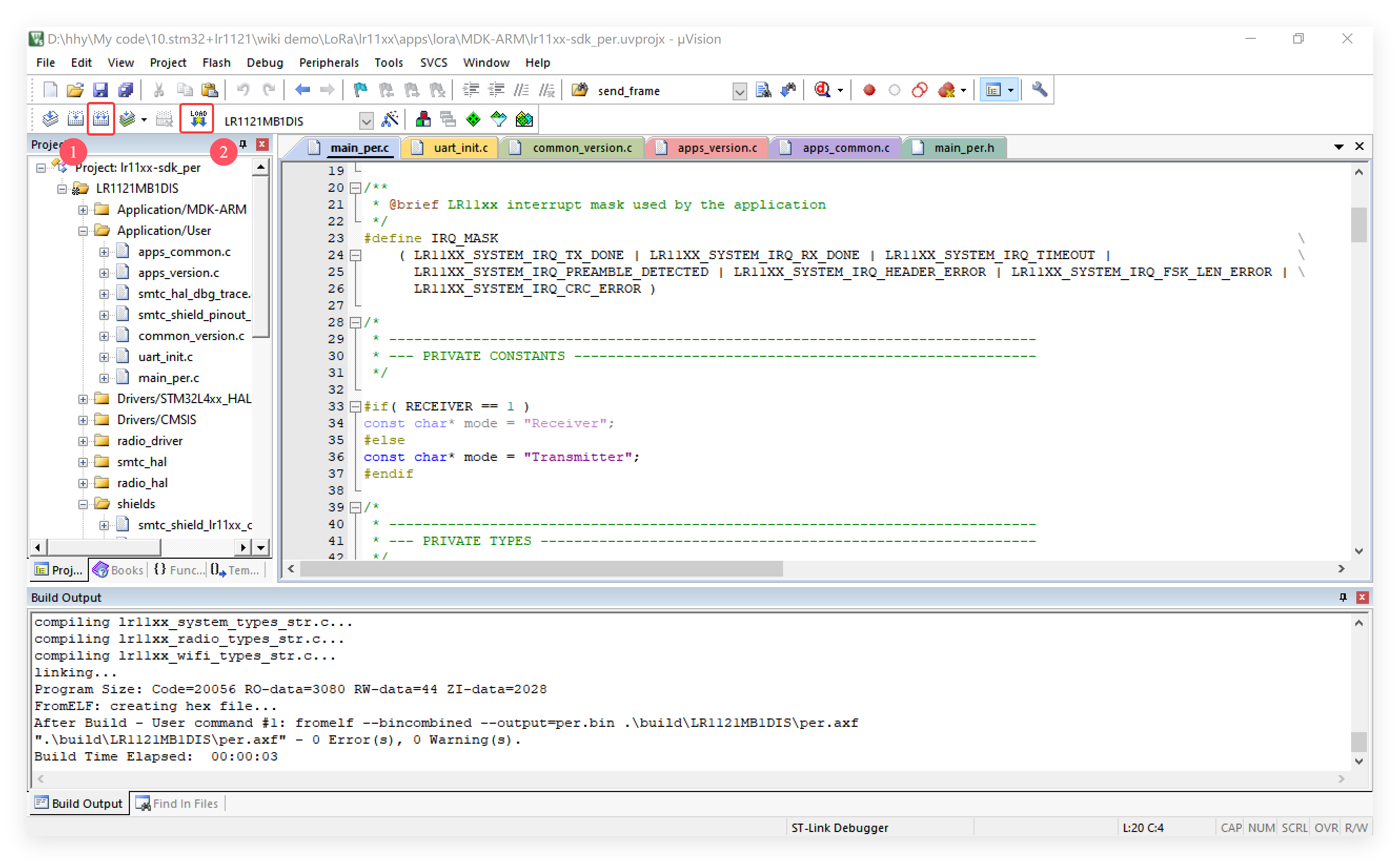
- Click "Rebuild" first and then click "Download".
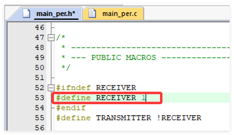
- To switch to receiver mode, change the definition of RECEIVER to 1 in main_per.h. After that, prepare a second board and flash it using the same procedure.
Result
3.1.2 Work with MaLoRa
This example uses the LoRa protocol to communicate with the 4-Channel MOSFET Driver in the MaLoRa series. Users can send predefined commands via the serial port to control the on/off state of the MOSFET channels. Once a command is received, the MOSFET module will respond by sending the real-time control status back to the STM32.
a.STM32+LR1121
-
Download the Work_with_MOS from github.
-
Open the project by keil.
-
Use STLINK to connect the board and PC,
-
Click "Options for Target..." and select the "ST-Link Debugger"
- Click "Rebuild" first and then click "Download".
b.4-Channel MOSFET Driver
-
Open the work_with_lr1121 by Arduino.
-
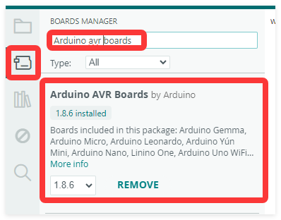
Install Arduino AVR Boards v1.8.6
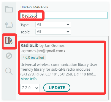
- Install RadioLib v4.6.0
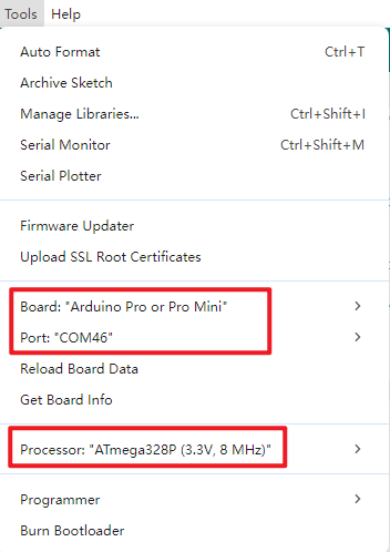
- Use CP2104 USB to Serial Converter to connect the board and PC, and select the development board "Arduino Pro or Pro mini(3.3V, 8MHz)" and the port.
- Verify and upload the code.

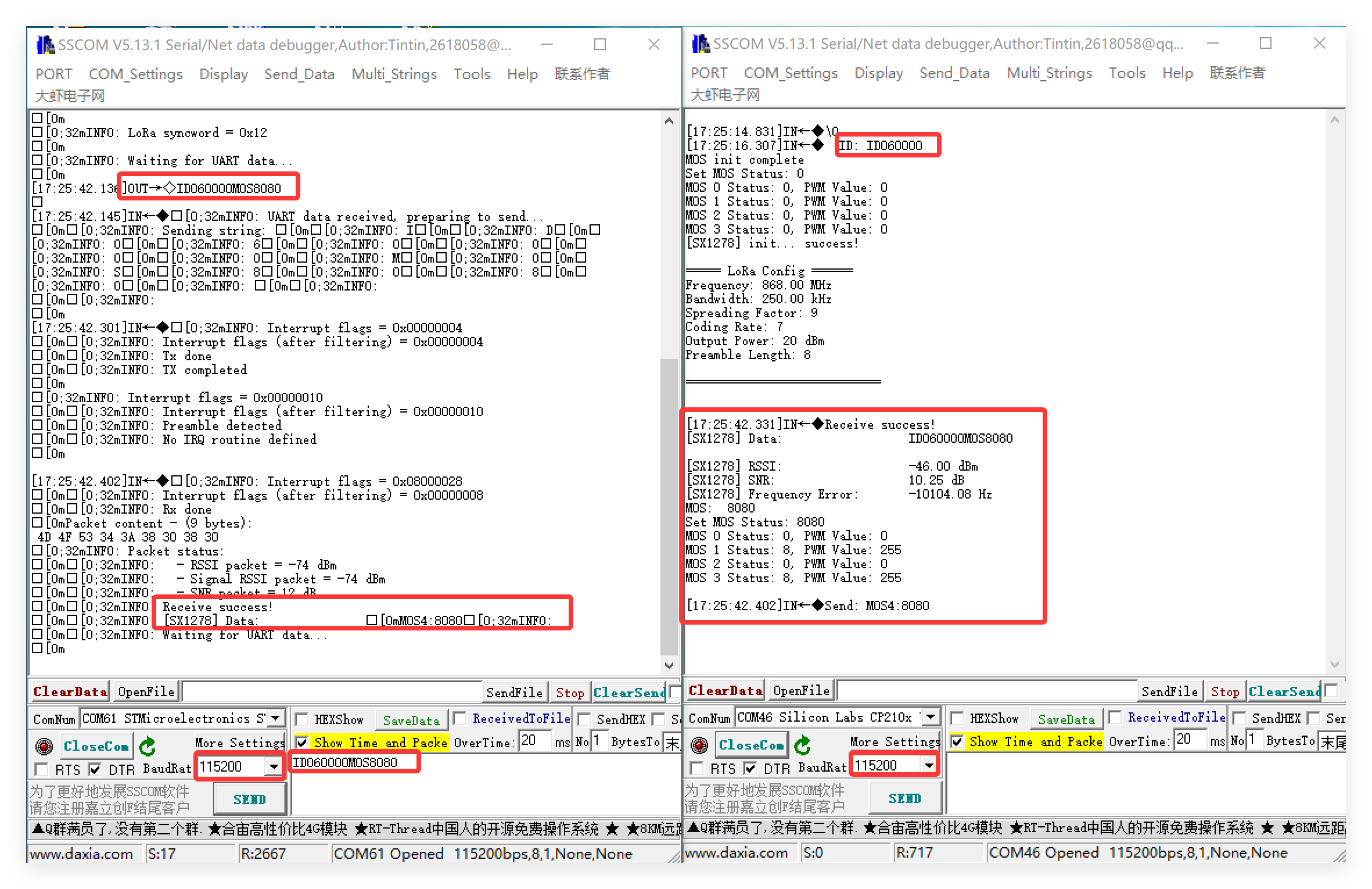
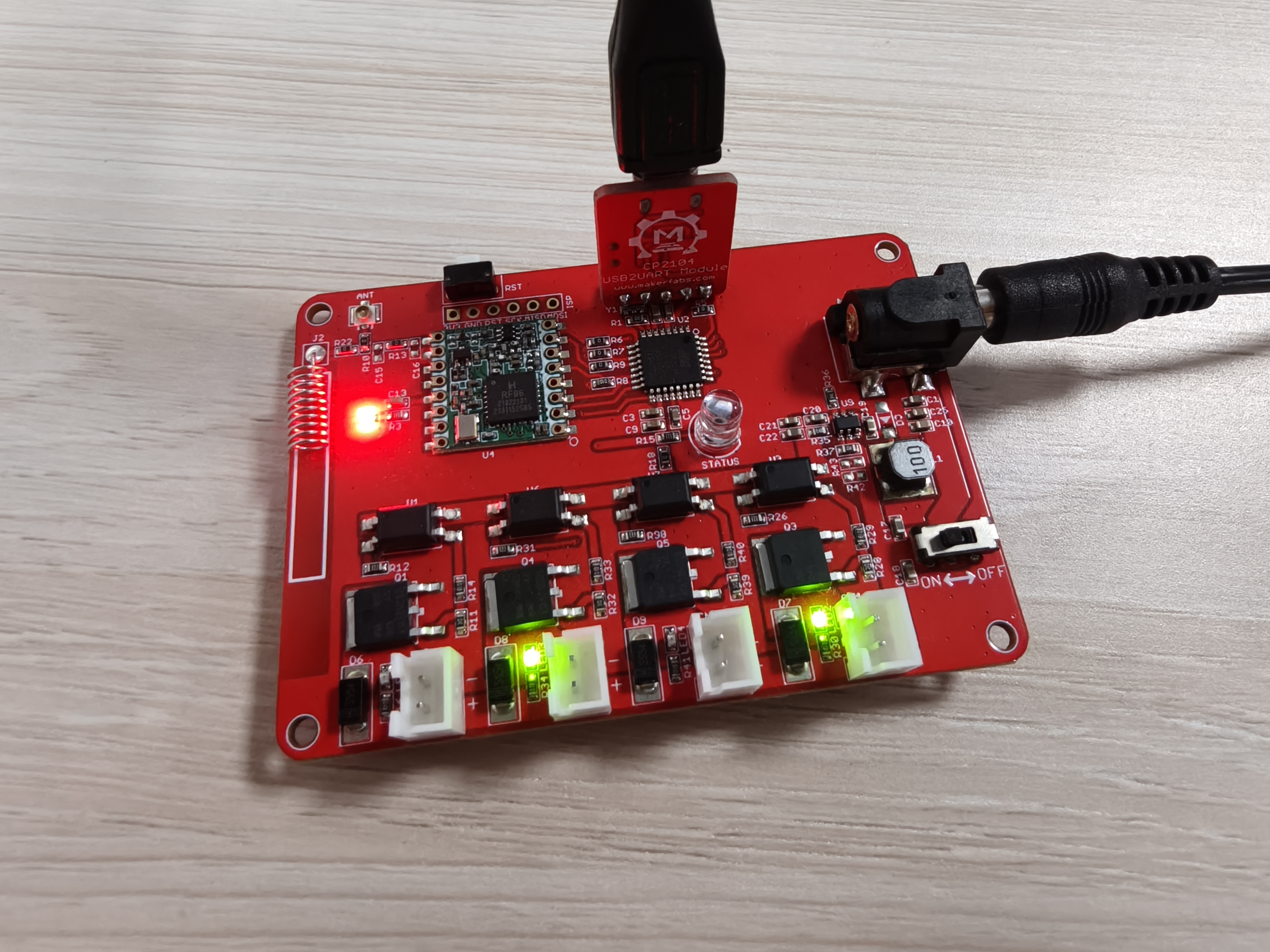
Result
Open the serial monitor, set the baud rate to 115200, and send the fixed format: ID+Your MOS ID+MOS+Your Control. For example: ID060000MOS8080.
Note: MOS ID default is 060000; "Your Control" is represents the status control of the four MOSFET channels, where 0 means OFF and 8 means ON.
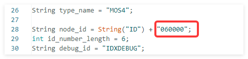
Note:If you need to change the MOSFET ID to match your specific board, you can modify it in the corresponding section of the code.
3.2 LoRaWAN
The LoRaWAN example reads data from a DHT11 and transmits the temperature and humidity to The Things Network (TTN) via LoRaWAN.
Tip: Before using, you must first flash the LoRaWAN-compatible firmware. Please refer to the Usage section for detailed instructions.
3.2.1 Gateway Setup
In this example, temperature and humidity data are collected using a DHT11 sensor, then packaged and transmitted via LoRa to a local gateway, which forwards the data to The Things Network (TTN). The project uses a LoRaWAN gateway from Seeed Studio; for detailed configuration instructions, please refer to the Wiki.
3.2.2 Flashing the code
Wiring schematic:
| Board | DHT11 |
|---|---|
| PC10 | DATA |
| 3V3 | VCC |
| GND | GND |
-
Wire the DHT11 to your board as schematic above.
-
Download the LoRaWAN code from github.
-
Open the project by keil.
-
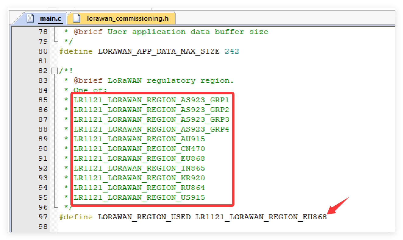
Set "LORAWAN_REGION_USED" according to your regional frequency band, take 868 for example.
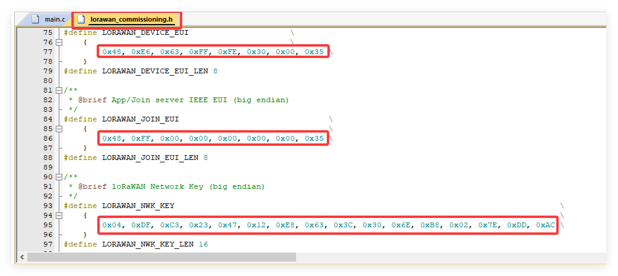
- Modify the device credentials (DevEUI, JoinEUI, and AppKey) in lorawan_commissioning.h to match your own.
-
Use STLINK to connect the board and PC,
-
Click "Options for Target..." and select the "ST-Link Debugger"
- Click "Rebuild" first and then click "Download".
3.2.3 TTN and ThingSpeak
TTN Configuration
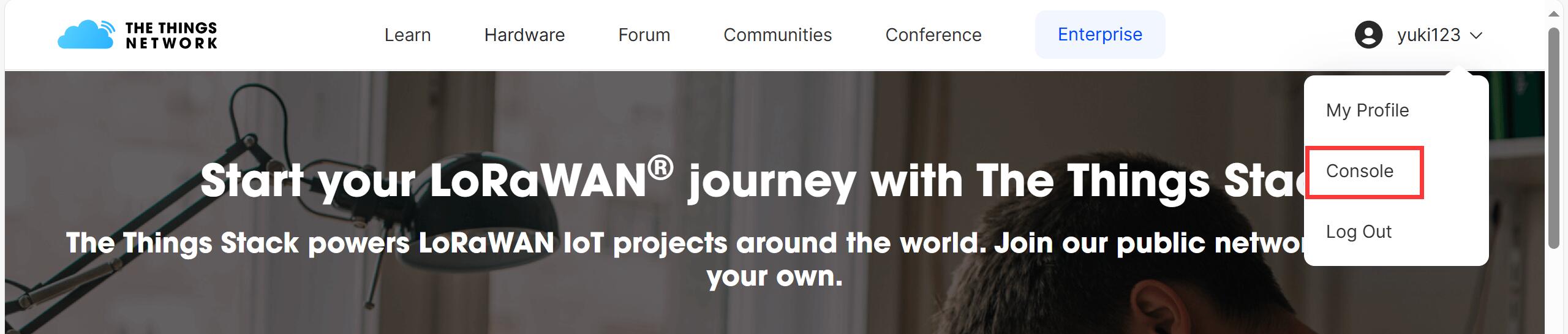
- Open The Things Network and register an account.
-
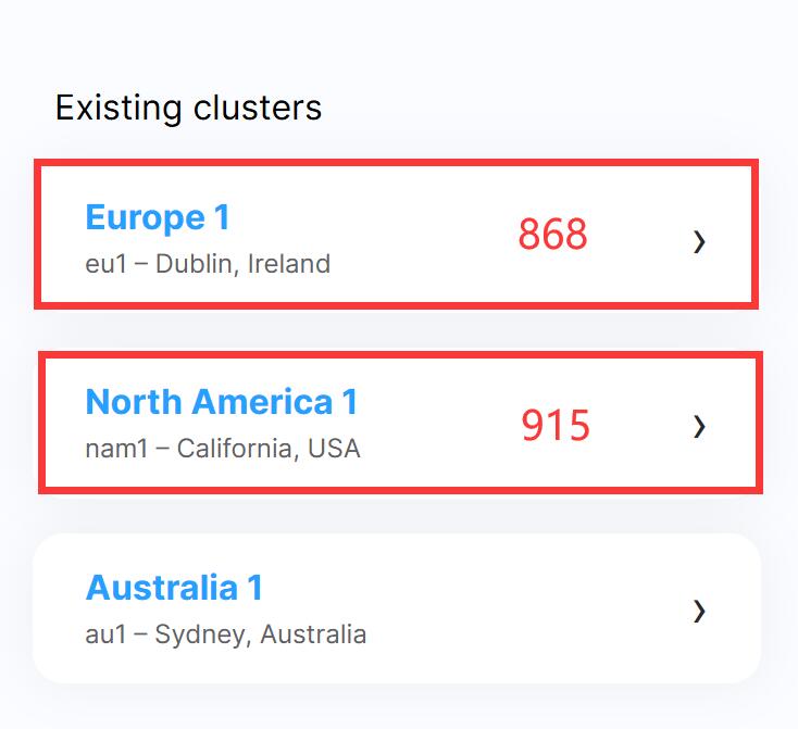
Select the correct region.
-
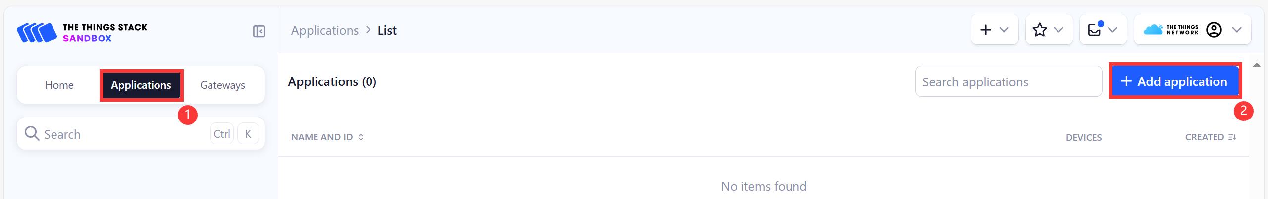
Create new application.
-
Enter your Application ID, and click "Create application"

-
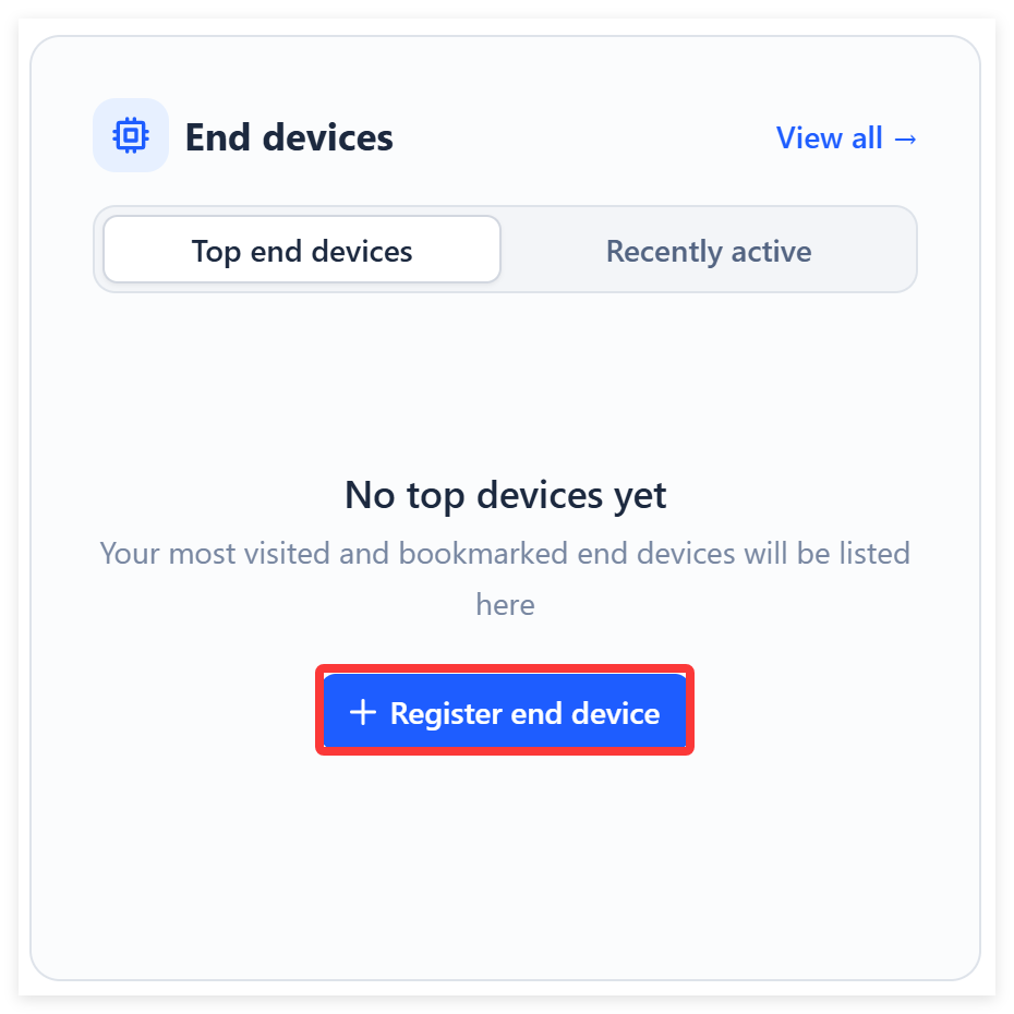
Click "+ Register end device"
-
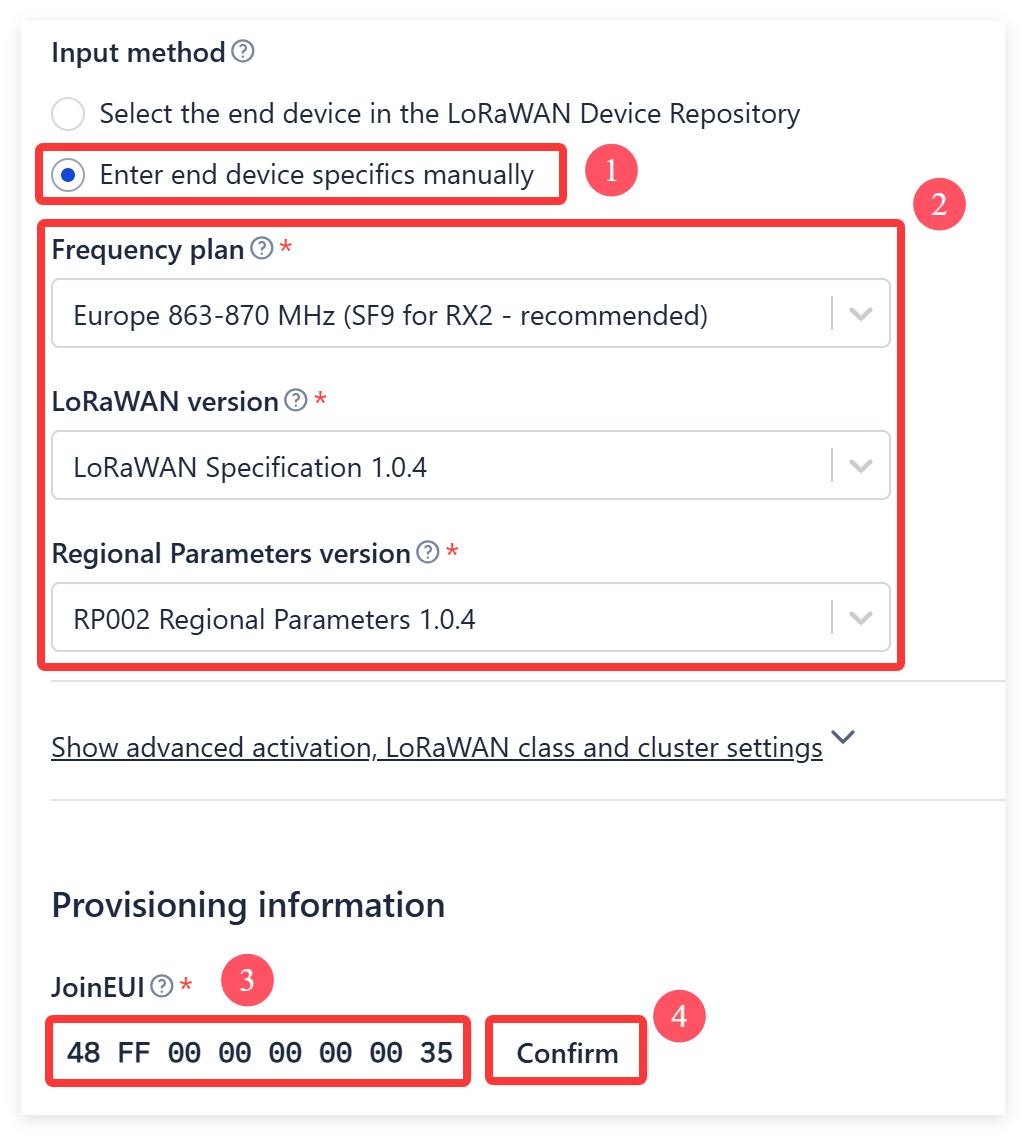
Choose "Enter end device specifics manually"
- Select the three options as shown in the image below.(Take 868 for example)
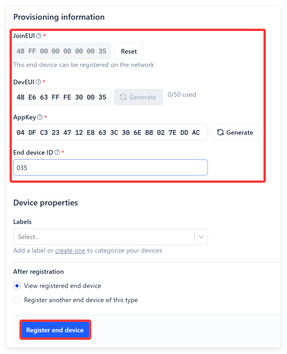
- Enter you joinEUI, DevEUI, Appkey data.
| CREDENTIALS | <--> | Provisioning information |
|---|---|---|
| LORAWAN_JOIN_EUI | <--> | JoinEUI |
| LORAWAN_DEVICE_EUI | <--> | DevEUI |
| LORAWAN_NWK_KEY | <--> | AppKey |
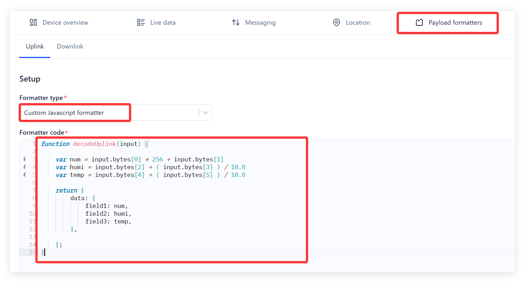
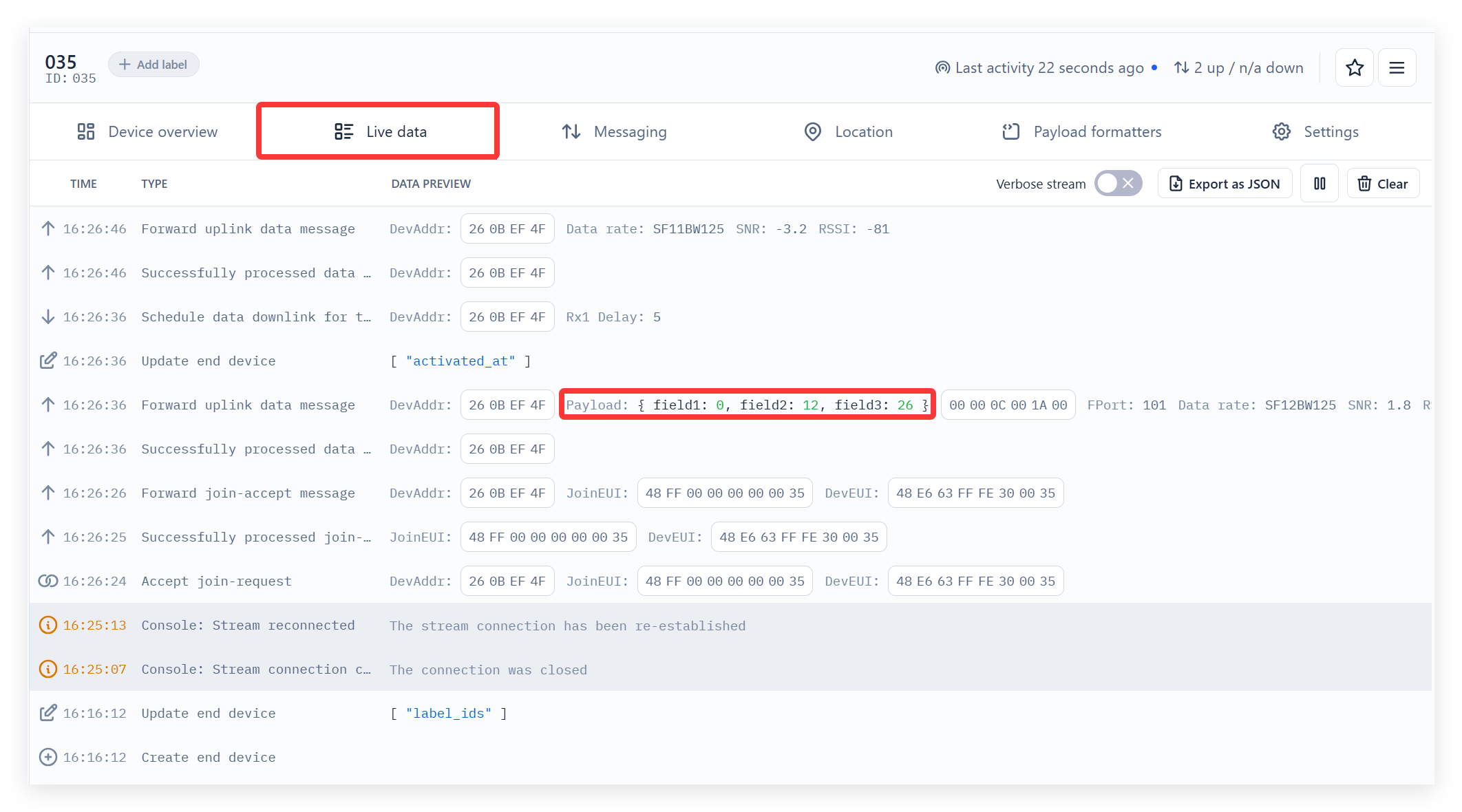
- Click “Payload Formatters-->Uplink”.
- Select “Custom JavaScript Formatters”.
- Write JavaScript code to parse the binary data sent from the device.
function decodeUplink(input) {

    var num = input.bytes[0] * 256 + input.bytes[1]
    var humi = input.bytes[2] + ( input.bytes[3] ) / 10.0
    var temp = input.bytes[4] + ( input.bytes[5] ) / 10.0

    return {
        data: {
            field1: num,
            field2: humi,
            field3: temp,
        },

    };
}
-
Finally click "Save changes".
-
Press "RES" button and you will see the data successfully upload to TTN.
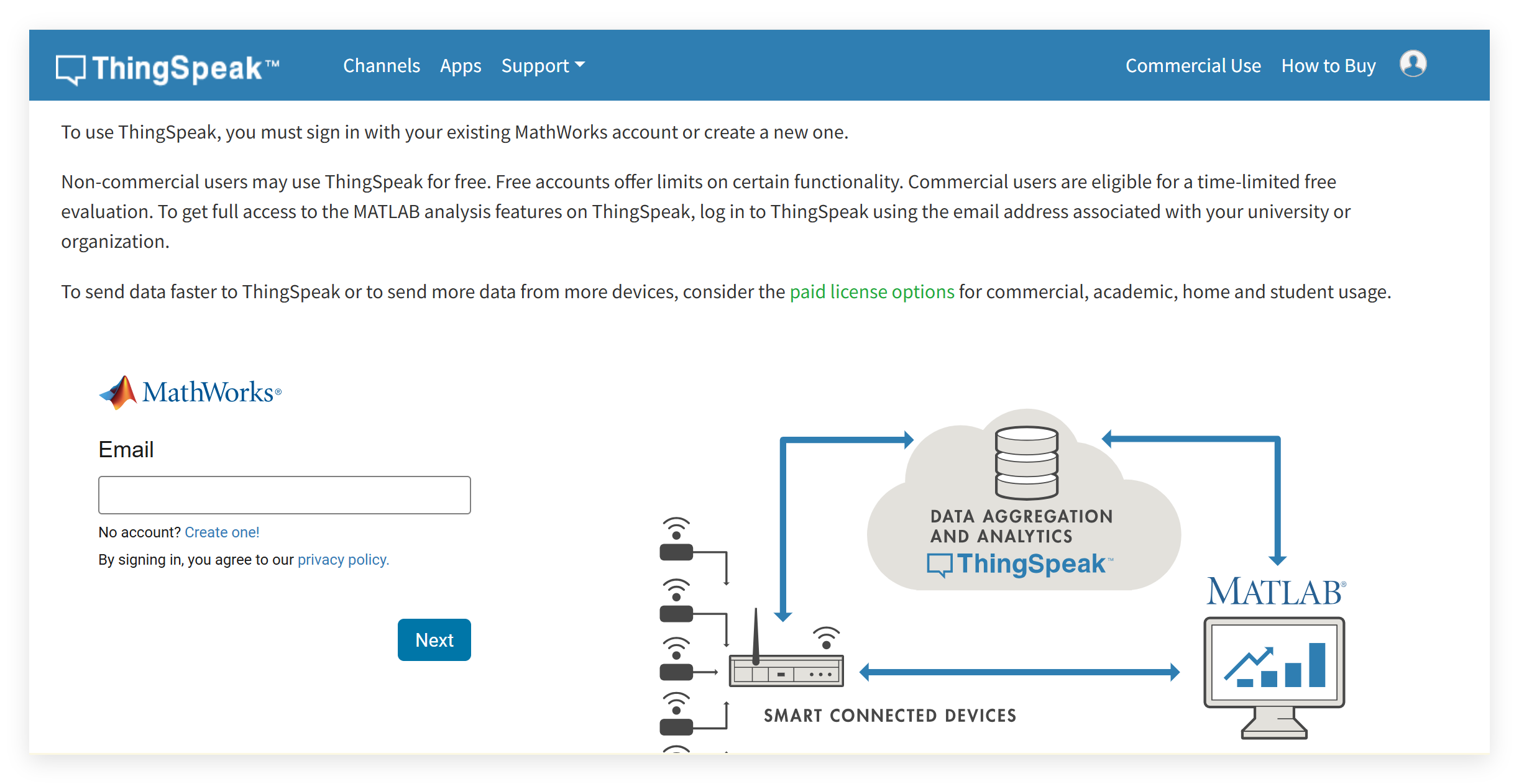
Data Parsing to ThingSpeak
- Open ThingSpeak and register an account.
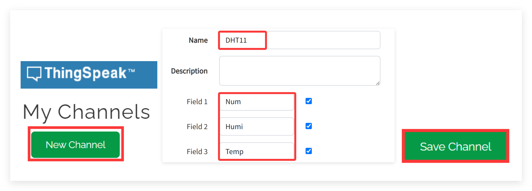
- Click “New Channel”, fill in the Channel name and field names and click “Save Channel”.
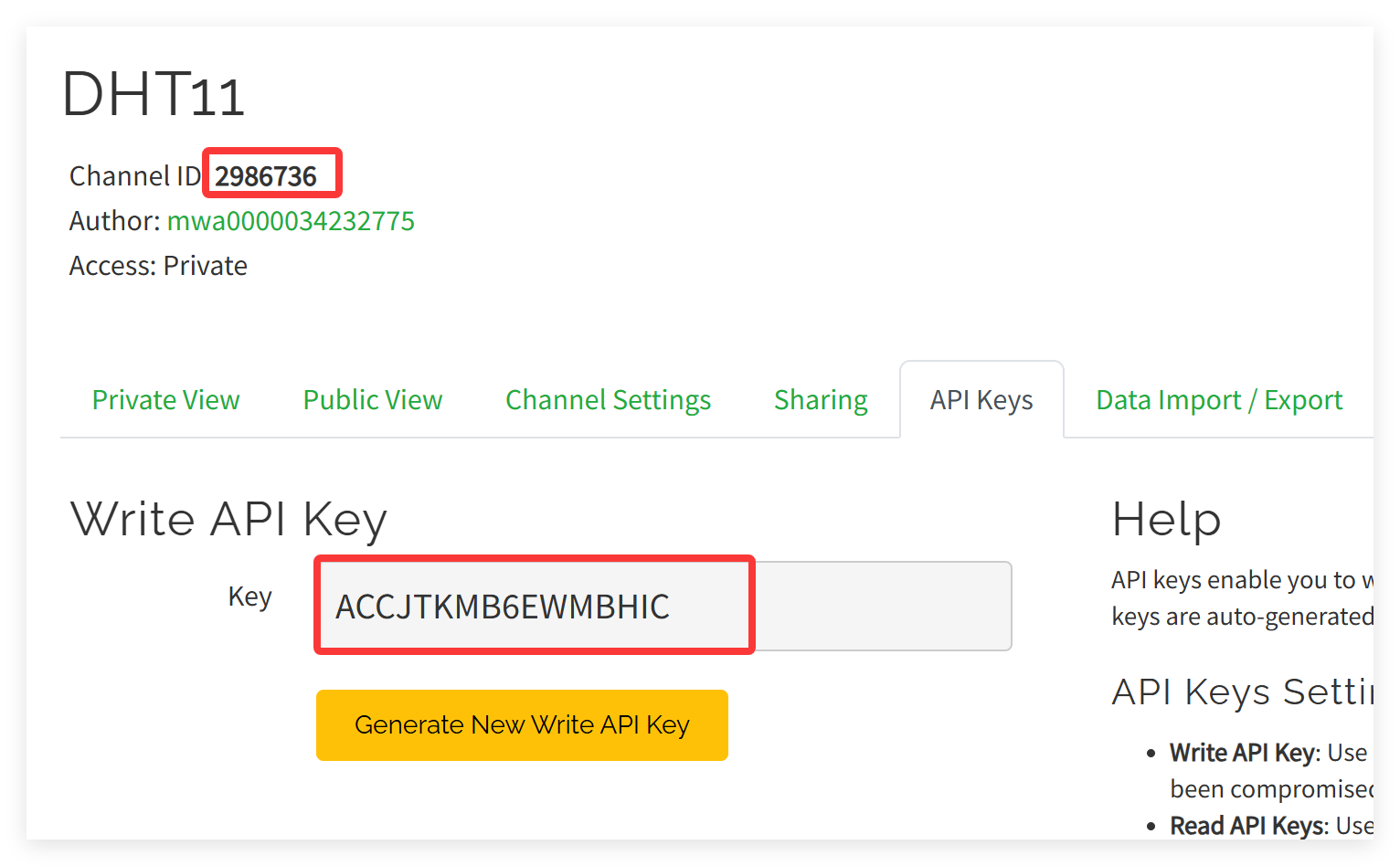
- After successful creation, copy the Channel ID and API Key.
- In the TTN, click “Webhooks” --> “+ Add webhook”.
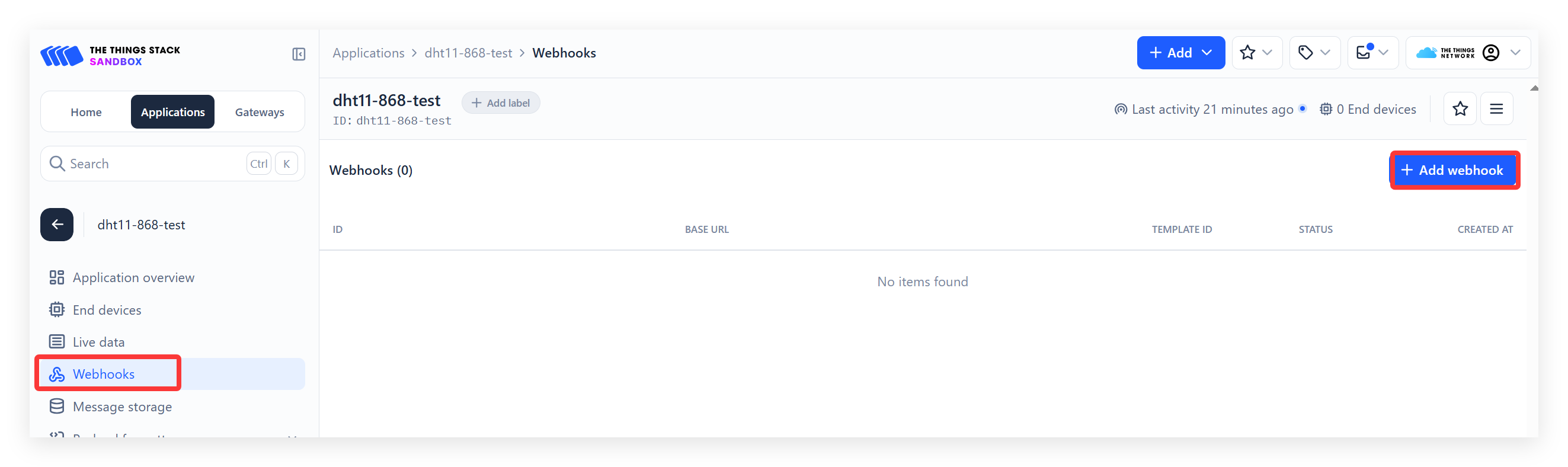
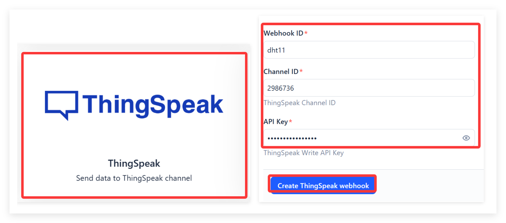
- Select “ThingSpeak”, Fill in the Webhook ID and paste the Channel ID and API Key, click “Create ThingSpeak Webhook”.
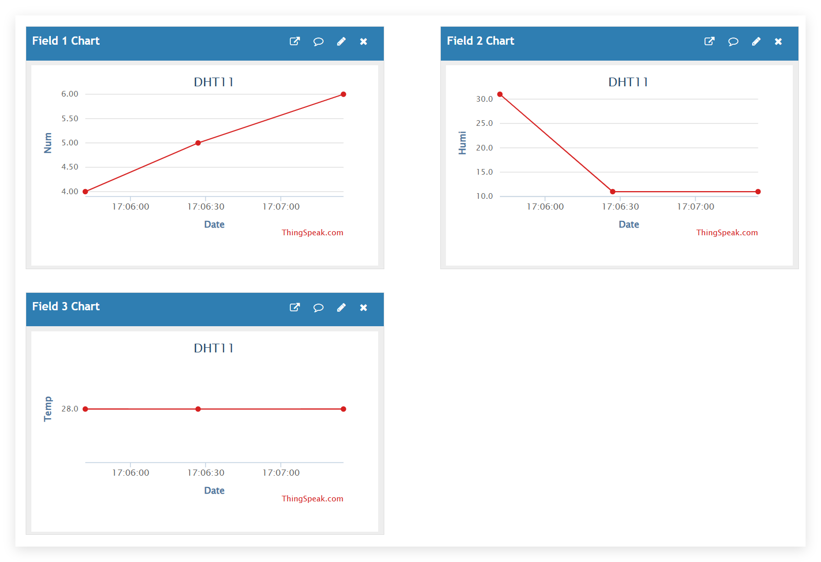
- Press RES button, wait about a minute, you will successfully see the data in ThingSpeak.
4.FAQ
You can list your question here or contact techsupport@makerfabs.com for technology support. Detailed descriptions of your question will be helped to solve your question.
All LR1121 radio driver code and reference implementations used in this project are derived from Semtech’s official GitHub repository. For more information and updates, please refer to the repository.