ESP32 S3 4G LTE CAT1 A7670X
1. Introduction
The Maduino Zero SIM7600 CAT-4 which is based on SIMCOM7600(CAT4) got many 5-stars in the past, but we got much feedback on the price because the CAT-4 module SIM7600 cost high, especially in many IOT project where CAT-4 are not essential. So, now our this new ESP32S3 4G LTE(A7670) have features: 1. Lower Price: this module is based on A7670 4G module, CAT1, its price much lower, while the CAT1 fits for IOT applications such as Remote sensor monitoring; 2. With ESP32S3 controller, it features WIFI/Bluetooth, that can be used for local application setting (with phone) , fit for applications such as shared bike.
Model: ESPA7670
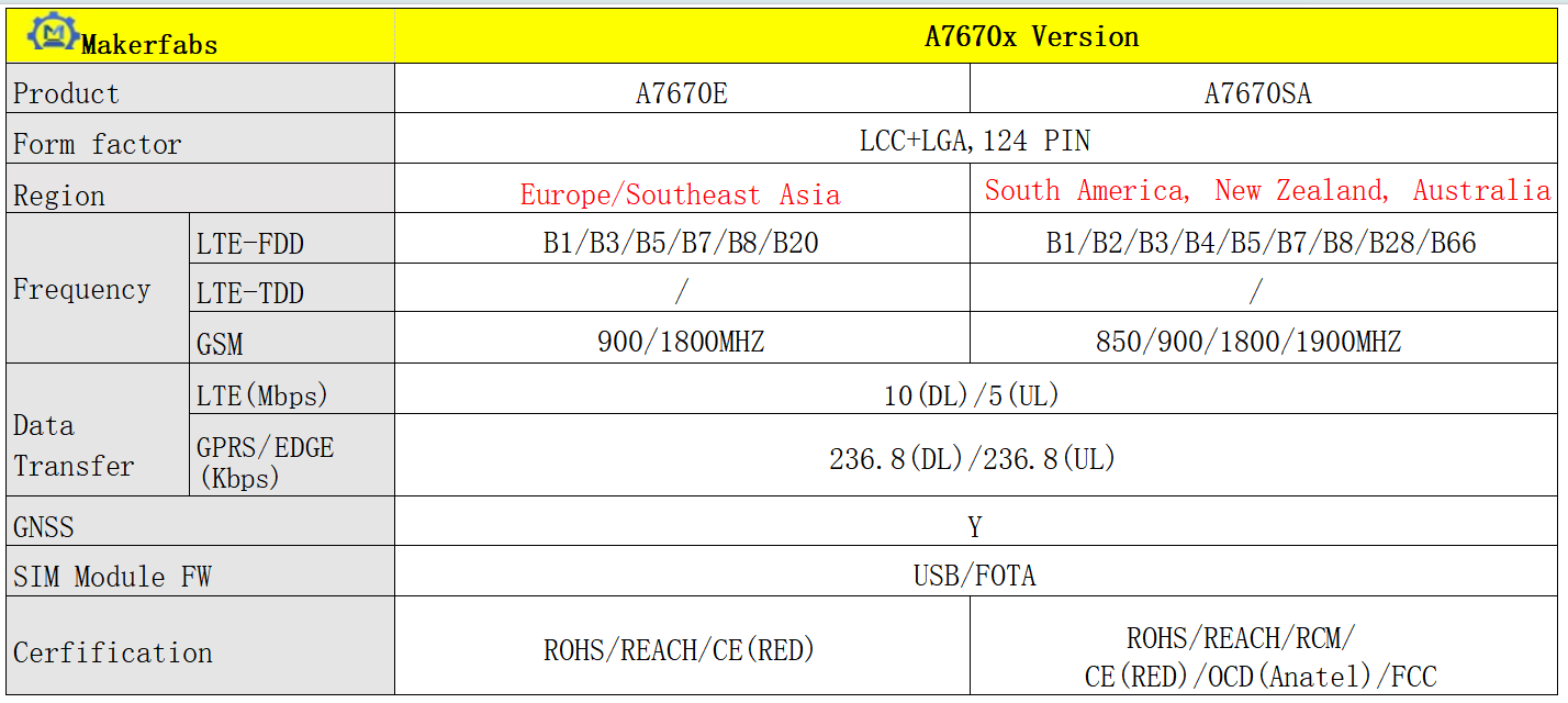
Note: 1. there are E/SA versions, Please check in detail as your location and select the proper solution. 2. as A7670 is not registered in the USA, so not support the USA network currently, for USA users, please use the SIM7600 version
Frequency bands
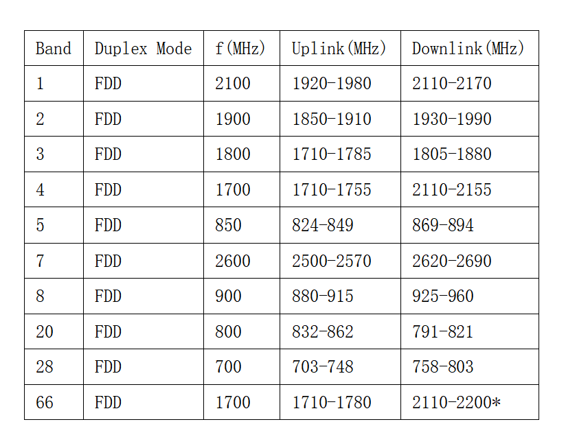 Note: Downlink between 2180–2200 MHz restricted to intra-band Supplemental Downlink
Data comes from wiki
Here is a referenced LTE band list: List of LTE networks
2. Features
- LTE Cat-1, with uplink rate 5 Mbps and downlink rate 10 Mbps;
- Control Via AT Commands
- GNSS Positioning;
- Controller: ESP32-S3-WROOM-1, PCB Antenna, 16MB Flash, 8MB PSRAM, ESP32-S3-WROOM-1-N16R8;
- 3 USB type-C:ESP32S3 USB Native;ESP32S3 USB TTL;A7670 USB
- Audio Support;
- Supports dial-up, phone, SMS, TCP, UDP, DTMF, HTTP, FTP, and so on;
- USB supply voltage range: 4.8~5.5V, 5.0V Typically;
- Battery supply voltage range: 3.4~4.2V, 3.7V Typically;
- Onboard charger, up to 1A charge current; Overcharge protection(OCP), 4.3V; Over-discharge protection(ODP), 2.5V;
- SD card socket
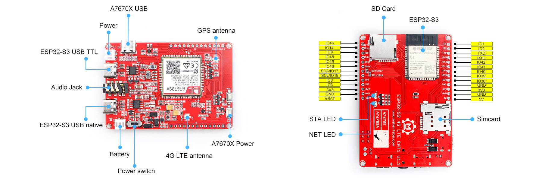
3. Hardware
- Plug the SIM card into the board.
- Plug the GPS antenna into the GPS interface.
- Plug the 4G-GSM antennas into the LTE interface.
- Plug the headphone with the microphone.
- Plug the SD card into the SD card slot.
4. Arduino IDE
- Install the Arduino IDE V1.8.10/V1.8.19
- Use Type-C USB cable to connect the board and PC, note plug the cable to USB-NATIVE interface.
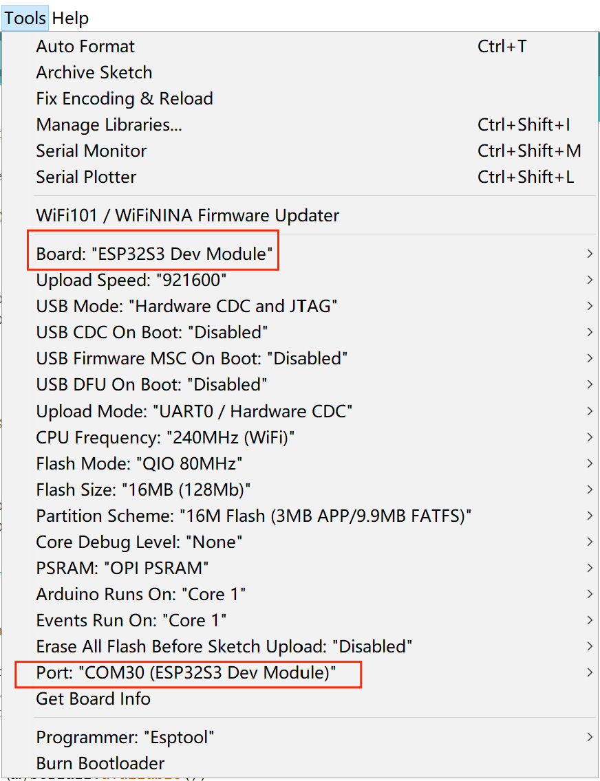
- Select "Tool --> Board --> ESP32S3 Dev Module" and the port
If you haven’t installed the ESP32 Board SDK yet, follow the steps in this guide to get started quickly.
For the ESP32-S3 Development board version, we recommend using versions that have been verified, such as 2.0.8, which is more stable, and less prone to errors.
Note: Different computers may have different port numbers when connecting to a development board. Please select the correct port number based on the development board you are connecting to.
5. Usage
Open the AT_demo by Arduino IDE.
Verify the code and upload.
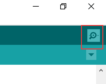
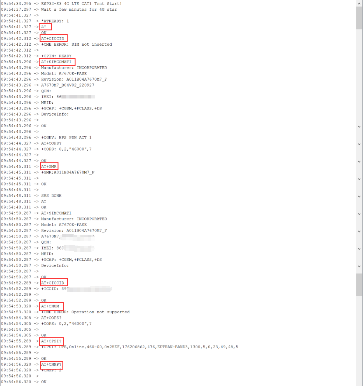
Open the serial monitor, select the "Both NL&CR"and send the AT command to the board, and it will return the module's response.
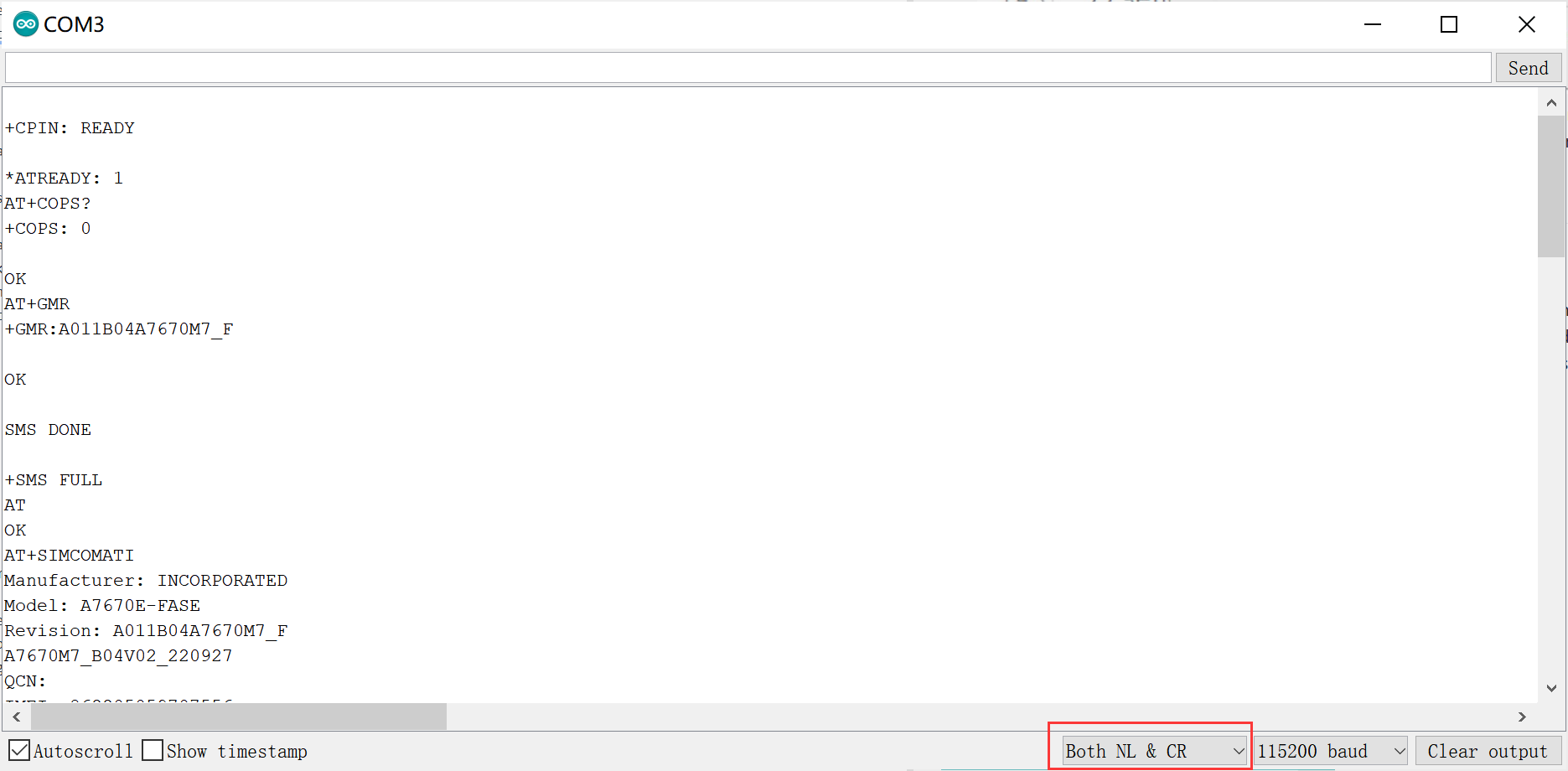
AT+CPIN?     // Request the state of the SIM card
AT+COPS?     // Check the current network operator
AT+GMR       // Request revision identification
AT+SIMCOMATI // Request a total info of the module
AT+CICCID    // Read ICCID from SIM card
AT+CPSI?     // Inquiring UE system information
AT+CNMP?     // Preferred mode selection, 2-Automatic, 13-GSM Only, 14-WCDMA Only, 38-LTE Only
The more AT commmand details you can cheak A76XX_Series_AT_Command_Manual_V1.10.pdf
5.1 Telephone test
AT+CNUM // Request the subscriber number
AT+CSDVC // Switch voice channel device
AT+CSDVC=1 // 1-Handset, 3-Speaker phone
AT+COUTGAIN=2 // Set loudspeaker volume level to 2, the level range is 0 to 7
ATDxxxxx // Call to xxxxx
AT+CHUP // Hang up the call
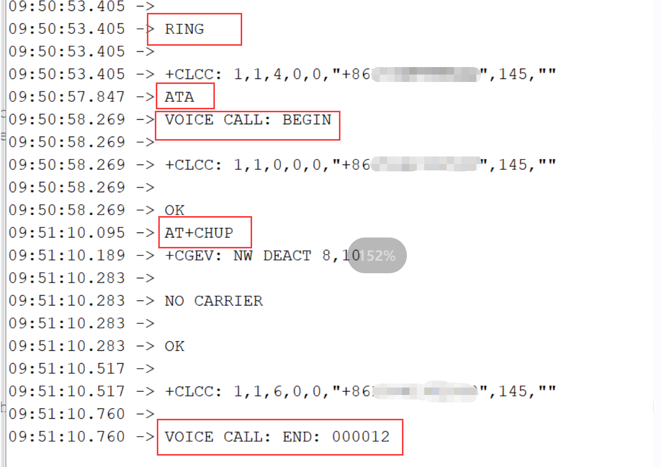
ATA // Call answer
This is a demo to Telophone test.
Open the sketch by Arduino IDE.
Modify the phone number you want to call.
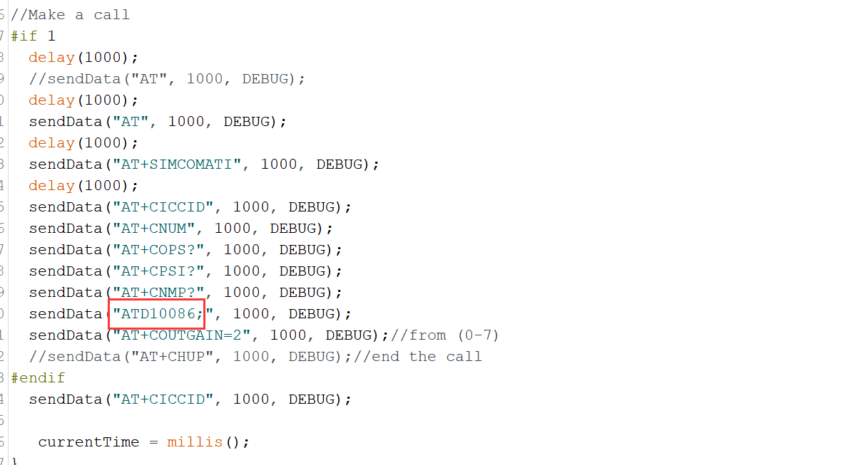
Verify the code and upload. When it is successful, the board will automatically dial the target number and hang up within a few seconds.
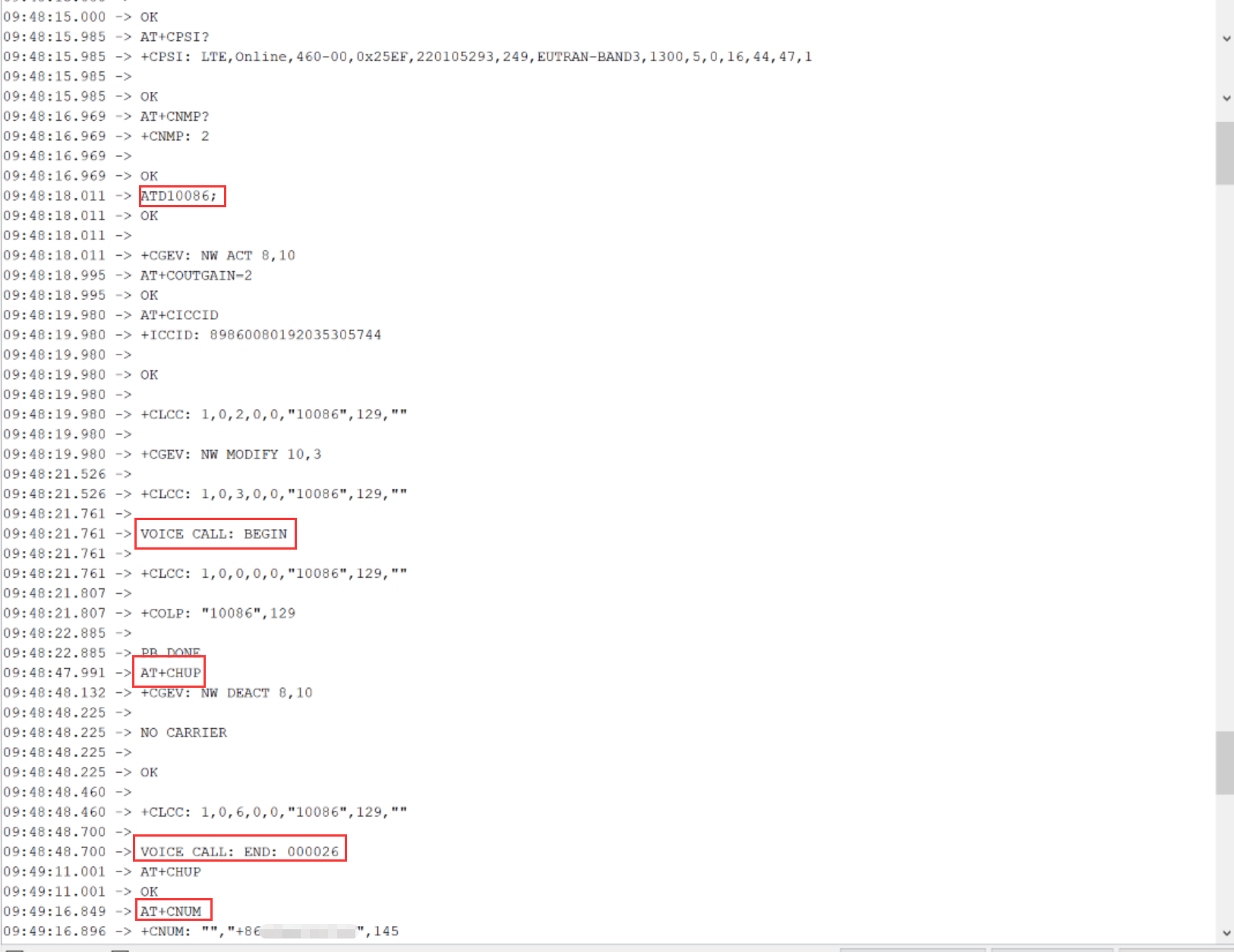
You can also dial the number of the SIM card inserted in the board and manually send the "ATA" via the serial monitor, the board will receive your call.
5.2 HTTP test
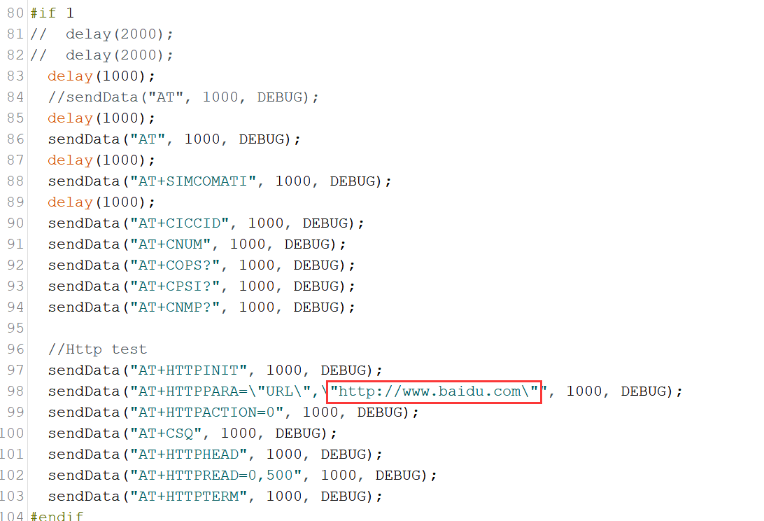
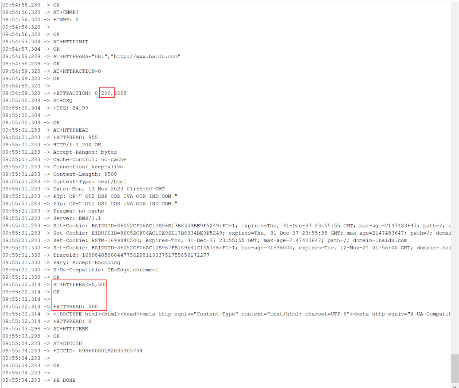
AT+HTTPINIT         // Initialize and start the HTTP
AT+HTTPPARA="URL","http://www.makerfabs.com"  // Set the URL
AT+HTTPACTION=0    // Connect the HTTP. (0-get, 1-post, 2-head)
AT+HTTPHEAD        // Read the response's header.
AT+HTTPREAD=0,500    // Read the content (“500” means the length of data to read)
This is a demo to HTTP test.
Open the sketch by Arduino IDE.
Modify the link to the page you want to connect to.
Verify the code and upload. When it is successful, the serial port will print the web page information, the statuscode of 200 means that the web connection was successful.
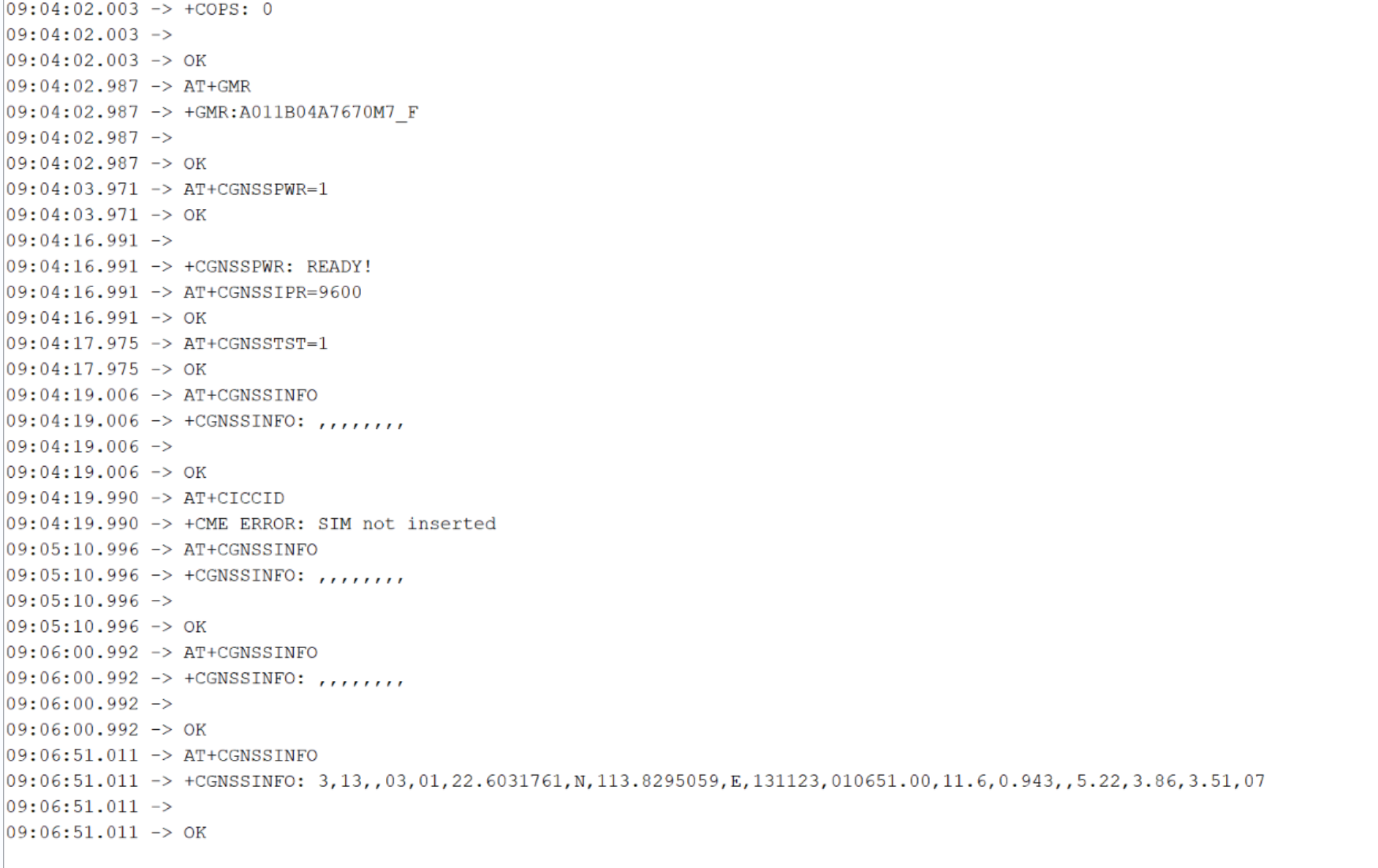
5.3 GPS test
AT+CGNSSPWR         //GNSS power control and AP-Flash control
AT+CGNSSPWR=1       //turn the GPS on
AT+CGNSSIPR=9600    //Configure the baud rate of UART3 and GPS module
AT+CGNSSTST=1       //Send data received from UART3 to NMEA port
AT+CGNSSINFO        //Get GNSS fixed position information
This is a demo to GPS test.
Open the sketch by Arduino IDE.
Verify the code and upload. When it is successful, open the serial monitor and the serial port will print the GPS information.
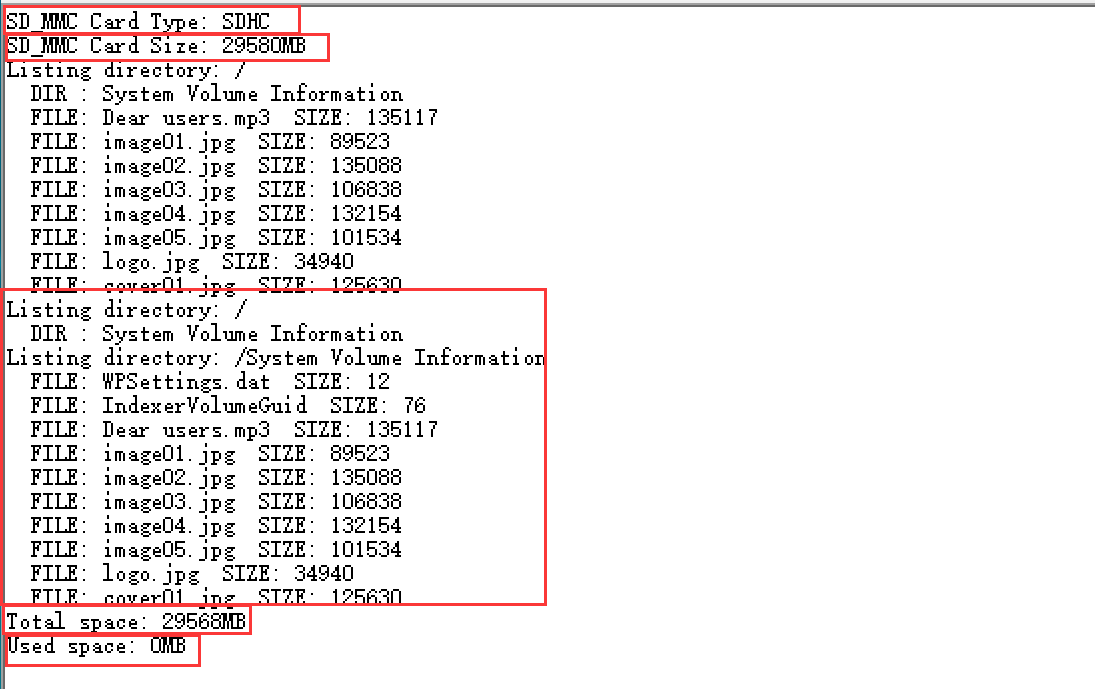
5.4 Test microSD card of MCU
This is a demo to SD card test.
Open the sketch by Arduino IDE.
Verify the code and upload.
When it is successful, open the serial monitor and it will print the message of the SD writing and reading.
6. FAQ
You can list your question here or contact techsupport@makerfabs.com for technology support. Detailed descriptions of your question will be helped to solve your question.