Matouch ESP32-S3 Parallel TFT with Touch 5"
1. Introduction
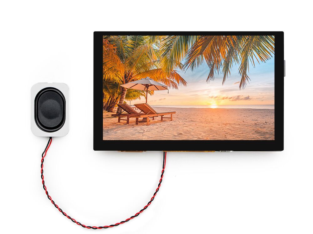
The ESP32 S3 5" IPS display is the ideal display and controller for IoT applications. Its high lightness IPS display with a resolution of 800*480 makes the display effect beautiful, together with feature an IPS screen with detailed and vibrant colours and 5-point capacitive touch, making them particularly suitable for applications such as home automation. The built-in SD card slot allows easy recording and playback of data files, extending the range of possible applications. In addition, the 2 on-board Mabee/Grove interfaces allow users to quickly connect to a variety of sensors for instant creation of personalised prototyping projects.
Model:E32S3RGB5
2. Features
- Controller: ESP32-S3-WROOM-1, PCB Antenna, 16MB Flash, 8MB PSRAM, ESP32-S3-WROOM-1-N16R8
- Wireless: Wifi& Bluetooth 5.0
- LCD: 5 inch High Lightness IPS
- Resolution: 800*480
- LCD interface: RGB 24bit
- Touch Panel: 5 Points Touch, Capacitive
- Touch Panel Driver: GT911
- USB: Dual USB Type-C(one for USB-to-UART and one for native USB)
- USB to UART Chip: CP2104
- Power Supply: USB Type-C 5.0V(4.0V~5.25V)
- Button: Flash button and reset button
- Mabee interface: 1I2C;1GPIO
- MicroSD: Yes
3. Usage in Arduino IDE
- Install the Arduino IDE V1.8.19/V2.3.4 If you haven’t installed the ESP32 Board SDK yet, follow the steps in this guide to get started quickly.
For the ESP32-S3 Development board version, we recommend using versions that have been verified, such as 2.0.16, which is more stable, and less prone to errors.
Note: Different computers may have different port numbers when connecting to a development board. Please select the correct port number based on the development board you are connecting to.
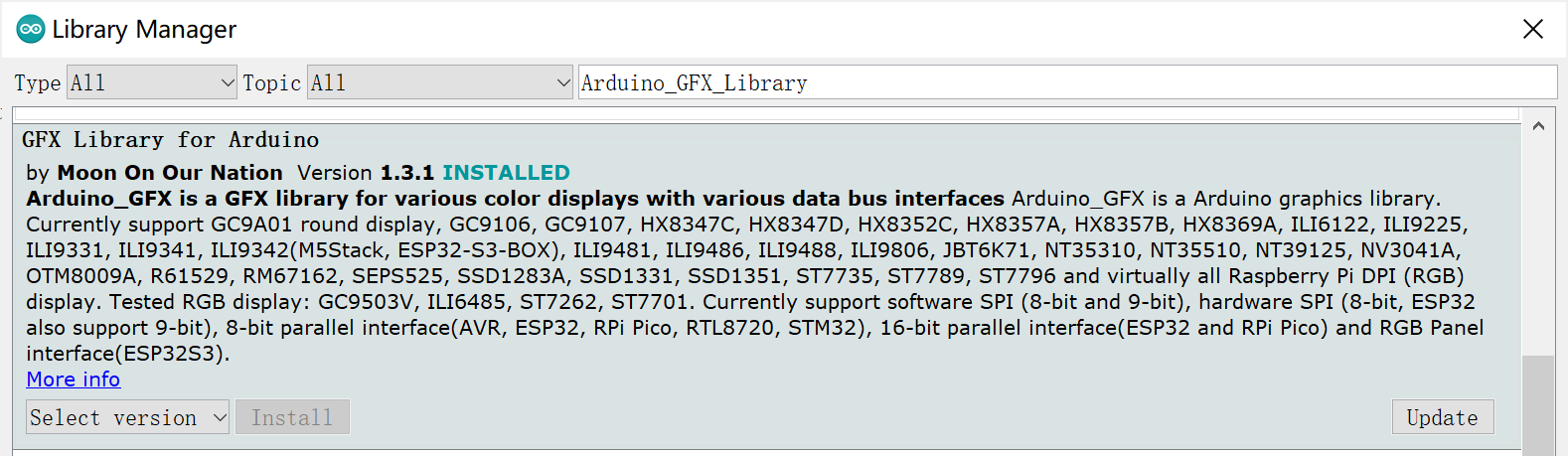
1.Install Arduino_GFX_Library V1.3.1
- Click “Tools> Manager Libraries” to search for and install Arduino_GFX_Library.
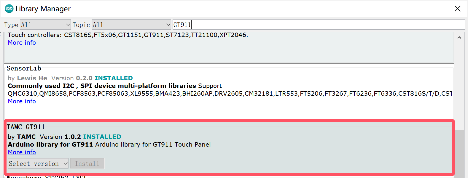
2.Install TAMC_GT911 V1.0.2
- Click “Tools> Manager Libraries” to search for and install TAMC_GT911.
3.1 Display and Touch test
This is a simple demo for displaying and interacting with a touch screen, displaying the touch coordinates (X, Y) on the screen and randomly switching the background colour on each touch.
- Open the display_and_touch_test by Arduino.
Use Type-C USB cable to connect the board and PC, and select the development board "ESP32S3 Dev Module" and the port.
-
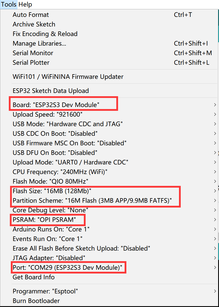
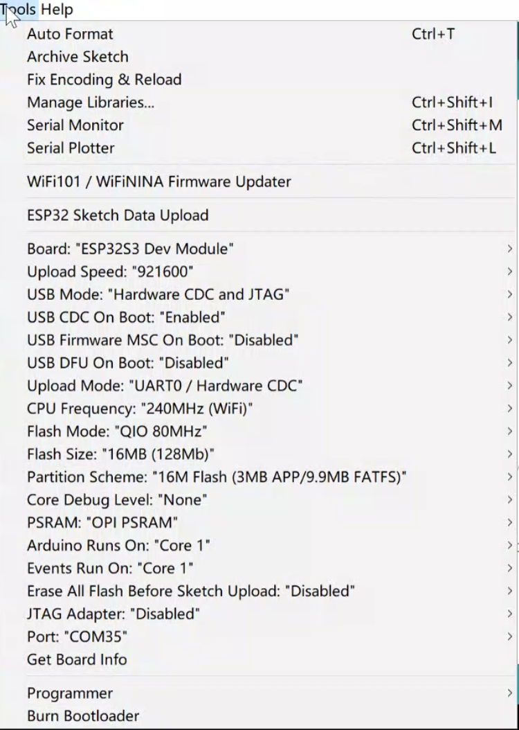
Select "Tools > board:"xxx" > ESP32 Arduino > ESP32S3 Dev Module".
-
Select "Tools > Port",Select the port number of the board.
-
Select Flash Size is 16MB(128MB), Partition Scheme is 16M Flash (3MB APP/9.9MB FATFS), PSRAM is OPI PSRAM.
- Click the Upload button in the Arduino IDE and wait for the code to upload.
Results
3.2 SD test
This demo implements the ability to switch images by touch.
1.Download the SD card file from github and save it to the SD card.
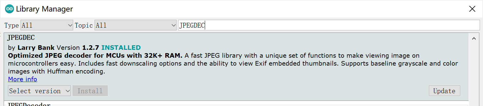
2.Install JPEGDEC V1.2.7
- Click “Tools> Manager Libraries” to search for and install JPEGDEC.
- Open the SD_demo by Arduino.
Use Type-C USB cable to connect the board and PC, and select the development board "ESP32S3 Dev Module" and the port.
-
Select "Tools > board:"xxx" > ESP32 Arduino > ESP32S3 Dev Module".
-
Select "Tools > Port",Select the port number of the board.
-
Select PSRAM is OPI PSRAM.
-
Click the Upload button in the Arduino IDE and wait for the code to upload.
Results
3.3 LovyanGFX demo
This demo uses lovyanGFX library to implement the screen display and touch functions.
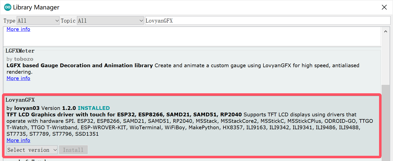
Install LovyanGFX V1.2.0
- Click “Tools> Manager Libraries” to search for and install LovyanGFX.
- Open the LovyanGFX_demo by Arduino.
Use Type-C USB cable to connect the board and PC, and select the development board "ESP32S3 Dev Module" and the port.
-
Select "Tools > board:"xxx" > ESP32 Arduino > ESP32S3 Dev Module".
-
Select "Tools > Port",Select the port number of the board.
-
Select PSRAM is OPI PSRAM.
-
Click the Upload button in the Arduino IDE and wait for the code to upload.
Results
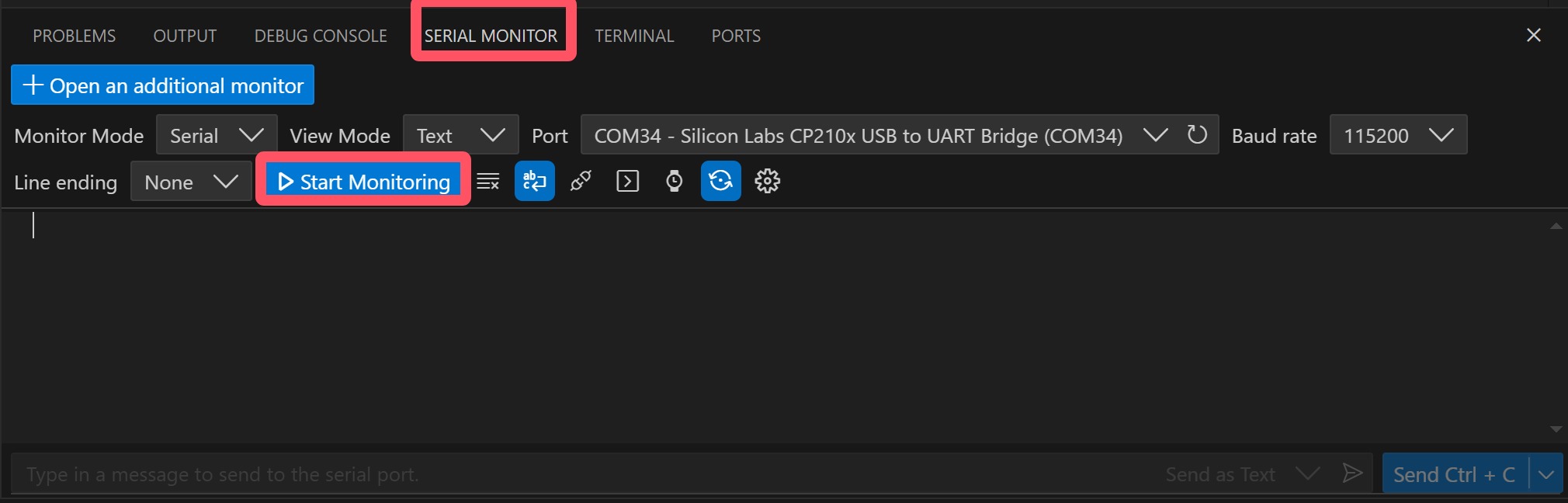
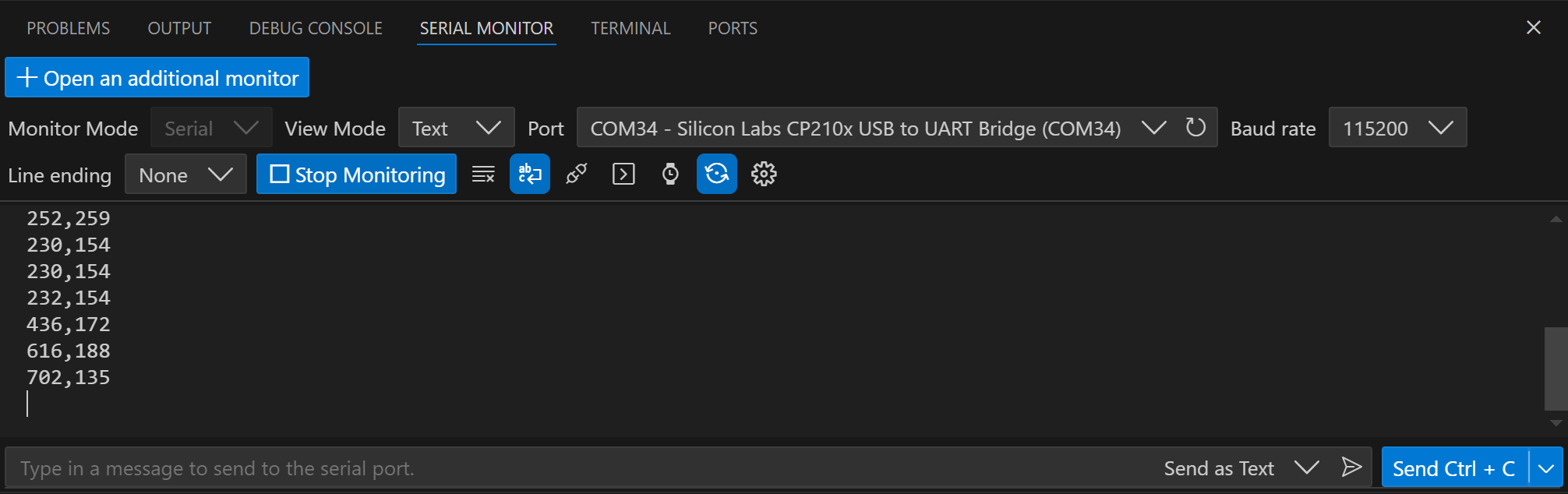
Open the serial monitor and you will be able to see the coordinates of your finger touches.
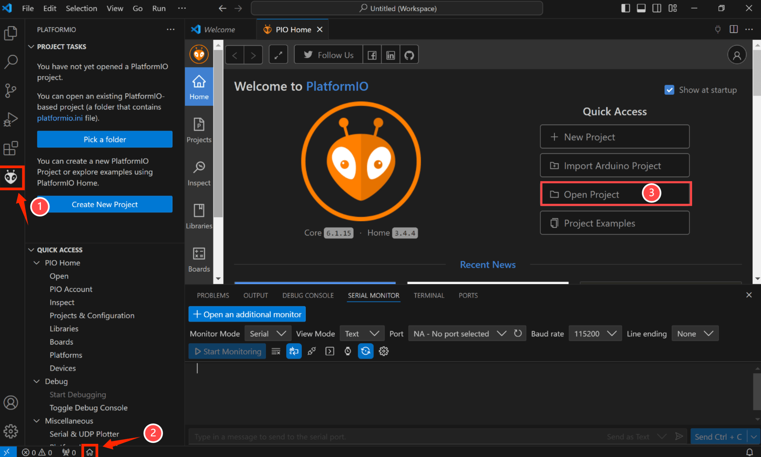
4. Usage in VS Code & PlatformIO
Downloaded and installed PlatformIO IDE for VSCode.
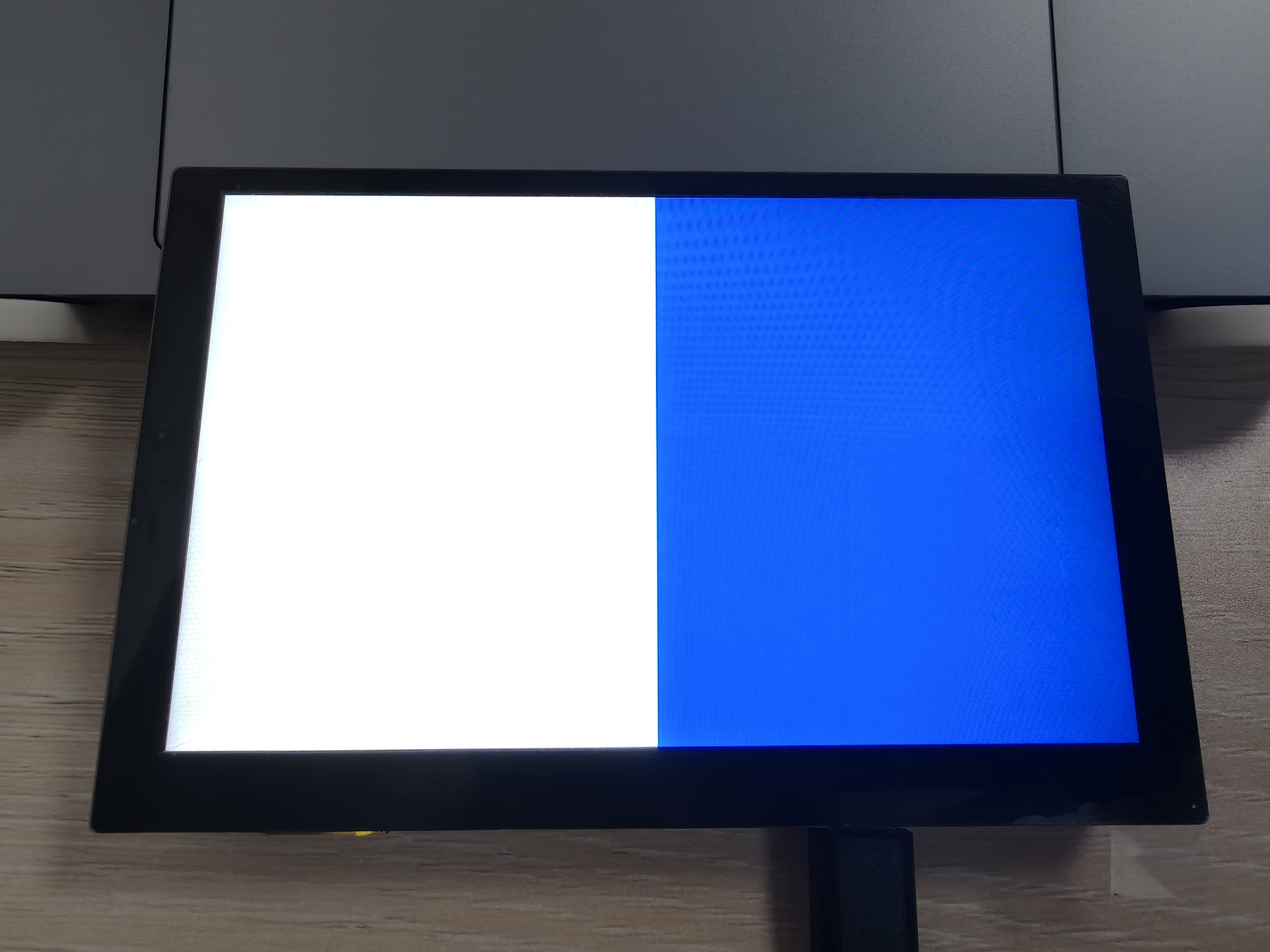
4.1 Display and Touch test
This is a simple demo for displaying and interacting with a touch screen, displaying the touch coordinates (X, Y) on the screen and randomly switching the background colour on each touch.
Download and unzip the Display and Touch test, open this project by VS Code.
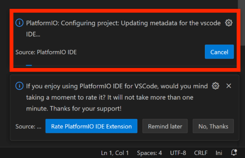
Waiting for configuration project.
- Click "src-->main.cpp".
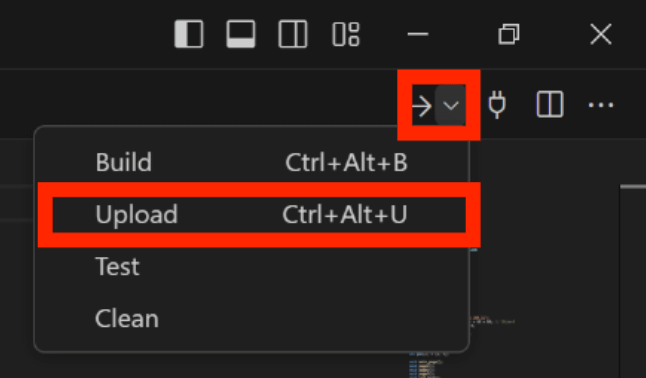
Use Type-C USB cable to connect the board and PC, Click the Upload and wait for the code to upload.
Result:
4.2 SD test
This demo implements the ability to switch images by touch.
Download the SD card file from github and save it to the SD card.
Download and unzip the SD_demo, open this project by VS Code.
Waiting for configuration project.
- Click "src-->main.cpp".
Use Type-C USB cable to connect the board and PC, Click the Upload and wait for the code to upload.
Result:
4.3 LovyanGFX demo
This demo uses lovyanGFX library to implement the screen display and touch functions.
Download and unzip the LovyanGFX_demo, open this project by VS Code.
Waiting for configuration project.
- Click "src-->main.cpp".
Use Type-C USB cable to connect the board and PC, Click the Upload and wait for the code to upload.
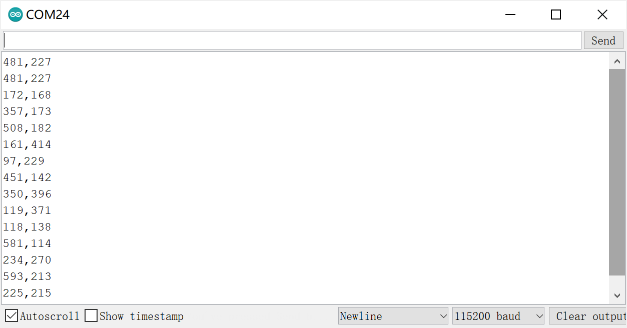
Result:
Open the serial monitor and you will be able to see the coordinates of your finger touches.
5.Usage in Squareline Studio
If you have not installed SquareLine Studio, please follow this guide to install.
Squareline currently only supports 4", 1.9", 2.1" screens, if you want to use other screens, you need to follow this guide to add the relevant simplified packages.
5.1 LVGL design with SquareLine Studio
1.Click on Squareline to log in to your account, or click on "Sign up" if you don't have one.
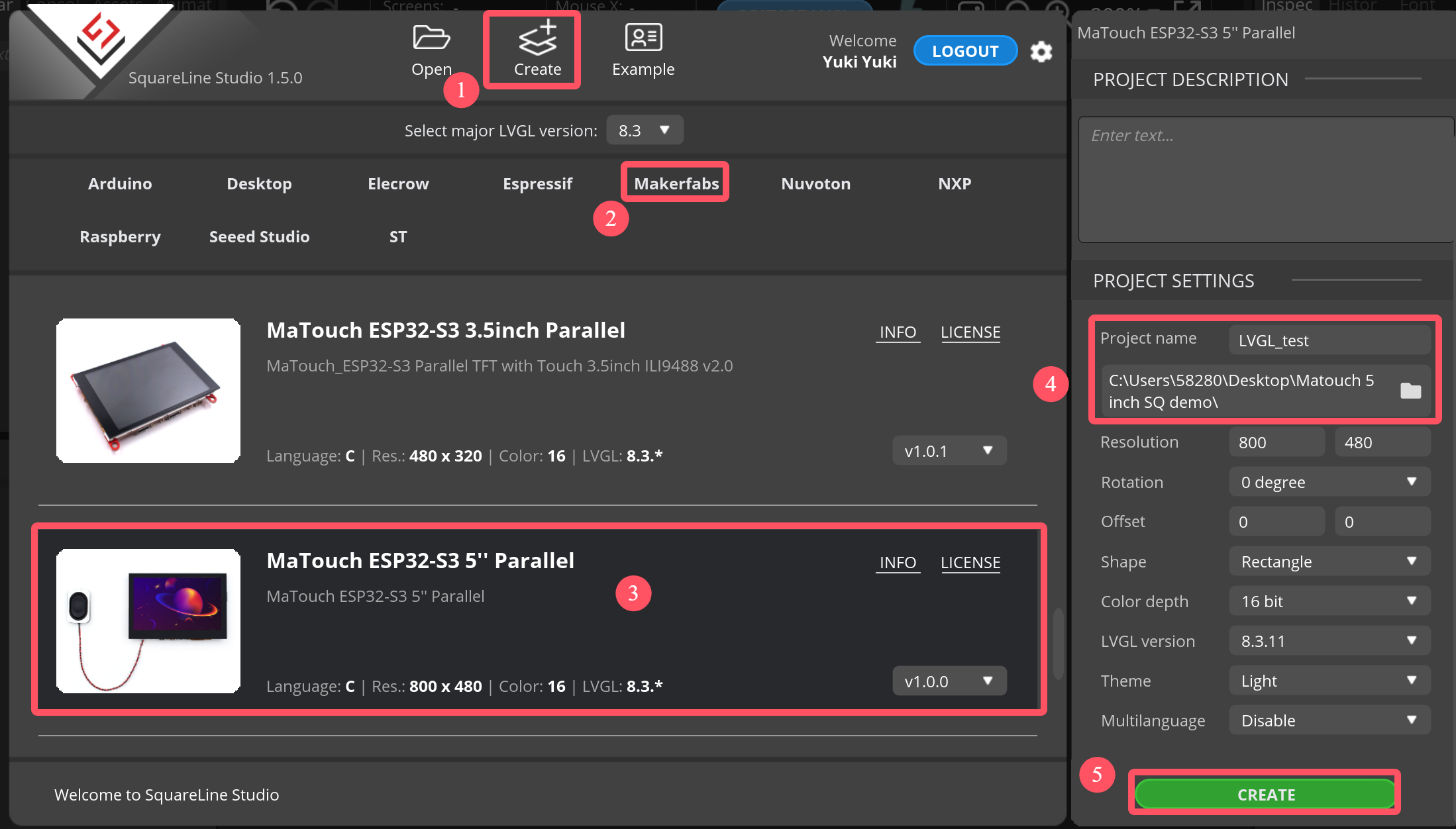
2.Create a project.
-
Click “Crearte-->Makerfabs”.
-
Select “MaTouch ESP32-S3 5” Parallel"
-
modify the desired project name and location information.
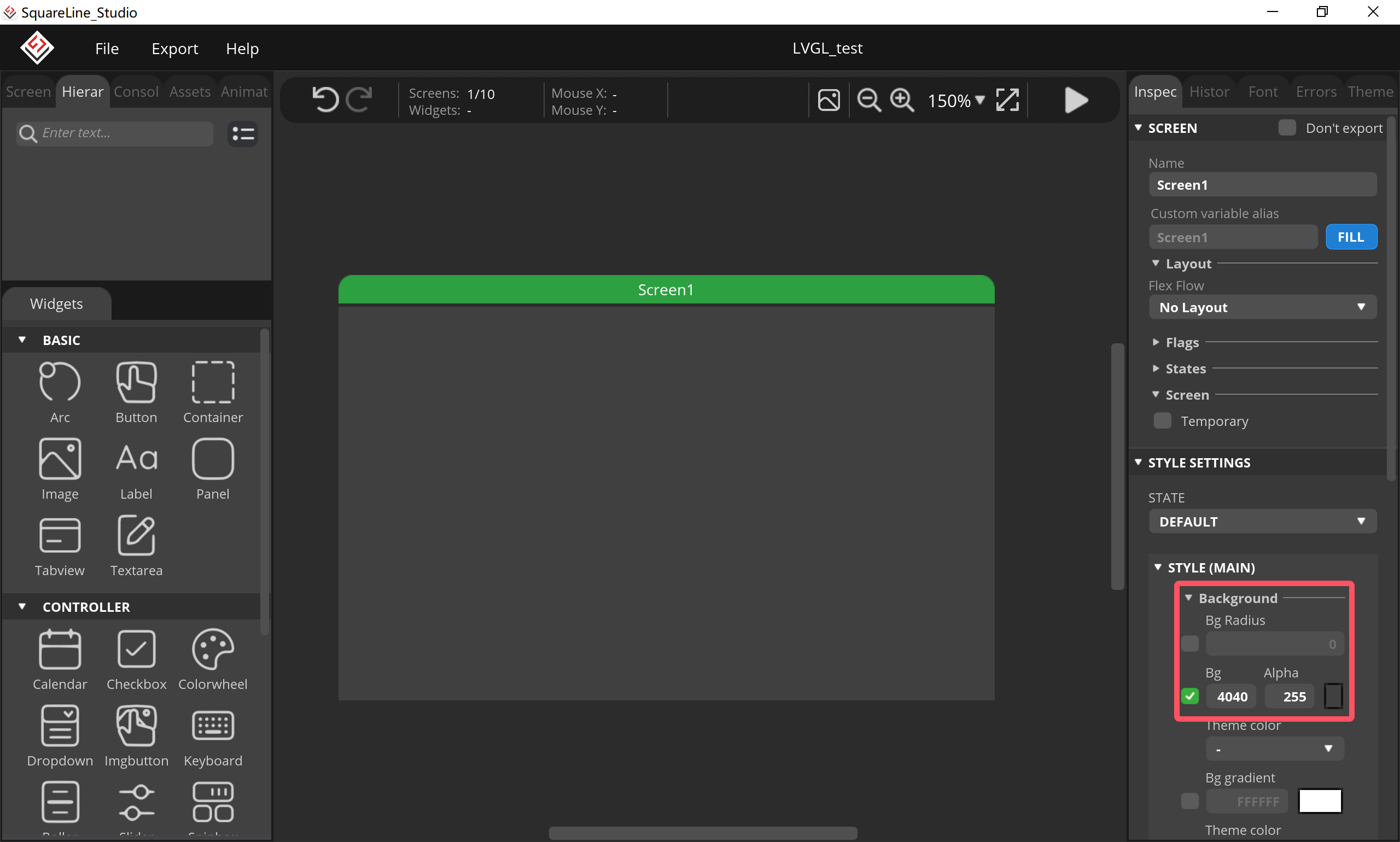
3.Change your favorite background color.
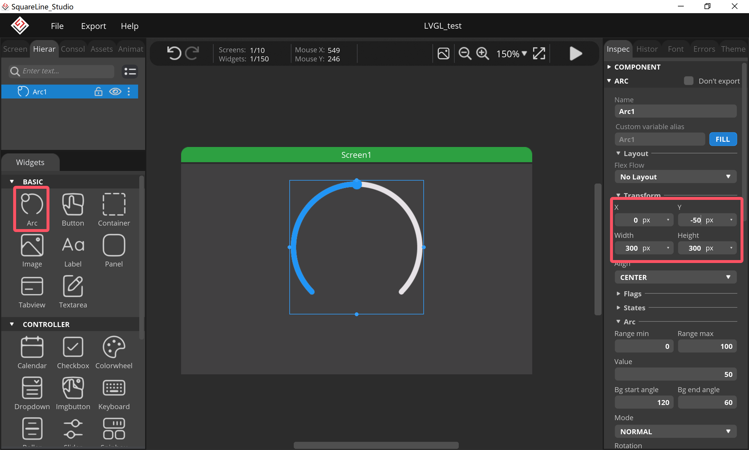
4.Add an arc.
- Click “Arc”, and set its size and position.
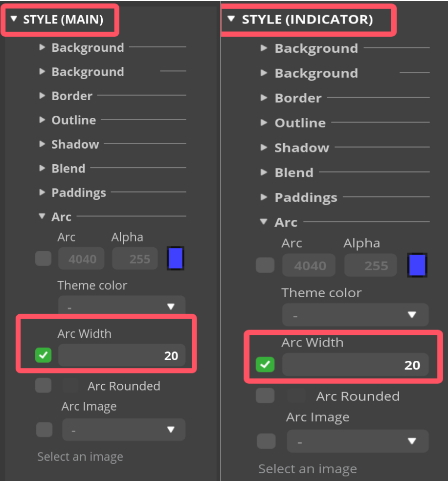
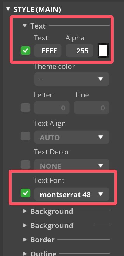
- Set it style.
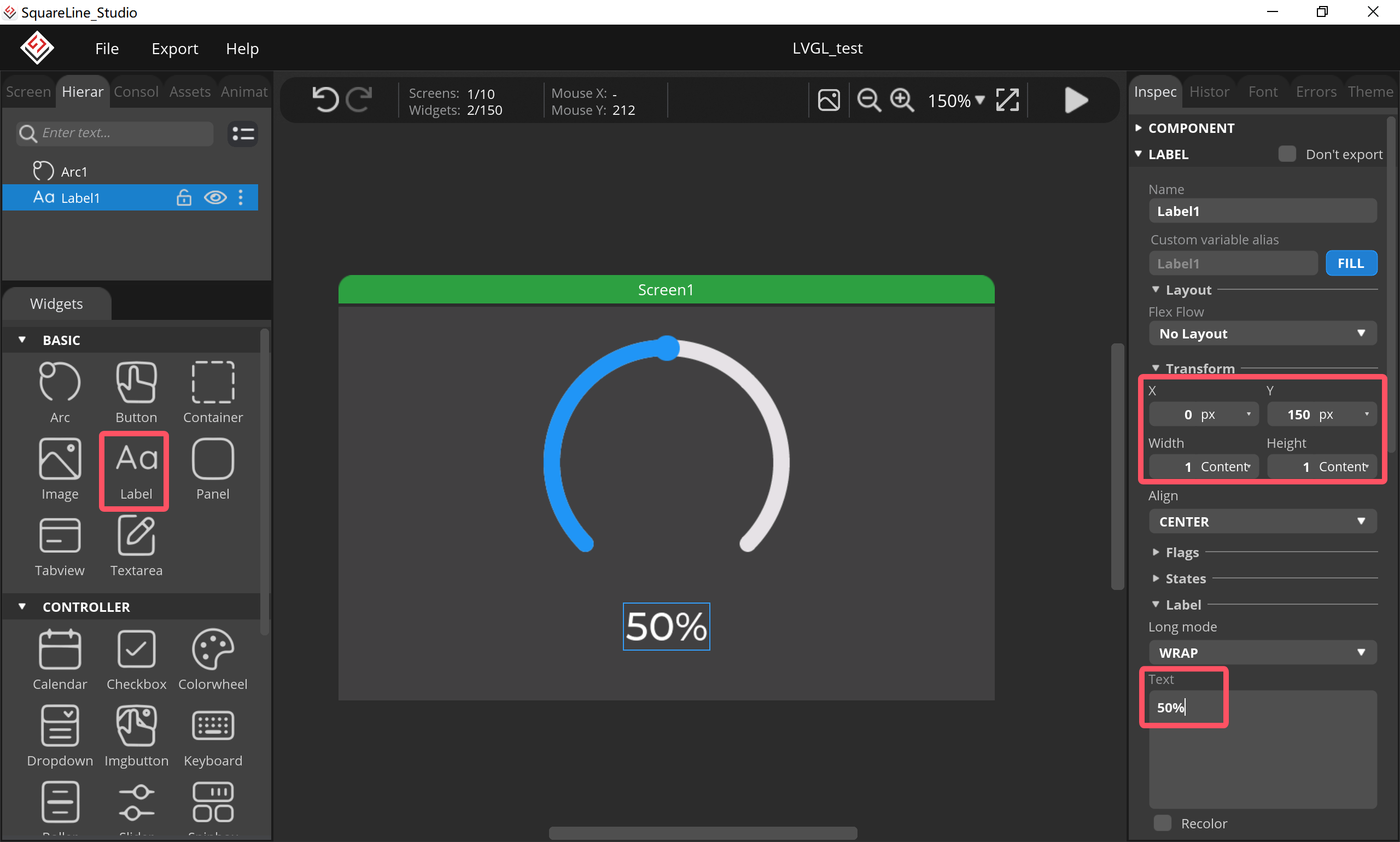
5.Add a label
- Click “Label”, and set its size, position and value.
- Set it style.
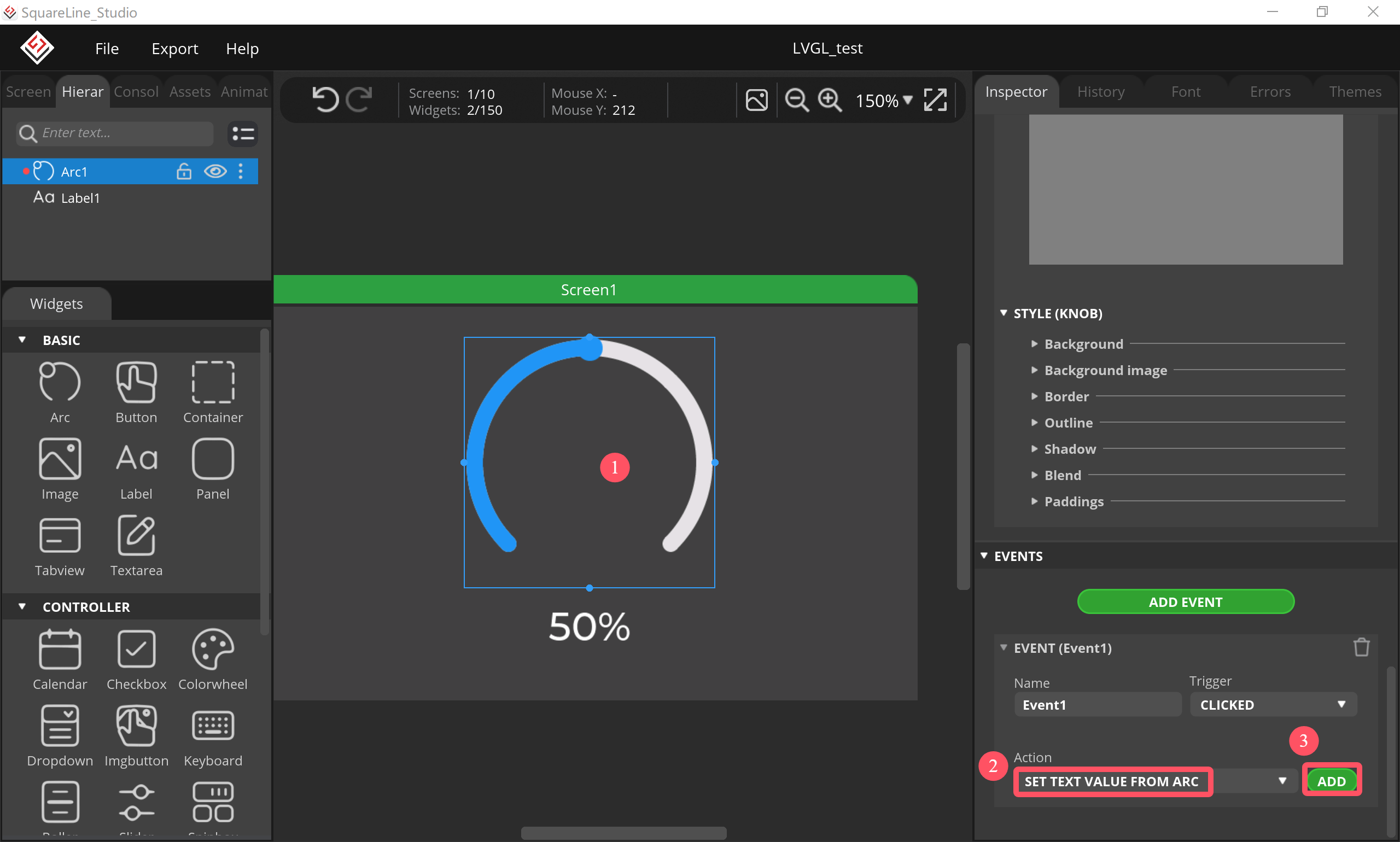
6.Add an event
- Click “Arc”, select “SET TEXT VALUE FOEM ARC” and click “ADD”.
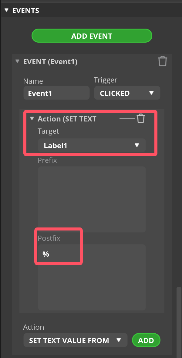
- Set the event, select "Label1".
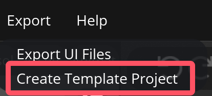
7.Export project.
- Click “Export-->Create Template Project”.
- Export the project file to the location you want.
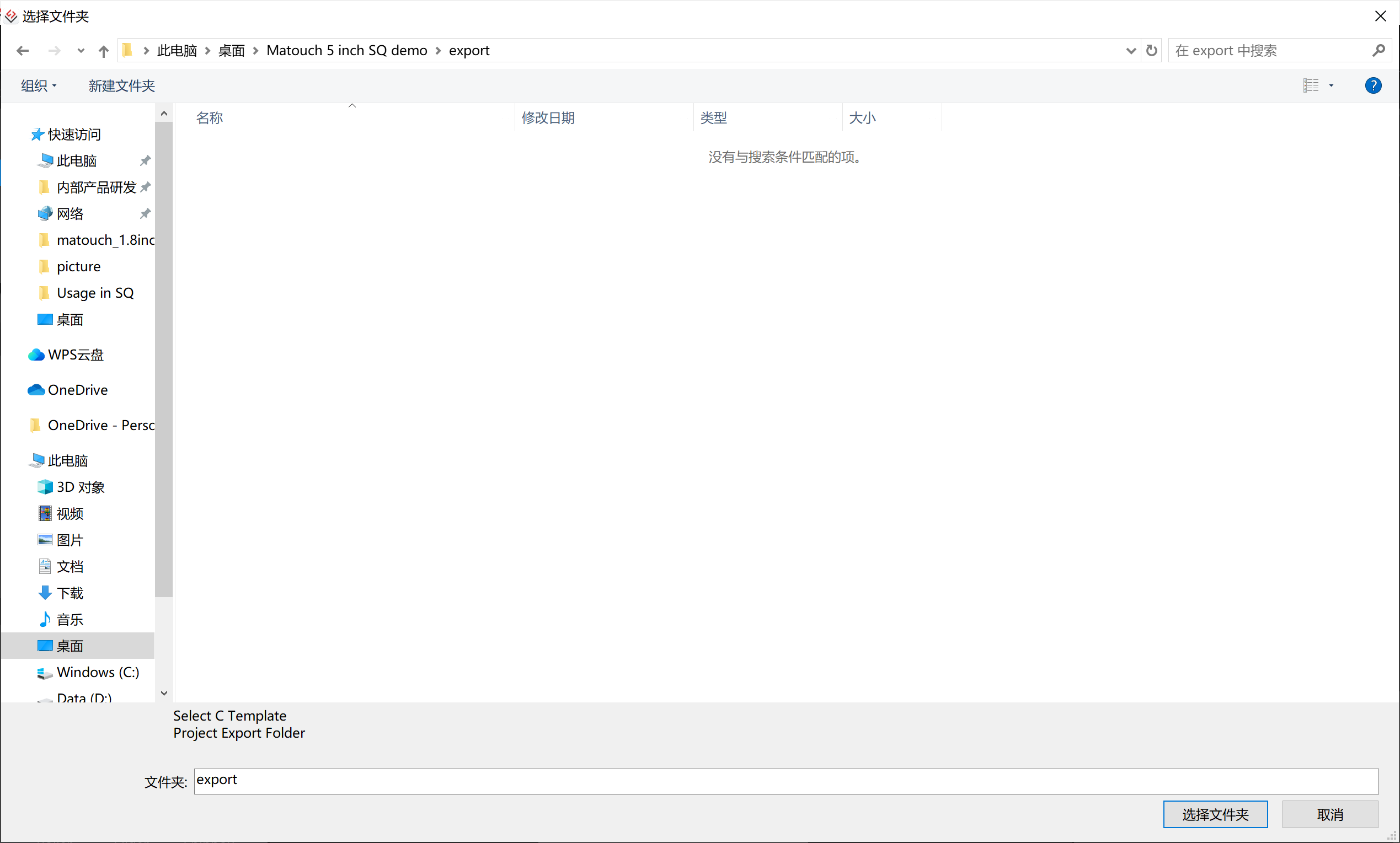
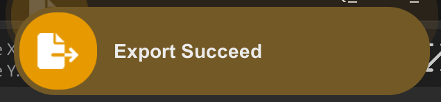
- Wait for export succeed.
5.2 Code Upload with Arduino IDE
This projects are based on ESP32-S3 development board. If you didn't install the ESP32 Board SDK, you can follow this guide to learn how to do it.
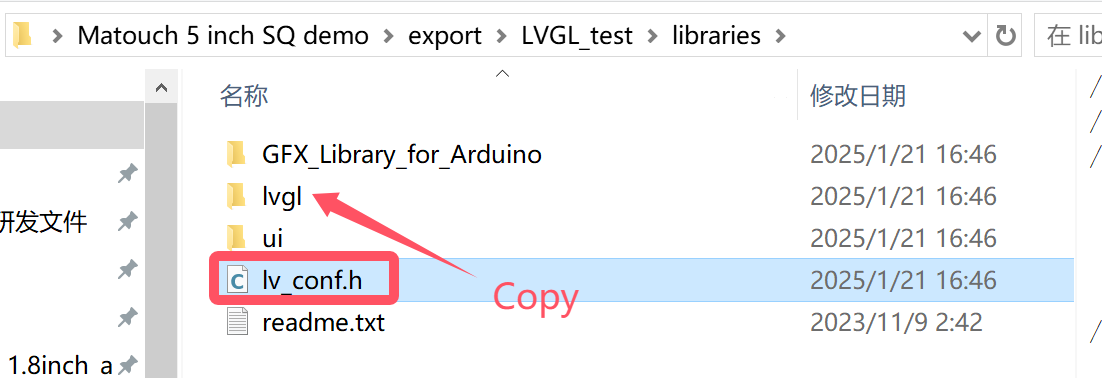
1.Click on the code project document you just export. (Or download code in github)
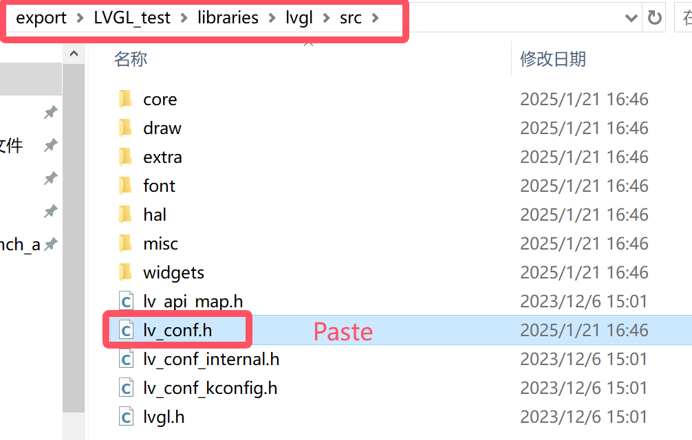
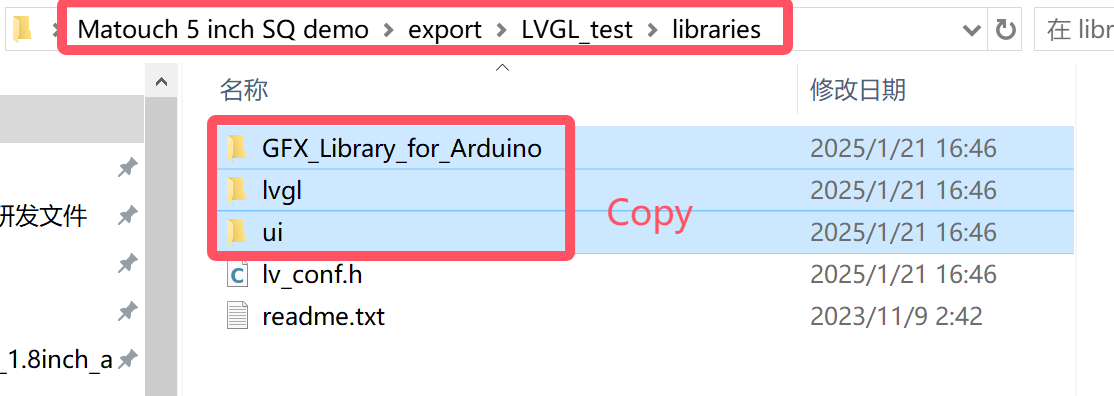
- Copy the “lv_conf.h” into the “src” in the lvgl in libraries.
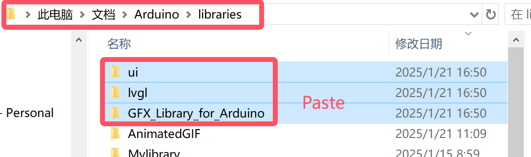
- Copy these files into the Arduino library.
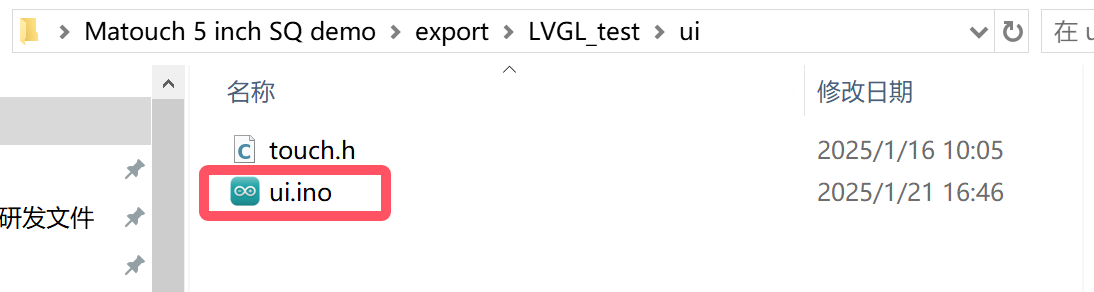
- Open the ui.ino.
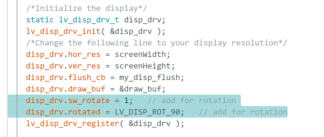
- If you want a vertical display, please add the following two lines to void setup().
disp_drv.sw_rotate = 1;   // add for rotation
disp_drv.rotated = LV_DISP_ROT_90;   // add for rotation
- Before uploading the sketch, select and set the parameter in the Tools menu, as picture:
5.3 Result
6. FAQ
You can list your questions here or contact techsupport@makerfabs.com for technology support. Detailed descriptions of your question will help to solve your question.
Q1: I get the error "no matching function for call to 'Arduino_ESP32RGBPanel::Arduino_ESP32RGBPanel(int, int, int, int, int, int, int, int, int, int, int, int, int, int, int, int, int, int, int, int, int, int, int)'); ^" when I compile the code, how to solve it?

A1: Mabe you use the ArduinoGFX v1.4.9 not the tested v1.3.1. The oringinal code need to make some changes to support v1.4.9 as below:
#if 0  //for Arduino_GFX_Library v1.3.1
Arduino_ESP32RGBPanel *bus = new Arduino_ESP32RGBPanel(
    GFX_NOT_DEFINED /* CS */, GFX_NOT_DEFINED /* SCK */, GFX_NOT_DEFINED /* SDA */,
    40 /* DE */, 41 /* VSYNC */, 39 /* HSYNC */, 42 /* PCLK */,
    45 /* R0 */, 48 /* R1 */, 47 /* R2 */, 21 /* R3 */, 14 /* R4 */,
    5 /* G0 */, 6 /* G1 */, 7 /* G2 */, 15 /* G3 */, 16 /* G4 */, 4 /* G5 */,
    8 /* B0 */, 3 /* B1 */, 46 /* B2 */, 9 /* B3 */, 1 /* B4 */
);

Arduino_RPi_DPI_RGBPanel *gfx = new Arduino_RPi_DPI_RGBPanel(
   bus,
   800 /* width */, 0 /* hsync_polarity */, 8 /* hsync_front_porch */, 4 /* hsync_pulse_width */, 8 /* hsync_back_porch */,
   480 /* height */, 0 /* vsync_polarity */, 8 /* vsync_front_porch */, 4 /* vsync_pulse_width */, 8 /* vsync_back_porch */,
   1 /* pclk_active_neg */, 16000000 /* prefer_speed */, true /* auto_flush */);
#endif  //end of  for Arduino_GFX_Library v1.3.1

#if 1  //for Arduino_GFX_Library v1.3.7 or v1.4.9
Arduino_ESP32RGBPanel *rgbpanel = new Arduino_ESP32RGBPanel(
    40 /* DE */, 41 /* VSYNC */, 39 /* HSYNC */, 42 /* PCLK */,
    45 /* R0 */, 48 /* R1 */, 47 /* R2 */, 21 /* R3 */, 14 /* R4 */,
    5 /* G0 */, 6 /* G1 */, 7 /* G2 */, 15 /* G3 */, 16 /* G4 */, 4 /* G5 */,
    8 /* B0 */, 3 /* B1 */, 46 /* B2 */, 9 /* B3 */, 1 /* B4 */,
    0 /* hsync_polarity */, 8 /* hsync_front_porch */, 4 /* hsync_pulse_width */, 8 /* hsync_back_porch */,
    0 /* vsync_polarity */, 8 /* vsync_front_porch */, 4 /* vsync_pulse_width */, 8 /* vsync_back_porch */,
    1 /* pclk_active_neg */, 16000000 /* prefer_speed */);

Arduino_RGB_Display *gfx = new Arduino_RGB_Display(
    800 /* width */, 480 /* height */, rgbpanel, 0 /* rotation */, true /* auto_flush */);
#endif  //end of  for Arduino_GFX_Library v1.3.7 or v1.4.9