Maduino Zero 4G LTE
1. Introduction
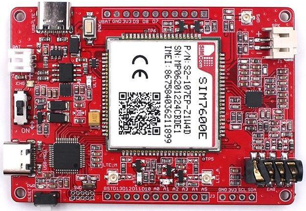
Maduino Zero 4G LTE integrated two types of the 4G LTE CAT4 module SIM7600A-H or SIM7600E-H, SIM7600A-H/SIM7600E-H is a complete multi-band LTE-FDD/LTE-TDD/HSPA+/UMTS/EDGE/GPRS/GSM module solution in LCC type which supports LTE CAT4 up to 150Mbps for downlink and 50Mbps for uplink data transfer, much faster and popular than 2G/3G.
Model:OHMZ4G7600
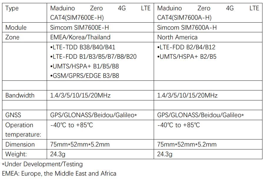
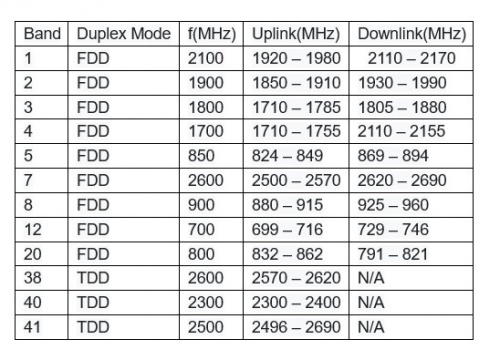
Frequency bands
Data comes from wiki
Here is a referenced LTE band lists List of LTE networks
Please check the supported bands according to your local service provider, select the proper one when placing order.
Specifications for Data transfer
| Uplink | Downlink | |
|---|---|---|
| LTE CAT4 | 50Mbps | 150Mbps |
| HSPA+ | 5.76 Mbps | 42 Mbps |
| UMTS | 384Kbps | 384Kbps |
| EDGE | 236.8Kbps | 236.8Kbps |
| GPRS | 85.6Kbps | 85.6Kbps |
2. Features
- Supports dial-up, phone, SMS, TCP, UDP, DTMF, HTTP, FTP, and so on
- Dual USB Type C port
- Control Via AT Commands
- Board USB supply voltage range: 4.8~5.5V, 5.0V Typical
- Board Battery supply voltage range: 3.4~4.2V, 3.7V Typical
- 3GPP E-UTRA Release 11
- Onboard charger, up to 1A charge current
- Overcharge protection(OCP), 4.3V
- Over-discharge protection(ODP), 2.5V
- Power Manager, the board can be supplied by USB or battery.
- IPEX Antenna, GSM/UMTS/LTE main antenna. UMTS/LTE auxiliary antenna. GNSS antenna
- SMS support
- Audio support
- On boarder controller: ATSAMD21G18A
- Audio Codec: NAU8810
- Level Shifter: TXS0108E
- Windows and Raspberry Pi support
- Qualcomm MDM9x07 Chipset
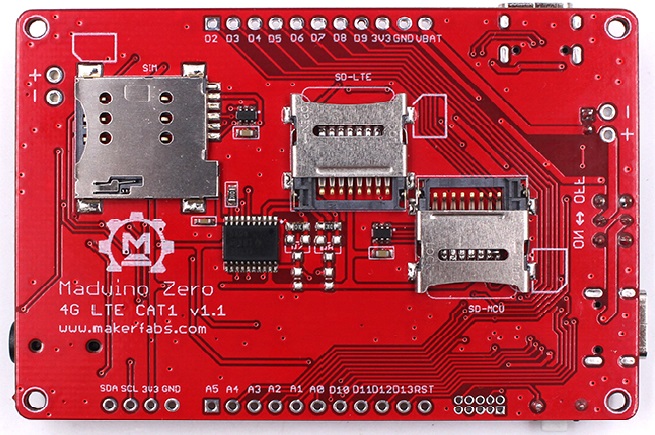
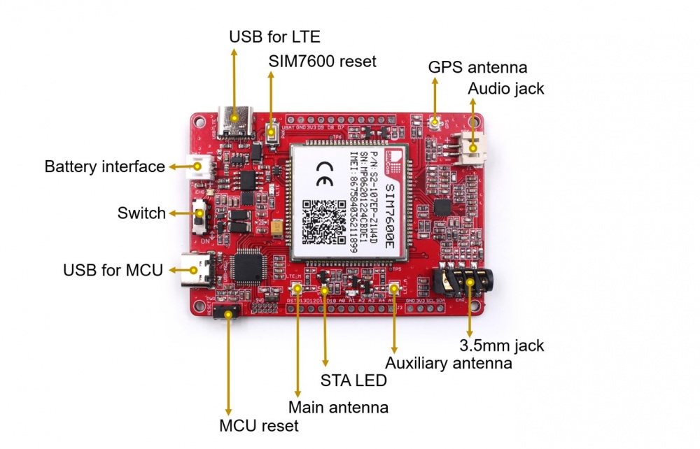
3. Interface
4. Usage
Warning:Do not operate when in power on (don’t plug or unplug the Antenna, SIM Cars, SD Card, in case of short-circuiting that may burn the IC down.)
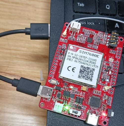
4.1 Hardware connecttion
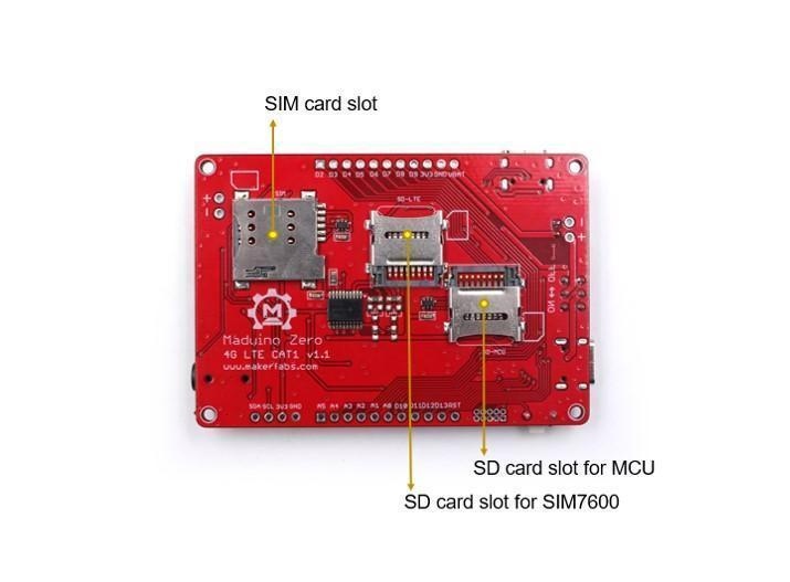
1.Plug the SIM card into the board.
2.Plug the GPS antenna into the interface.
3.Plug two 4G-GSM antennas into the main antenna interface and auxiliary one.
4.Plug the headphone with the microphone.
5.Plug the SD card into the SD card slot for SIM7600.
When powering the board and the SIM7600 module working, the onboard STA LED(blue) will turn on.
4.2 How to use AT commands
For using AT commands by the serial communication, it needs to upload the sketch to this board. The source code is available on GitHub.
- Note that there are few AT-Commands may not return the accurate values as the manual says for the different version of the SIM7600
1.Open the sketch by Arduino IDE.
2.Use Type-C USB cable to connect the board and PC, note plug the cable into the USB-MCU interface.
3.Select "Tool --> Board --> Arduino Zero" and the port.
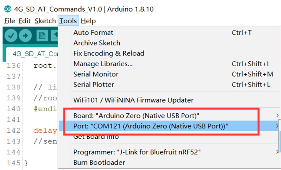
4.Verify the code and upload.
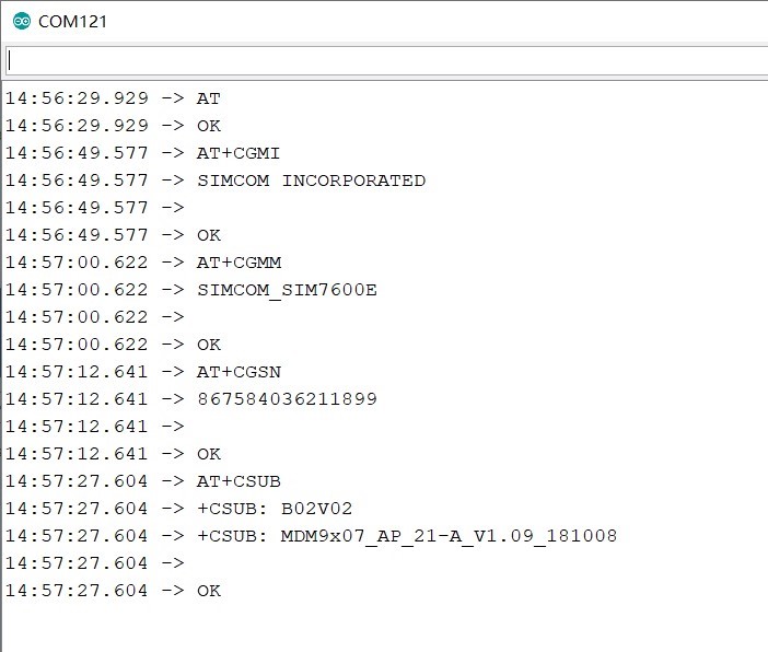
5.Open the serial monitor, select the "Both NL&CR"and send the AT command to the board, and it will return the module's response.
6.There are some demos that show how to use the AT commands:
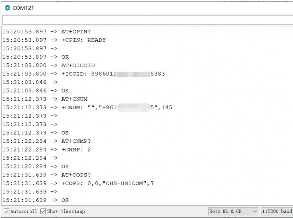
- AT commands test
    AT+CGMI    // Request manufacturer identification
    AT+CGSN    // Request product serial number identification
    AT+CSUB    // Request the module version and chip
    AT+SIMCOMATI //Request a total info of the module
    AT+CPIN?     // Request the state of the SIM card
    AT+CICCID    // Read ICCID from SIM card
    AT+CNUM      // Request the subscriber number
    AT+CNMP?     // Preferred mode selection
    AT+COPS?     // Check the current network operator
    AT+IPREX?    // Check local baud rate
    AT+CRESET    // Reset the module
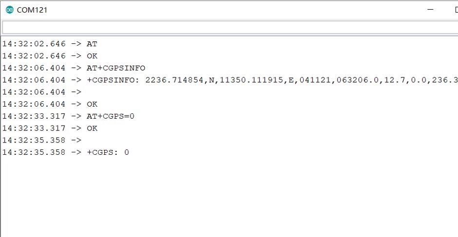
- Get the GNSS location
    AT+CGPS=1      // Start GPS session
    AT+CGPSINFO    // Get GPS fixed position information
    AT+CGPS=0      // Stop GPS session
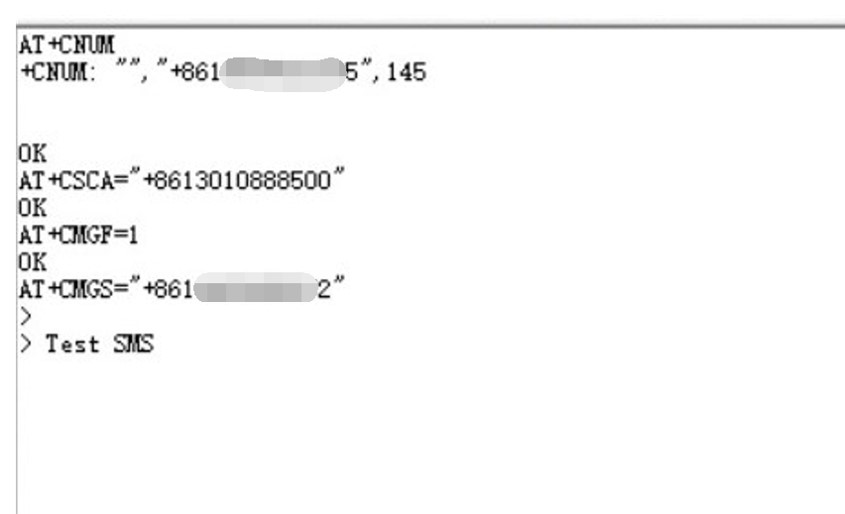
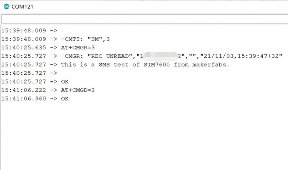
- Send and receive SMS
Note that is recommended to use other serial monitors not the Arduino IDE one to send the AT command for this demo.
    AT+CSCA="XXXXXX"       // Set the SMS service centre address(it isn't your SIM number)
    AT+CMGF=1              // Select SMS message format
    AT+CMGS="xxxxxx"       // Send message to "xxxxxx"(the receiver number).
After sending the above AT commands, it will show ">" and then you can send your message. When you finish your message, you need to send "1A" with hexadecimal for confirmation or send "1B" with hexadecimal for cancellation, that is why recommended to use other serial monitors.
    AT+CMGR=3        // Read message
    AT+CMGD=3        // Delete message
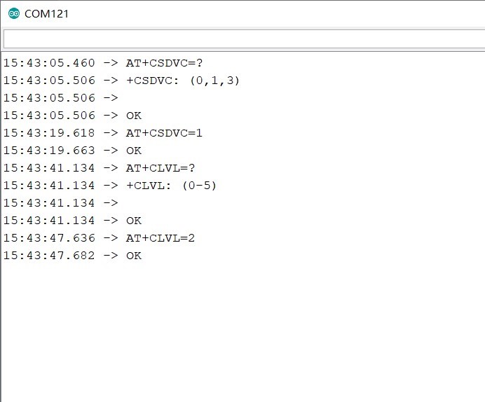
- Make a call
    AT+CSDVC         // Switch voice channel device
    AT+CSDVC=1       // 1-Handset, 3-Speaker phone
    AT+CLVL=2        // Set loudspeaker volume level to 2, the level range is 0 to 5
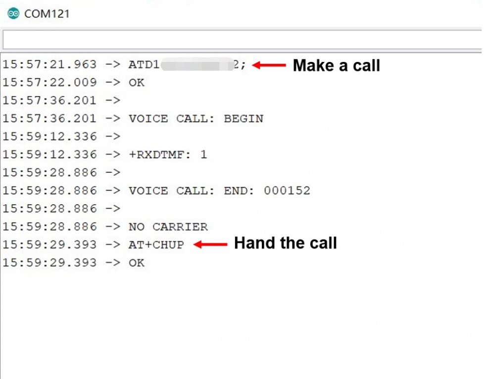
ATDxxxxx; // Call to xxxxx
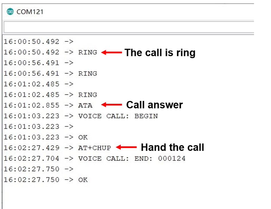
AT+CHUP // Hang up the call
    AT+CLIP=1     // Calling line identification presentation
    ATA         // Call answer
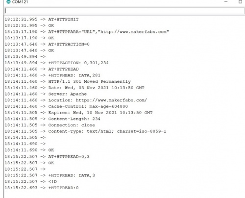
- HTTP test
    AT+HTTPINIT         // Initialize and start the HTTP
    AT+HTTPPARA="URL","http://www.makerfabs.com"  // Set the URL
    AT+HTTPACTION=0    // Connect the HTTP. (0-get, 1-post, 2-head)
    AT+HTTPHEAD        // Read the response's header.
    AT+HTTPREAD=0,3    // Read the content (“3” means the number of the reading data)
- Test the SD card for SIM7600
When you plug an SD card into the SD card slot for SIM7600, You can use the following commands to check it.
    AT+FSCD=D:                    // Select SD card directory as current directory
    AT+FSLS                       // List directories/files in current directory
    AT+CFTRANRX="D:/TEST.txt",9  // Transfer a file to EFS, input 9 letters after returns ">" ,such as Makerfabs
    AT+CFTRANTX="D:/TEST.txt"     // Transfer a file from EFS to host
- More AT commands detail please check SIM7500_SIM7600_Series_AT_Command_Manual_V1.10.pdf
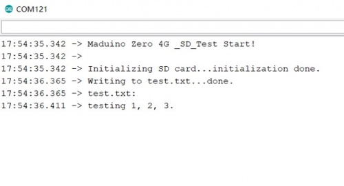
4.3 Test microSD card of MCU
When you have plugged the microSD card into the microSD card slot of MCU, it can not use the AT commands to read or write. There is a demo shows how to read and write the microSD card for MCU.
- It is required to upload a sketch to the board. The source code is available on GitHub.
- Open the sketch by Arduino IDE.
- Use Type-C USB cable to connect the board and PC, note plug the cable to USB-MCU interface.
- Select "Tool --> Board --> Arduino Zero" and the port.
- Verify the code and upload.
- Open the serial monitor, it will print the message of the SD writing and reading.
4.4 Surfing the internet
Maduino Zero 4G LTE can be a wireless networking device to support the PC or Raspberry PI surfing the internet. Next, it will show how to do it.
-
It needs to install the SIM7600 driver to the PC, the driver is available on resources
-
Use Type-C USB cable to connect the board(USB-LTE) and PC, note plug the cable into the USB of MCU.
- Download the driver to the PC.
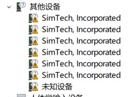
- Follow the below step to install the driver manually:
1.Open "Device Manager".
2.In "Device Manager", select "Other devices".
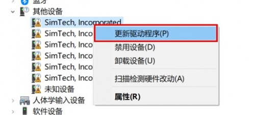
3.Right-click on and click "Update Driver Software".
4.Select "Browse my computer for driver software".
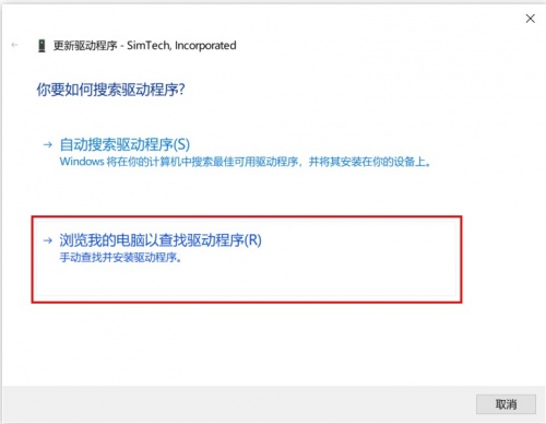
5.Paste the location address of the driver into the location field, then click "Next".
6.Wait until the drivers' installation process completes.
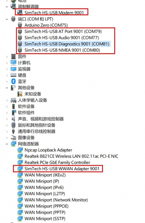
Note: Install all the drivers that shows as yellow exclamation mark. - If the PC does not connect to the internet through this device, please open the serial monitor and send the AT command to start the networking.
AT$QCRMCALL=1,1
If have not yet, please use the PPP dial-up connection way to start networking.
More info you can get from GitHub
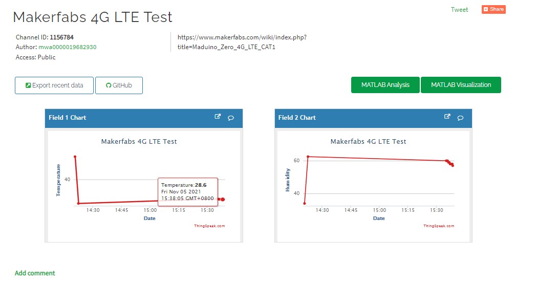
4.5 Transmit T&H to Thingspeak
This demo will show you use this device to transmit the temperature and humidity to Thingspeak that the T&H CAN be checked everywhere.
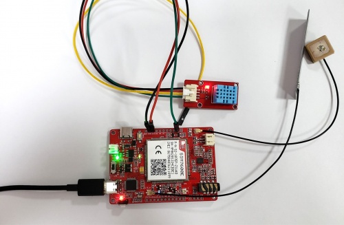
- Prepare a DHT11 module for detecting the temperature and humidity.
- Follow the wiring to connect the DHT11 module and the board.
| DHT11 | Maduino Zero 4G LTE |
|---|---|
| VCC | 3V3 |
| GND | GND |
| DATA | D3 |
- The sketch for this demo is available on Github.
- To transmit the data to your Thingspeak channel, it has to create a new channel and get the APIKEY information. Then replace the APIKEY in the code with yours.

- Open the sketch by Arduino IDE.
- After connecting the antenna and SIM card, plug the cable into the USB-MCU interface and connect - with the PC.
- Select "Tool --> Board --> Arduino Zero" and the port.
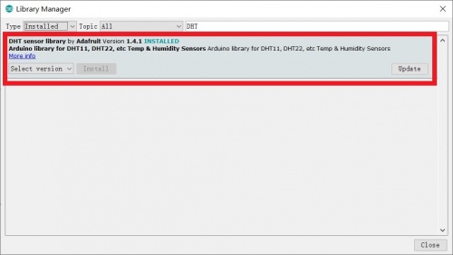
- Install the library for DHT11 module.
- Upload the sketch to the board.
- The device will transmit the data to the internet every 5 seconds, you can check the temperature and humidity on the Thingspeak channel.
4.6 Using it with Raspberry Pi
Also, Maduino Zero 4G LTE can be used with Raspberry Pi
4.7 Some information
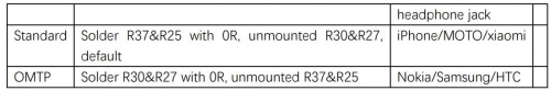
There are two types of the 3.5mm headphone jack. Maduino Zero 4G LTE support the standard type.
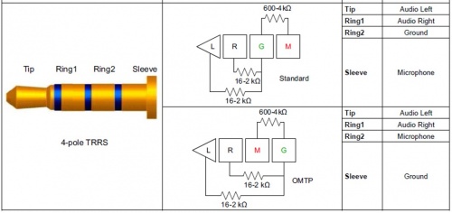
Some changes need to be made if your headphone is not the standard type.
5. FAQ
You can list your question here or contact techsupport@makerfabs.com for technology support. Detailed descriptions of your question will be helped to solve your question.
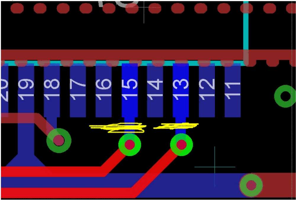
Q:When using 3.3V pull-up resistors, the input values of D8 are sometimes low and sometimes high, are there some problems with it ?
A:when you turn on the SIM7600 module ,D8 and D9 from the SAMD are connected to RI and DTR on the SIM7600 through level shifter TXS1080E, as part of the UART interface. when receiving SMS, or a URC report is coming, the DTR pin can be used to wake module from sleep and RI ,for getting the low level . If you don't need DTR and RI function, you can cut out the wires with a knife,as show in the image.
Q:Can D8 and D9 be used as general purpose IO ? A:D8 and D9 can be used as general purpose IO if it not connect to SIM7600 via TXS0108E.