ESP32-S3 Parallel 4.3" TFT with Touch
Introduction
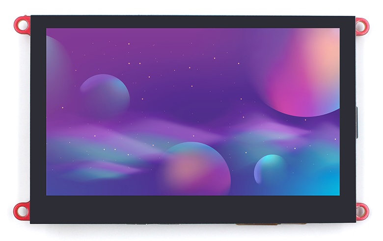
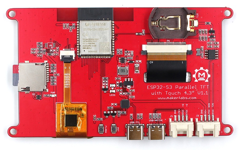
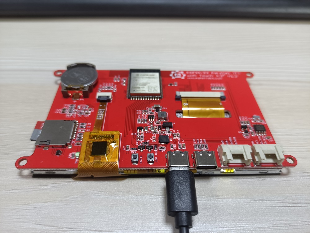
This ESP32 4.3 inch IPS display could be an ideal displayer& controller for IoT applications. Its high lightness IPS display with a resolution of 800*480 makes the display effect beautiful, together with 5 points capacitive touch, great for applications such as home automation; There onboard SD card and RTC, to make it possible to record/play filed data. Also, there 2 Mabee/ Grove connectors, so the users can connect kinds of sensors to this board, to create personal prototype projects instantly.
The ESP32-S3 has WiFi& Bluetooth 5.0, and 8M PSRAM ESP32-S3 is used in this product, with 16M FLASH, to make it competent for more advanced applications.
Model:E32S3RGB43
Features
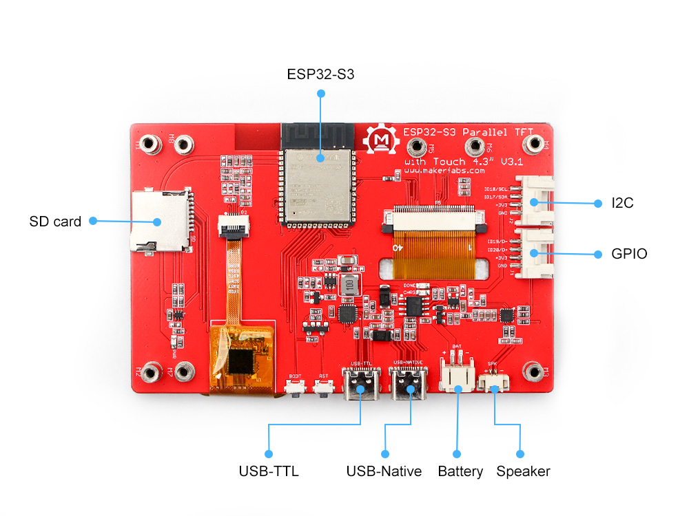
- Controller: ESP32-S3-WROOM-1, PCB Antenna, 16MB Flash, 8MB PSRAM, ESP32-S3-WROOM-1-N16R8
- On Board RTC
- Wireless: Wifi& Bluetooth 5.0
- LCD: 4.3 inch High Lightness IPS
- FPS: >30
- Resolution: 800*480
- LCD interface: RGB 565
- Touch Panel: 5 Points Touch, Capacitive
- Touch Panel Driver: GT911
- USB: Dual USB Type-C(one for USB-to-UART and one for native USB)
- USB to UART Chip: CP2104
- Power Supply: USB Type-C 5.0V(4.0V~5.25V)
- Button: Flash button and reset button
- Mabee interface: 1I2C;1GPIO
- MicroSD: Yes
- Type-C Power Delivery: Not Supported
- Operation temperature: -40℃ to +85℃
- Screen outline: 105.50x67.20x3.0(mm)
Usage
To ensure the running environment, the same version is recommended.
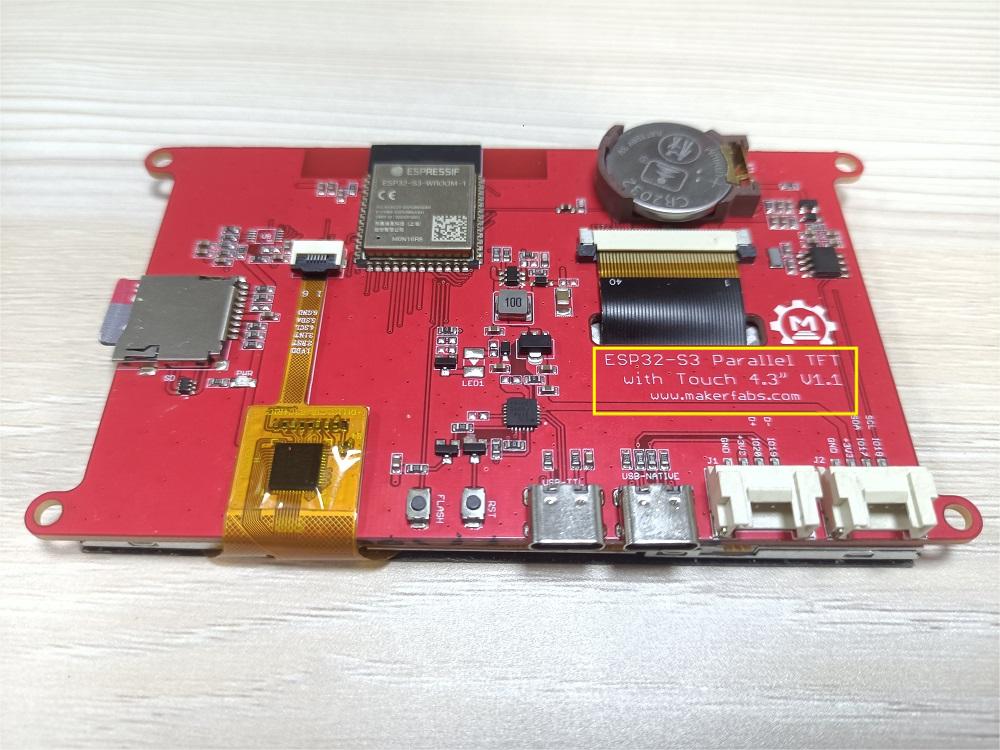
Note: When users use the ESP32-S3 Parallel 4.3 TFT with Touch, please check the version of the board.
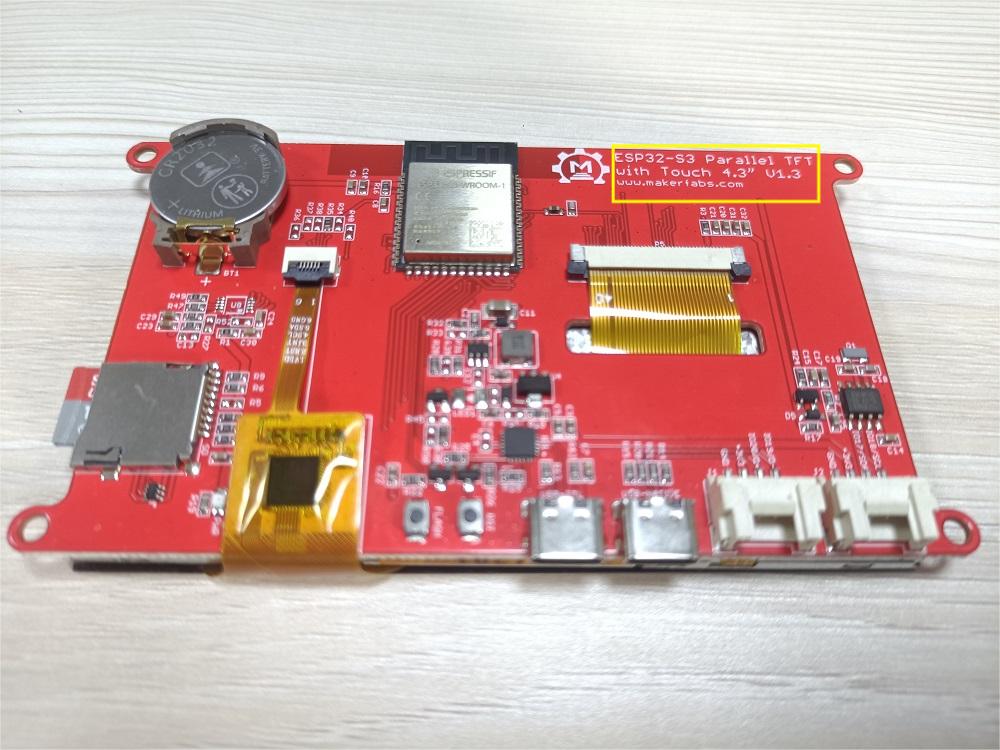
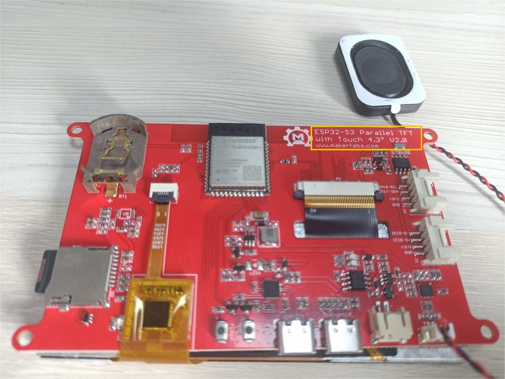
-
If the version of ESP32-S3 Parallel 4.3 TFT with Touch is v1.1. These documentations are put up on GitHub of V1.1.
-
If the version of ESP32-S3 Parallel 4.3 TFT with Touch is v1.3. These documentations are put up on GitHub of V1.3.
-
If the version of ESP32-S3 Parallel 4.3 TFT with Touch is v2.0. These documentations are put up on GitHub of V2.0.
In 2.0 and later versions, if you need backlight control, you need to solder R59 (the default is not soldered when leaving the factory), and if the screen will flicker after soldering, you can remove the R29 resistor.
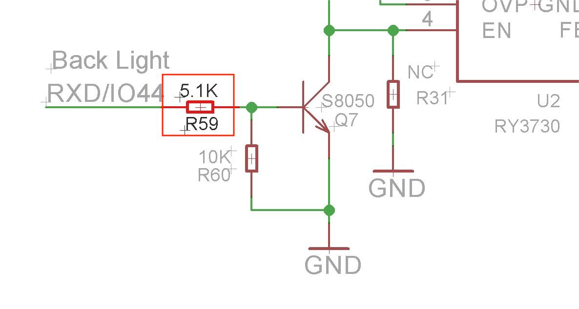
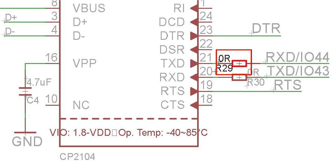
The version number is on the back of the ESP32-S3 Parallel 4.3 TFT with Touch.
All the projects are based on ESP32-S3 development board. If you didn't install the ESP32 Board SDK, you can follow this guide to learn how to do it.
Installed the "TAMC_GT911 V1.0.2" in the Arduino IDE.
- Click “Tools> Manager Libraries” to search for and install the 1.0.2 version of TAMC_GT911 library.

Installed the "GFX Library for Arduino V1.3.1" in the Arduino IDE.
 Before uploading the sketch, select and set the parameter in the Tools menu, as picture:
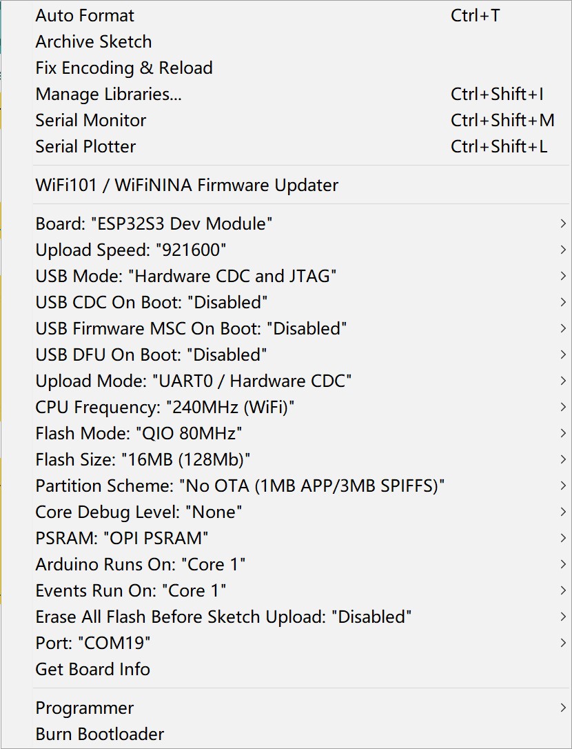
Note: Different PC has different Serial COM number
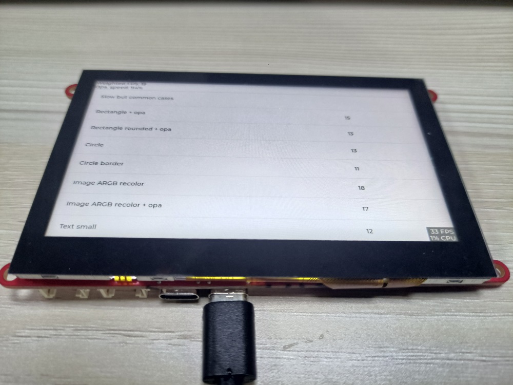
LvglBenchmark demo
This demo can test the fresh rate of the screen, in the 800*480 resolution ratio, it also has a good manifestation to display.
- Get the code in the GitHub, and open the example>>LvglBenchmark to download.
- Before users verify and upload the sketch, please installed the My_Lvgl library in the Arduino IDE.
1.Download the MF_Lvgl library.
2.Open the sketch>include library> ADD.ZIP library
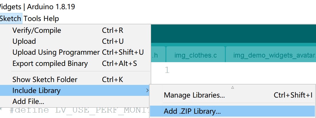
3.Choose the download path of MF_Lvgl and unzip the library.
4.Verify and upload the sketch.

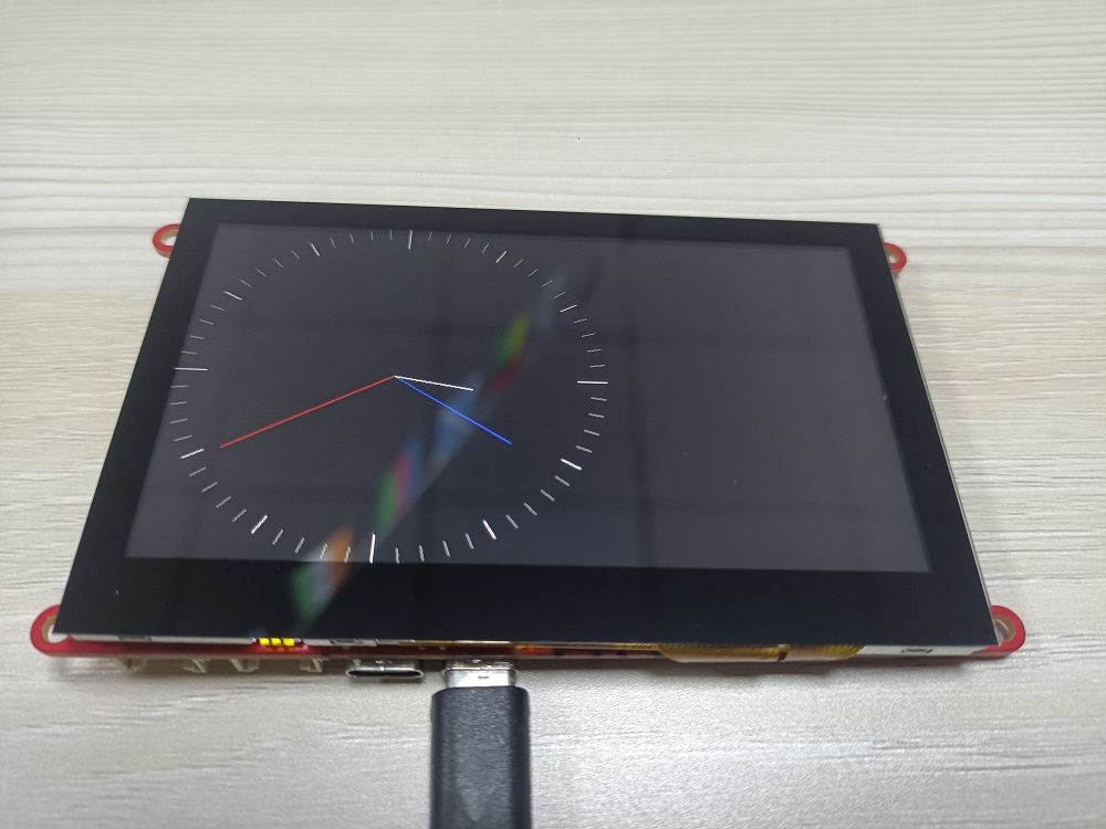
Clock demo
-
in our ESP32-S3-Parallel-TFT-with-Touch-4.3 inch, We increase the RTC(Real time clock), So it can record the time in time.
-
Get the code in the GitHub
-
Open the >> example>>clock, verify and upload the sketch.
PDQgraphicstest
-
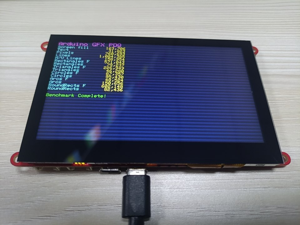
About this demo, which is a general graph test for the screen display.
-
Open the >> example>>PDQgraphicstest, and download the program.
-
Verify and upload the sketch.
-
Show the demo as follows.
Screen display demo
-
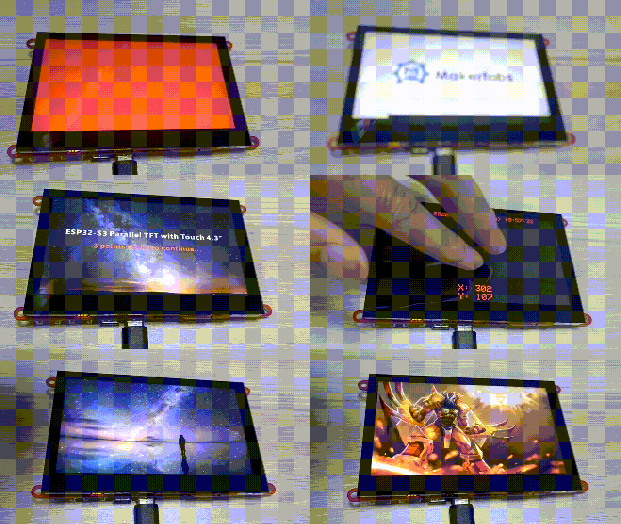
This board is 5 Points Touch, Capacitive. Its resolution ratio has 800*480, the display is excellent!
-
Open the >> firmware/esp32s3_4.3_tft_fw_test, and download the program.
-
Open the >>images, to download all the images to the SD card.
-
Verify and upload the sketch.
-
Show the demo as follows.
FAQ
You can list your question here or contact techsupport@makerfabs.com for technology support. Detailed descriptions of your question will be helped to solve your question.
Q1: Why the display fails to respond sometimes I touch?
- A1: The touching interface is loose, please reconnect it.
Q2: I get the error "no matching function for call to 'Arduino_ESP32RGBPanel::Arduino_ESP32RGBPanel(int, int, int, int, int, int, int, int, int, int, int, int, int, int, int, int, int, int, int, int, int, int, int)'); ^" when I compile the code, how to solve it?

- A2: Mabe you use the newest ArduinoGFX v1.4.7 not the tested v1.3.1. The oringinal code need to make some changes to support v1.4.7 as below:
#if 0  //for Arduino_GFX_Library v1.3.1
Arduino_ESP32RGBPanel *bus = new Arduino_ESP32RGBPanel(
    GFX_NOT_DEFINED /* CS */, GFX_NOT_DEFINED /* SCK */, GFX_NOT_DEFINED /* SDA */,
    40 /* DE */, 41 /* VSYNC */, 39 /* HSYNC */, 42 /* PCLK */,
    45 /* R0 */, 48 /* R1 */, 47 /* R2 */, 21 /* R3 */, 14 /* R4 */,
    5 /* G0 */, 6 /* G1 */, 7 /* G2 */, 15 /* G3 */, 16 /* G4 */, 4 /* G5 */,
    8 /* B0 */, 3 /* B1 */, 46 /* B2 */, 9 /* B3 */, 1 /* B4 */
);

// Uncomment for ST7262 IPS LCD 800x480
 Arduino_RPi_DPI_RGBPanel *gfx = new Arduino_RPi_DPI_RGBPanel(
   bus,
   800 /* width */, 0 /* hsync_polarity */, 8 /* hsync_front_porch */, 4 /* hsync_pulse_width */, 8 /* hsync_back_porch */,
   480 /* height */, 0 /* vsync_polarity */, 8 /* vsync_front_porch */, 4 /* vsync_pulse_width */, 8 /* vsync_back_porch */,
   1 /* pclk_active_neg */, 16000000 /* prefer_speed */, true /* auto_flush */);
#endif  //end of  for Arduino_GFX_Library v1.3.1

#if 1 //for Arduino_GFX_Library v1.4.7
Arduino_ESP32RGBPanel *rgbpanel = new Arduino_ESP32RGBPanel(
     40 /* DE */, 41 /* VSYNC */, 39 /* HSYNC */, 42 /* PCLK */,
     45 /* R0 */, 48 /* R1 */, 47 /* R2 */, 21 /* R3 */, 14 /* R4 */,
     5 /* G0 */, 6 /* G1 */, 7 /* G2 */, 15 /* G3 */, 16 /* G4 */, 4 /* G5 */,
     8 /* B0 */, 3 /* B1 */, 46 /* B2 */, 9 /* B3 */, 1 /* B4 */,
     0 /* hsync_polarity */, 8 /* hsync_front_porch */, 4 /* hsync_pulse_width */, 8 /* hsync_back_porch */,
     0 /* vsync_polarity */, 8 /* vsync_front_porch */, 4 /* vsync_pulse_width */, 8 /* vsync_back_porch */,
     1 /* pclk_active_neg */, 16000000 /* prefer_speed */);
 Arduino_RGB_Display *gfx = new Arduino_RGB_Display(
     800 /* width */, 480 /* height */, rgbpanel, 0 /* rotation */, true /* auto_flush */);
#endif   //End of for Arduino_GFX_Library v1.4.7
Note: If the users can't upload code due to unknown reason. people can try to download the bin.zip**
1.Download the flash download tool - https://www.espressif.com/sites/default/files/tools/flash_download_tool_3.9.4_0.zip
2.Select ESP32S3
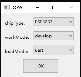
3.input the address with the related file.
0x0       xxx.ino.bootloader.bin
0x8000    xxx.ino.partitions.bin
0xe000    boot_app0.bin
0x10000   xxx.ino.bin
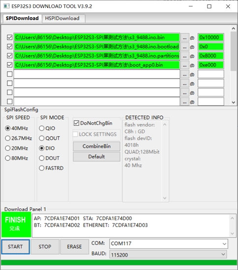
4.Reset the board after the download is finished.
Notice there need a 480X320 logo.bmp in microSD card.