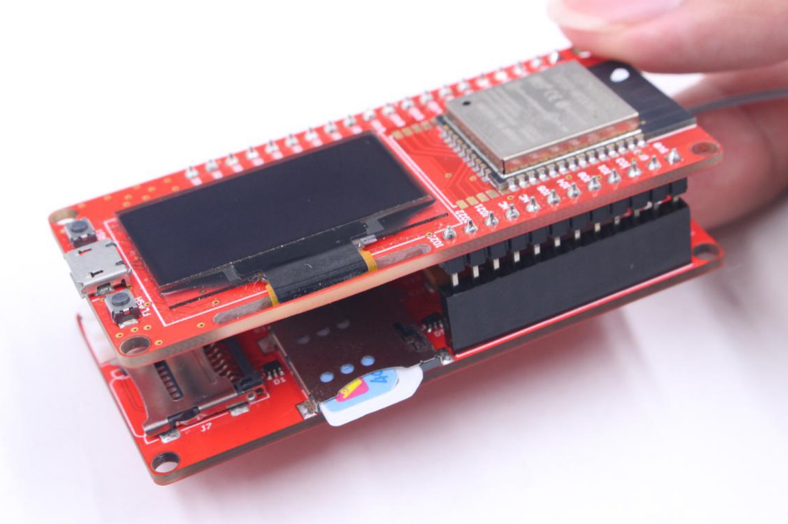
MaESP A9G
Introduction
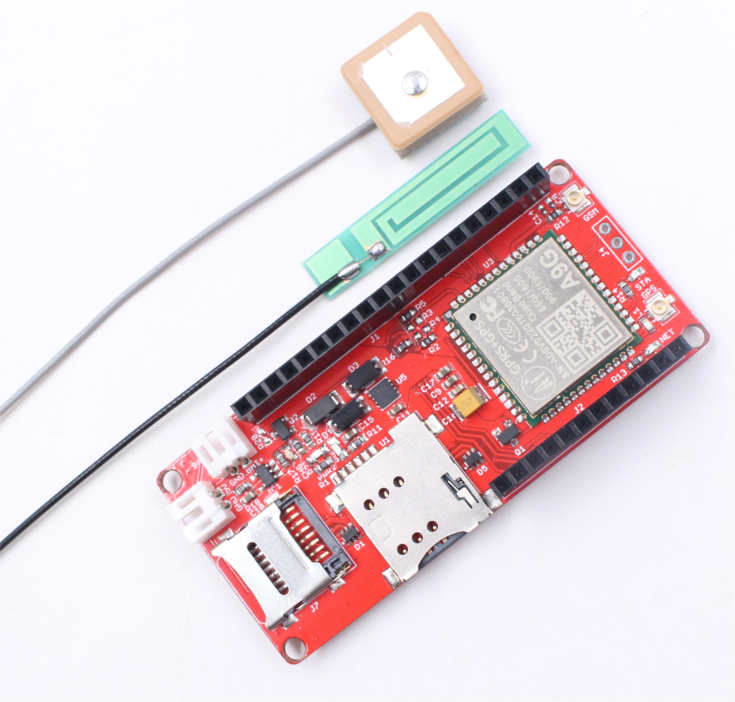
MaESP A9G is an IOT for GPRS / GSM + GPS module, users can use Thonny/Arduino to program it, which is very easy, especially for non-programmers. There is also a user guide to learn how to use the board to create the first IOT project, which allows beginners to quickly learn hardware and programming skills.
With this board, you will easy to add text, SMS and data to your project. It is good for your smart home project or GPS tracker and so on.
Model:OAC010A9G
Features
- Micro SIM connector
- Support AT Command
- Quad-band: 850/900/1800/1900Mz
- Support GPS
- Support GPRS data traffic, the maximum data rate, download 8- - 5.6Kbps, upload 42.8Kbps
- Support SMS text messaging
- Support Micro SD Card
- Working Temperature: -40 – 85℃
- Size: 70*32.6mm
Usage
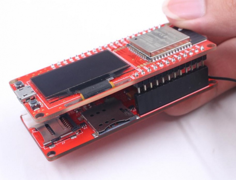
This MaESP A9G can do nothing. It needs a microcontroller like ESP32 to drive it. The following routines are implemented by A9G with MaESP ESP32 OLED, they can be directly combined to achieve various functions.
Warning: Don’t operate anything when the board supplied on (That is, plug or unplug the Antenna or Sensor, in case of short-circuiting that may burn the IC down.)
MaESP A9G OLED Projects in Thonny
Note: MaESP ESP32 OLED can be developed using micropython, provided the corresponding firmware is required. You can download the micropython firmware for esp32 from the official website and burn it.
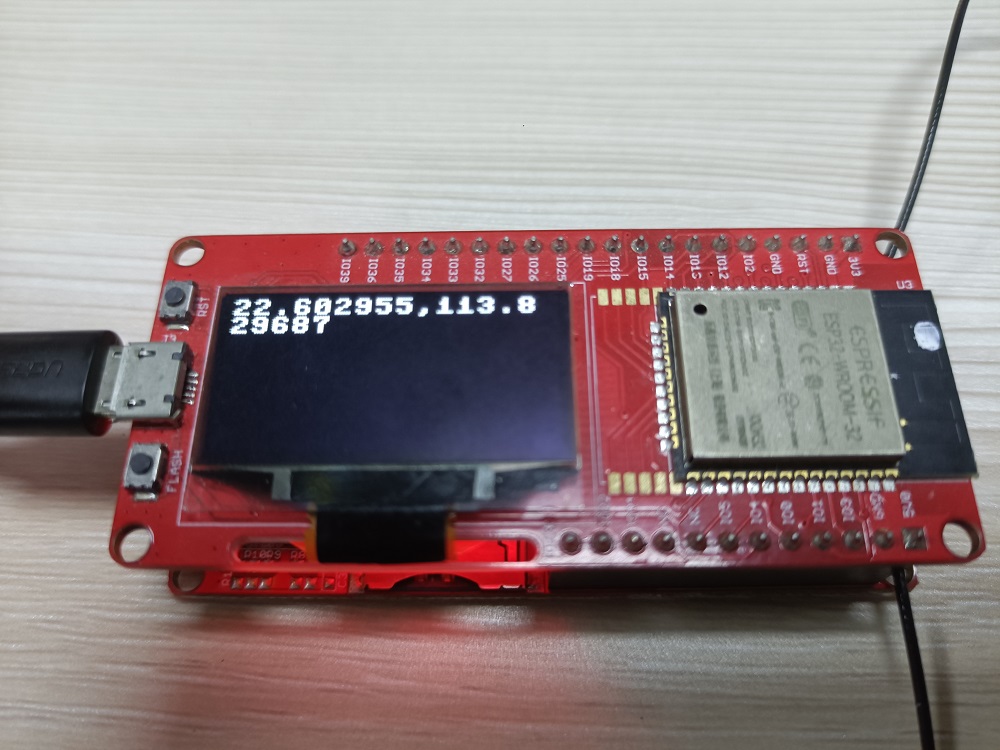
Project_1: Shows the GPS location on OLED display
Attention: To get GPS location, please ensure you are outdoors, and plug the GPS Antenna. Indoor may get the incorrect location or no location information.
Step:
1.Plug in the GPS antenna
2.Plug to MaESP ESP32, and connect the USB to the PC.
3.Sample code, or you can get it from here:A9G_GPS.py
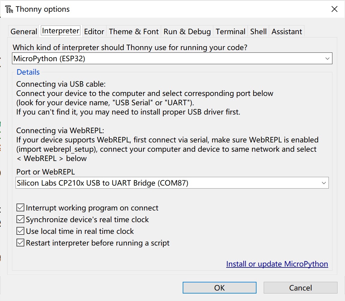
4.Open the Thonny, click Tools > Option>>interperter
Choose the interpreter and port:
- Go to View> Files
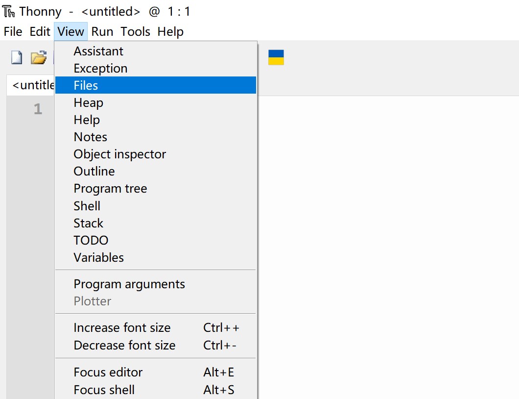
- Go to the path where you downloaded the file, and upload the code in Thonny.
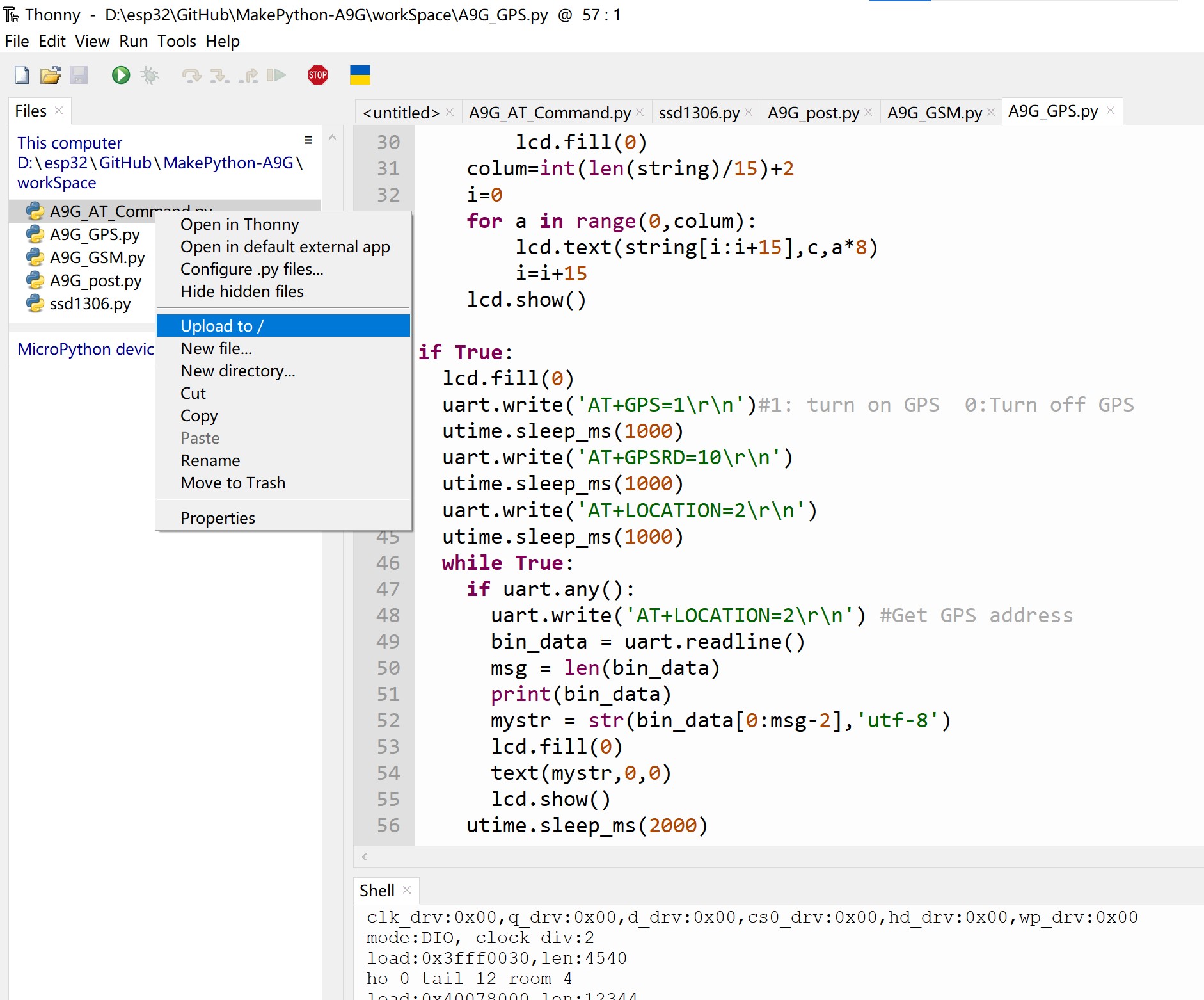
- Click the A9G_GPS.py, and Press the Connect button to establish serial communication with your board.

- The screen displays NEMA message.
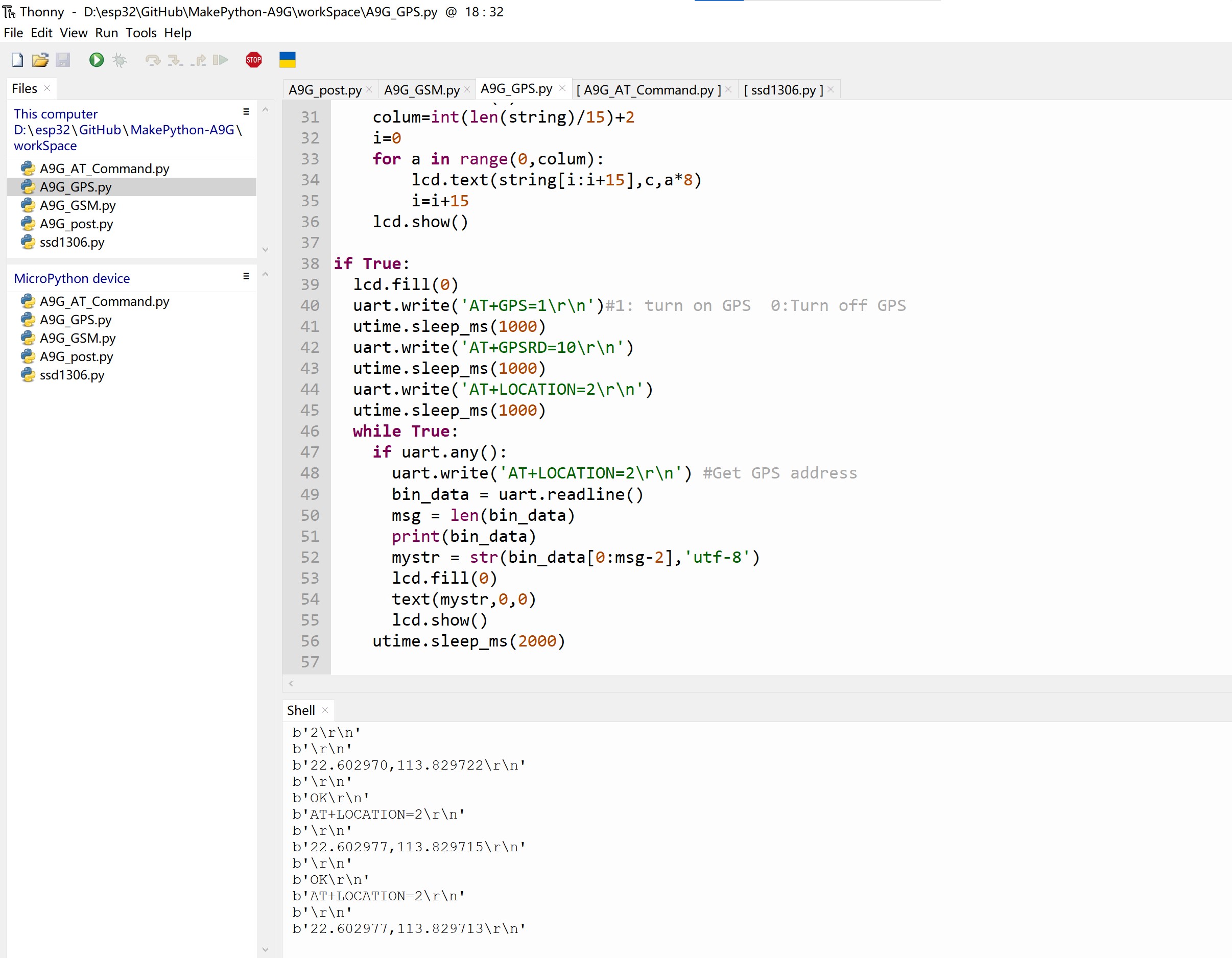
-
Location information may not be received indoors, and GPS NOT FIX NOW will be displayed on the screen if reception fails.
-
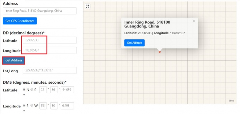
We can show our location where we are in https://www.gps-coordinates.net/.
Project_2: Display SMS message on OLED display
Please note that each text message may require some fees depending on your local GSM operator, make sure the SIM card is active, and leave enough money for this application.
This example also uses MakePython ESP32 for MicroPython programming. Step:
1.Plug in the GSM antenna
2.Insert a mini SIM card(GPS does work without a SIM)
3.Open the A9G_GSM.py, and Click the run currect script button

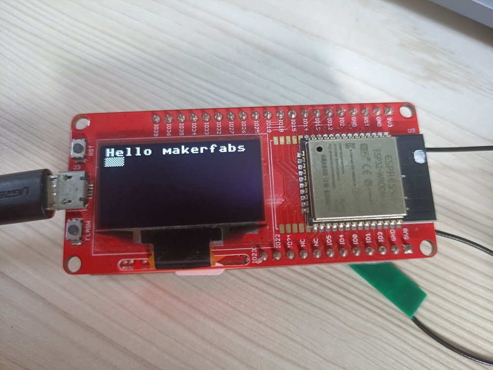
4.The screen displays the phone number, time and information for sending SMS.
- Mobile phone to send SMS.

- Display the phone number and time of sending SMS
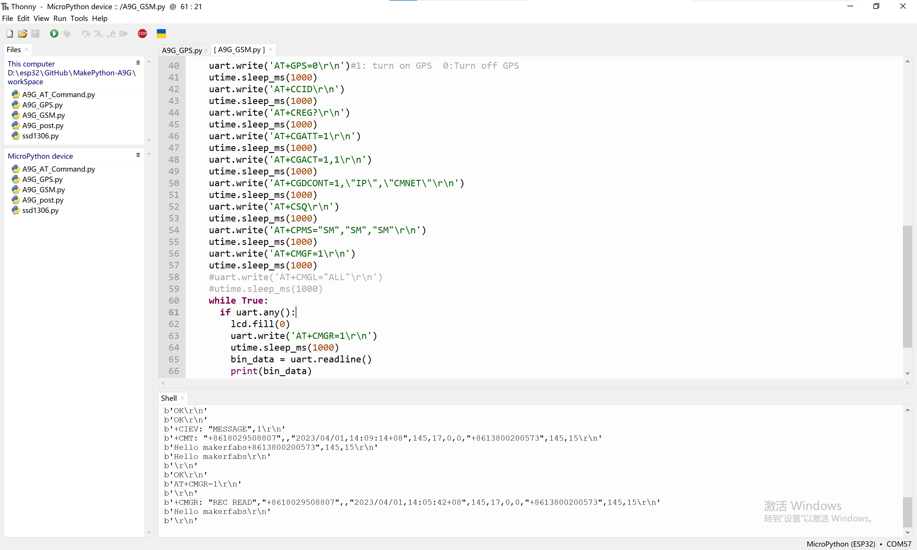
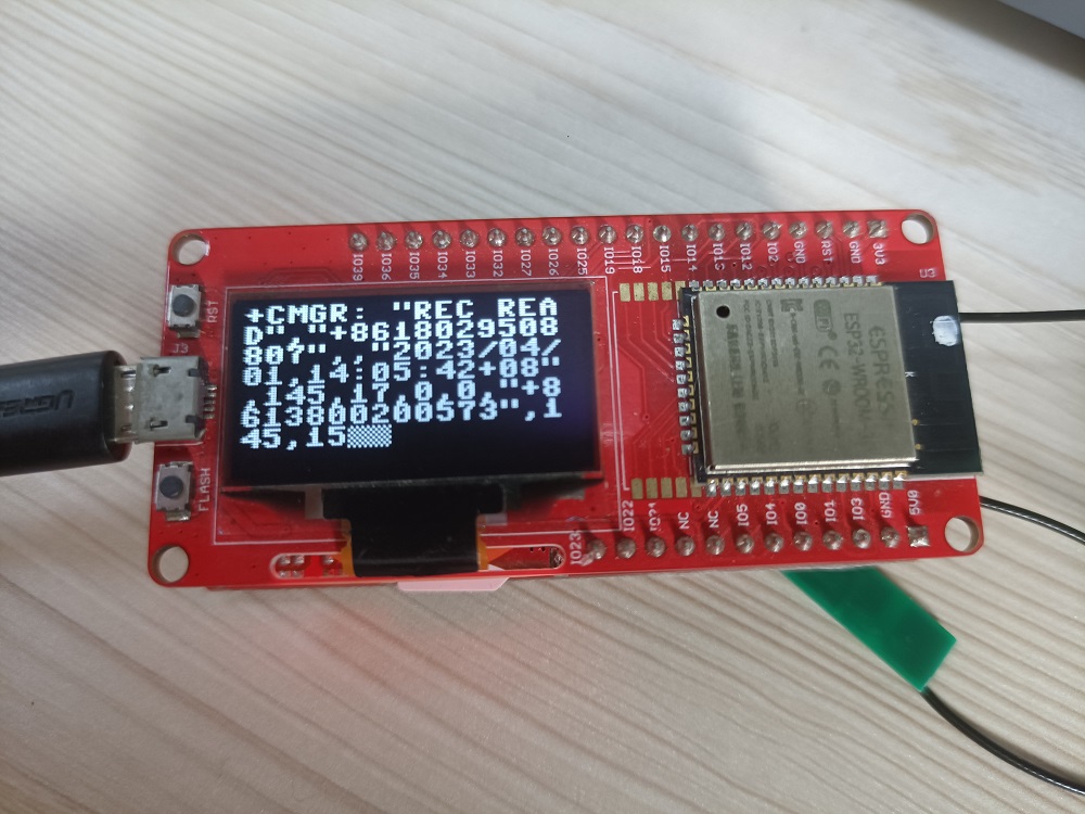
- Show received content
MaESP A9G OLED Projects in Arduino
Note:Running the MaESP ESP32 OLED with Arduino requires the corresponding firmware
AT command test Demo
With the Arduino, you can test the AT Command to realize the A9G function as follows.
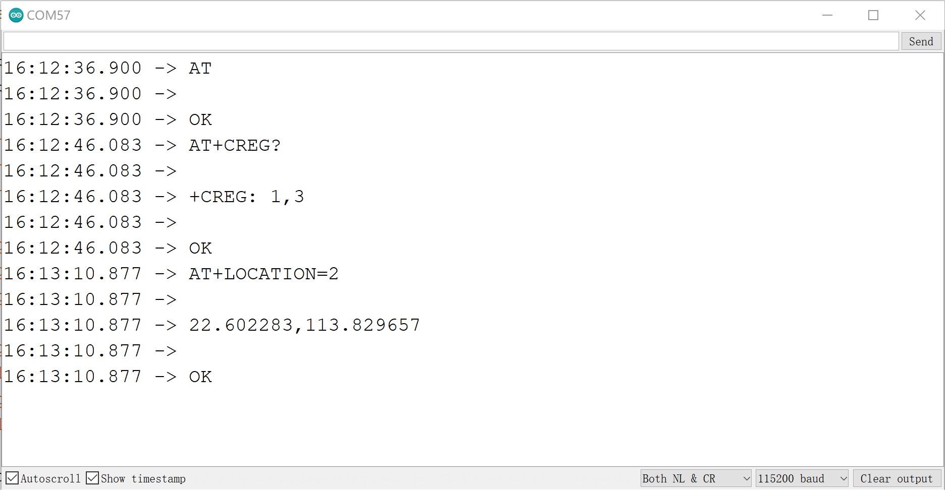
AT+GPS=1   #1:Turn the GPS on, 0:Turn the GPS off
AT+CCID    #Query SIM, unique serial number, can be used to judge whether the card is normal
AT+CREG?   #Check the registration status of the network
AT+CSQ     #Query signal strength, the first parameter is the signal strength value
AT+CGATT=1  #Attach to the network, if you need to access the Internet, this command is mandatory
AT+CGDCONT=1,”IP”,”CMNET”   #Set PDP parameters
AT+CGACT=1,1      #Activate PDP, you can go online after activation
AT+GPSRD=N    #N is a number indicating that a NEMA message is read every N seconds
AT+GPSRD=0    #Stop reporting
AT+LOCATION=2   #Get the address information of GPS, as long as the GPS can see the satellite before returning, otherwise, it will return GPS NOT FIX NOW
AT+CPMS="SM","SM","SM"   #Set up SMS storage unit
AT+CMGF=0/1      #Set the SMS format, 1 for text format reading, 0 for pud format reading
AT+CMGR=x        #Read SMS content, x is the number of SMS
AT+CMGL=4/"ALL"   #View the SMS list. The reading parameter in PUD format is 4, and the reading parameter in txt format is "ALL"
AT+CMGD=1       #Delete the text message. If you use AT + CMGD = 1,4 then delete all SMS
-
Open the GitHub, click >> arduino_example>>at_command.ino and download it.
-
Select and set the parameter in the Tools menu, as the picture:
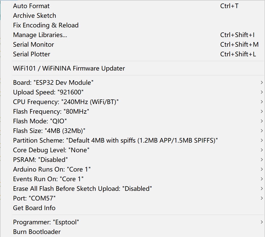

- After verifying and unloading the code, you can test the AT command in the serial monitor
FAQ
You can list your question here or contact techsupport@makerfabs.com for technology support. Detailed descriptions of your question will be helped to solve your question.