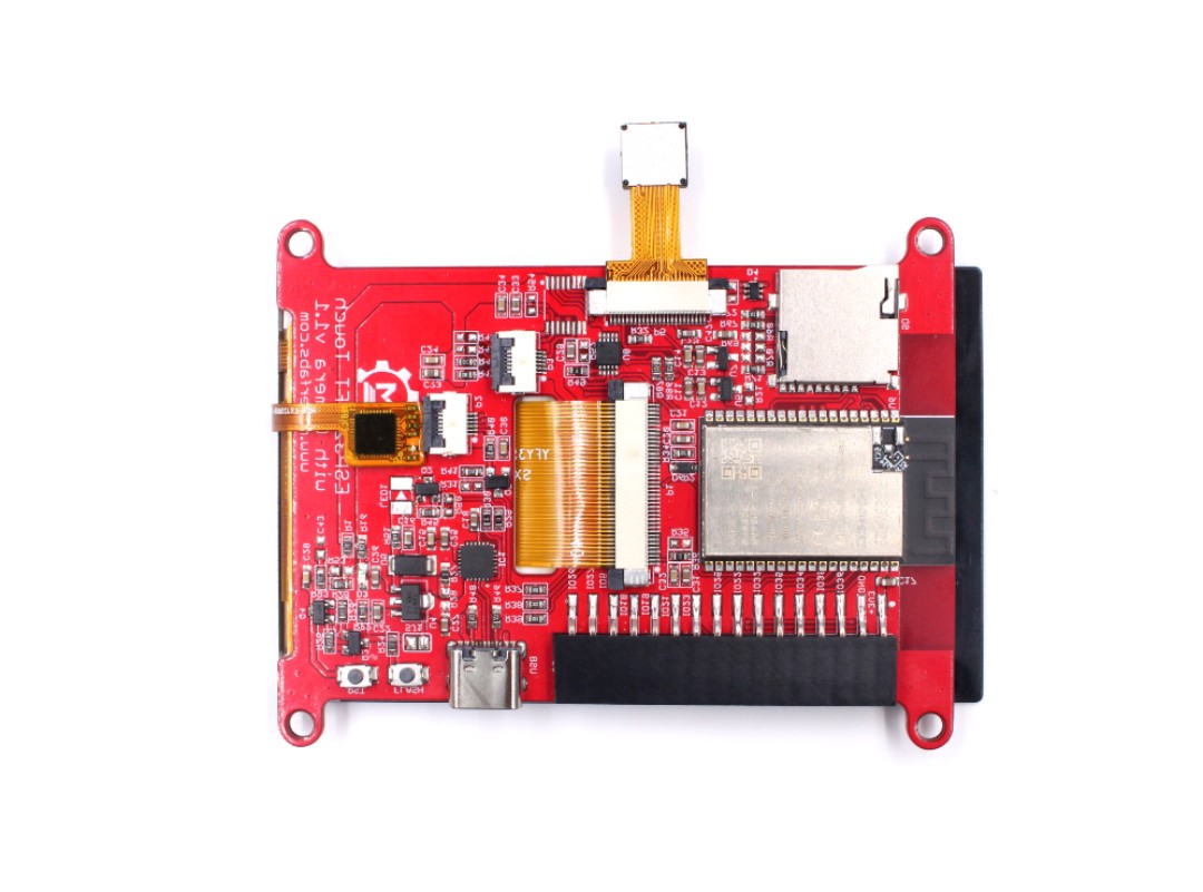
ESP32 3.5" TFT Touch with Camera
Introduction
The 3.5" 320x480 TFT LCD driver is ILI9488, it uses SPI for communication with ESP32, the SPI main clock could be up to 60M~80M, make the display smooth enough for videos; and the camera OV2640 with pixel 2M, with this camera, you can make applications such as remote photography, face recognition…. While the camera is not used, you can freely use all these pins with the breakout connectors, to connect the ESP32 display with sensors/ actuators, suitable for IoT applications.
Model: Resistive: ESPTFT35RE
Model: Capacitive: ESPTFT35CA
Features
- Integrated ESP32 Wrover 2.4G WiFi and Bluetooth
- Wi-Fi Protocols: 802.11b/g/n(802.11n up to 150Mbps),A-MPDU and A-MSDU aggregation and 0.4us guard interval support
- Wi-Fi Frequency range: 2.402GHz - 2.483Ghz
- Bluetooth Protocols: Bluetooth v4.2 BR/EDR and BLE specification
- Bluetooth Radio: NZIF receiver with-97 dBm sensitivity, Class-1/class-2 and class-3 transmitter, AFH
- Bluetooth Audio: CVSD and SBC
- Arduino Compatible: You can play it with Arduino IDE
- OV2640: A 1/4inch CMOS UXGA (1632*1232) image sensor manufactured by OmniVision
- OV2640 supports output images up to 2 million pixels
- LCD 3.5 inch Amorphous-TFT-LCD (Thin Film Transistor Liquid Crystal Display) for mobile-phone or handy electrical equipment
- LCD Driver: ILI9488
- LCD Resolution: 320*480
- NS2009: A 4-wire resistive touch screen control circuit with I2C interface, which contains A 12-bit resolution A/D converter
- FT6236 Series ICs are single-chip capacitive touch panel controller IC with a built-in 16 bit - enhanced Micro-controller unit (MCU)
- Power supply: 5V, Type-C USB
- Micro SD card slot on the board
- Board size: 66mm * 85mm
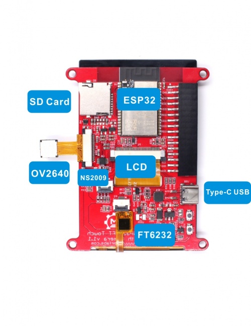
Diagram
Pin Assignment
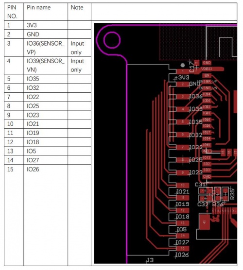
Note:IO34/IO35/IO36/IO39 input only.
Dimension
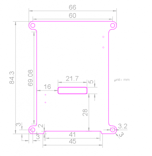
Note:unit is mm.
Usage
Warning: Don't operate when in power supply on
Github:Project_Touch_Screen_Camera
Software setup
NOTE: In order for the project to work normally, please install the same version.
1.Install the Arduino IDE V1.8.10.
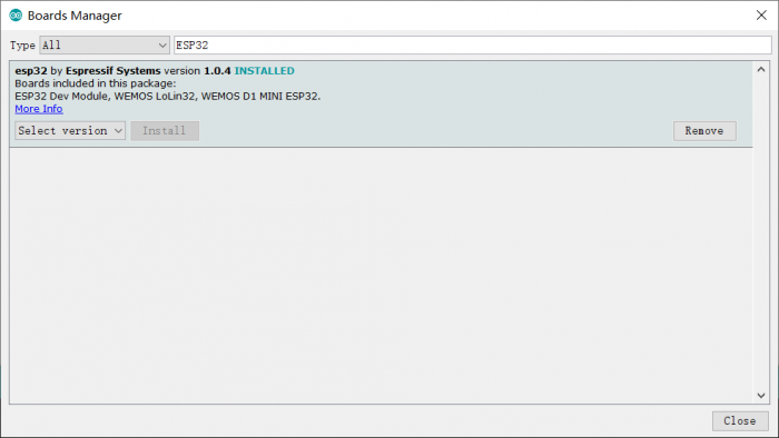
2.Install the ESP32 boards supporting V1.0.4
-
After Arduino IDE installed, there is no package to support ESP32, we need to install the ESP32 package in Arduino IDE to continue.
-
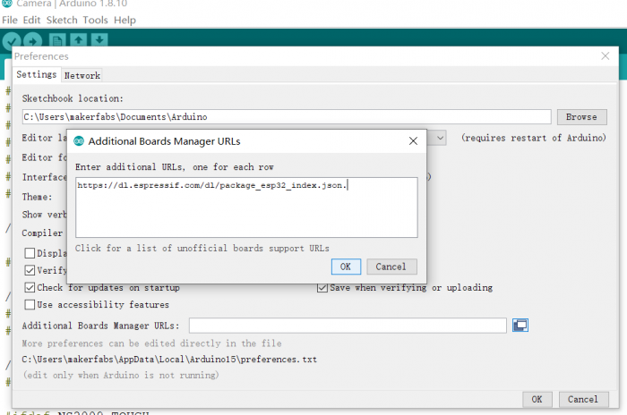
Select “File>Preferences>settings>Additional Boards Manager URLs” to fill the link: https://dl.espressif.com/dl/package_esp32_index.json
- Click “Tools>Board>Boards Manager” to search for and install the ESP32 library:
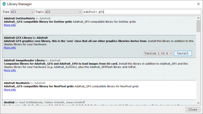
3.Install Adafruit GFX library V1.10.4
- Click “Tools> Manager Libraries” to search for and install Adafruit GFX library.
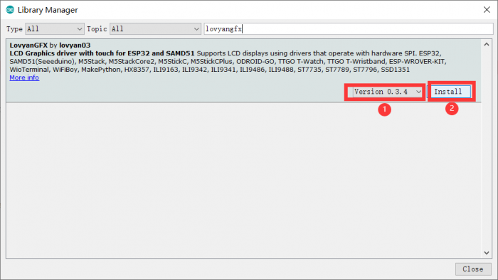
4.Install LovyanGFX library V0.3.4
- Click “Tools> Manager Libraries” to search for and install LovyanGFX library.
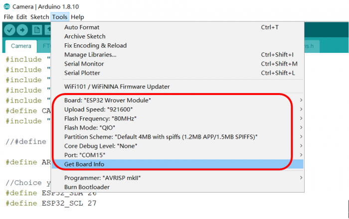
5.Select and setting the parameter in the Tools menu, as the picture:
Draw on LCD
-
You can get the code from here: Core
-
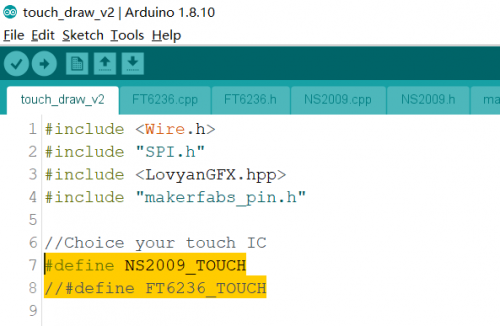
Open the file “\Project_Touch-Screen-Camera-master\touch_draw_v2\touch_draw_v2.ino”. Select the screen type used and comment out the ones that are not used.
#include <Wire.h>
#include "SPI.h"
#include <LovyanGFX.hpp>
#include "makerfabs_pin.h"

//Choice your touch IC
#define NS2009_TOUCH    //Resistive screen driver
//#define FT6236_TOUCH  //Capacitive screen driver
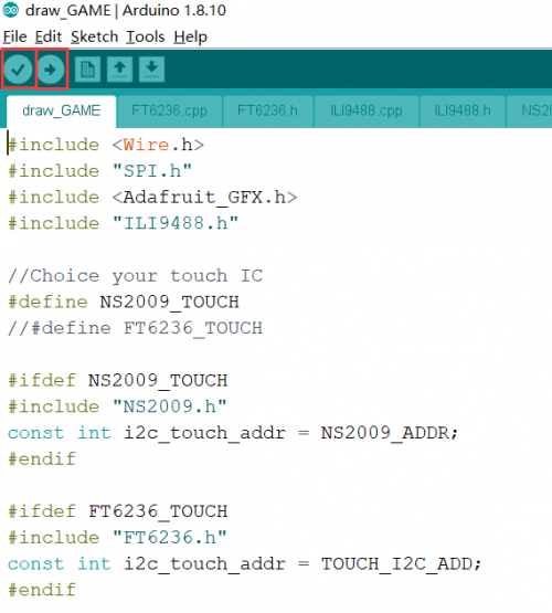
- Verify it and upload.
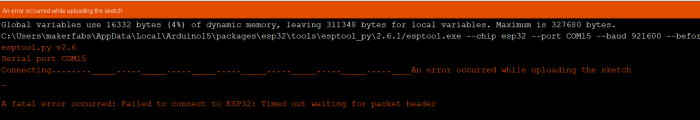
If failed to upload the code as the picture, please upload again and try to press the Flash switch when the code is uploading.
- After done uploading, repower the ESP32 and you will get the drawing board.
Display the picture
-
You can get the code from here:Core
-
Copy the picture you want to show to the SD card. Insert the SD card into the board.
-
Open the file “\Project_Touch-Screen-Camera-master\SD2TFT\SD2TFT.ino”. The name of the showed picture must be filled in the string array, such as the below code.
String img_file[5] =
    {
        "/1.bmp",
        "/2.bmp",
        "/3.bmp",
        "/4.bmp",
        "/5.bmp"};
- Verify and upload the code, you will get a digital photo frame.
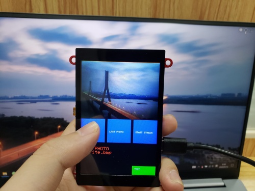
Camera
-
You can get the code from here: Core
-
Open the file “\Project_Touch-Screen-Camera-master\Camera_v2\Camera_v2.ino”. Choose the screen type and modify the code.
//#define NS2009_TOUCH  //Resistive screen driver
#define FT6236_TOUCH //Capacitive screen driver

#ifdef NS2009_TOUCH
#include "NS2009.h"
const int i2c_touch_addr = NS2009_ADDR;
#define get_pos ns2009_pos
#endif

#ifdef FT6236_TOUCH
#include "FT6236.h"
const int i2c_touch_addr = TOUCH_I2C_ADD;
#define get_pos ft6236_pos
#endif
- Verify and upload the code, you will get a camera.
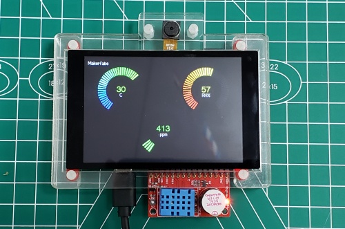
Indoor Environment Expansion board
This is an expansion board for measuring CO2, TVOC, Temperature, and Humidity. The board is design for ESP32 TFT LCD with Camera(3.5')(also for 3.2' one). For using, plug the board into the ESP32 TFT LCD board directly, program the ESP32. The ESP32 TFT LCD will turn to a meter for monitoring the environment.
Model: Indoor Environment Expansion
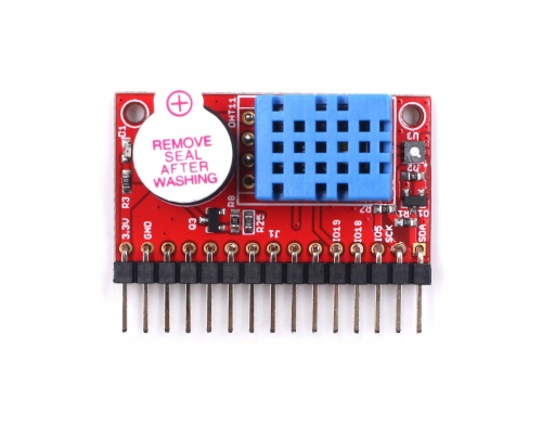
Features
- SGP30 Air Quality Sensor, measuring TVOC and CO2.
- DHT11 temperature and humidity sensor.
- Active buzzer.
Hardware
- Schematic
Using
- Plug the expansion board into the ESP32 TFT LCD board.
- Loading the program obtained from GitHub.
- Reset the ESP32, and wait a minute.
- The LCD will display the measure of CO2, Temperature, Humidity.
- When the CO2 level is high over 1000, the buzzer on board rings.
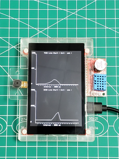
Display CO2 historical level
- Plug the expansion board into the ESP32 TFT LCD board.
- Loading the program.
- Reset the ESP32 board, the ESP32 will start to record the CO2 level and TVOC level, and draw the historical values to line.
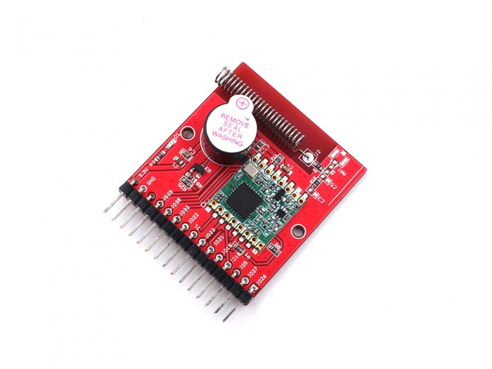
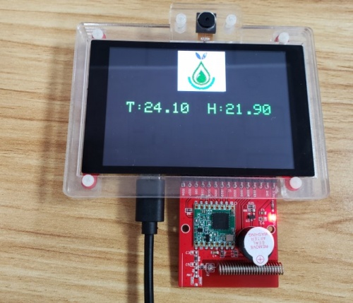
Use with LoRa Radio Expansion
LoRa Radio expansion based on the LoRa module and provided a wireless Lot solution (ESP32-LoRa). This board is designed for ESP32 3.5" TFT Touch with Camera (also for the 3.2" one), mainly used with the ESP32 3.5" TFT Touch board.
Model:LoRa Radio Expansion
- Onboard LoRa module (433Mhz, 868Mhz or 915Mhz)
- Long-distance communication: 2km or more
- Active buzzer
- Power by 3.3V
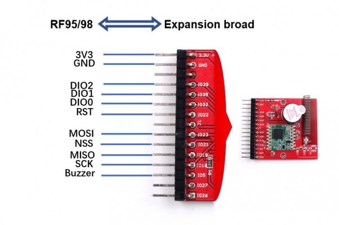
interface
Using Demo
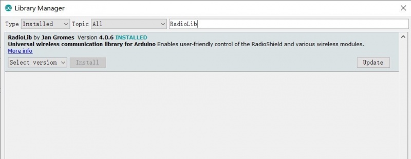
1.Open the code by Arduino IDE, it is required to install the library (RadioLib.h) for the LoRa module to work.
2.According to the schematic, it has to configure the pin connection in the code.
#define LORA_MOSI 23
#define LORA_MISO 19
#define LORA_SCK 18
#define LORA_CS 21

#define LORA_RST 22
#define LORA_DIO0 32
#define LORA_DIO1 35
3.The default frequency setting is 433Mhz in the code, if you want other frequency LoRa modules (such as 868Mhz or 915Mhz) working, it needs to make two changes in the code.
#define FREQUENCY 434.0     //868.0 or 915.0
#define BANDWIDTH 125.0
#define SPREADING_FACTOR 9
#define CODING_RATE 7
#define OUTPUT_POWER 10
#define PREAMBLE_LEN 8
#define GAIN 0
SPIClass SPI_Lora = SPIClass(HSPI);
//SX1278 radio = new Module(LORA_CS, LORA_DIO0, LORA_RST, LORA_DIO1, SPI_Lora, SPISettings());   //433Mhz
SX1276 radio = new Module(LORA_CS, LORA_DIO0, LORA_RST, LORA_DIO1, SPI_Lora, SPISettings());   // 868Mhz or 915Mhz
4.Verify the code and upload it to the ESP32 board. 5.The board will receive something by LoRa and display the receiving on the screen.
FAQ
You can list your question here or contact techsupport@makerfabs.com for technology support. Detailed descriptions of your question will be helped to solve your question.
- Q1: Why the display fails to respond sometimes I touch? A1: The touching interface is loose, please reconnect it.
- Q2: Can't upload the code. A2:Let ESP32 in download mode by pressing the RESET key after holding the FLASH key when you're uploading the code.